This chapter describes how to use a distance sensor to enable the robot to see and avoid
obstacles as it moves around. The first sketch, named myRobotWander, drives
the robot forward, and if it detects an obstacle, it stops and rotates the robot to try and
find a clear path to move forward. Another sketch, named myRobotScan, adds
a servo that can rotate the sensor so the robot can look left and right without having to
twist itself around.
Ping distance sensor from Parallax; see Sonar Distance Sensors in Chapter 8, Tutorial: Introduction to Sensors.
Servo required for myRobotScan; see Sonar Distance Sensors in Chapter 8, Tutorial: Introduction to Sensors.
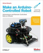
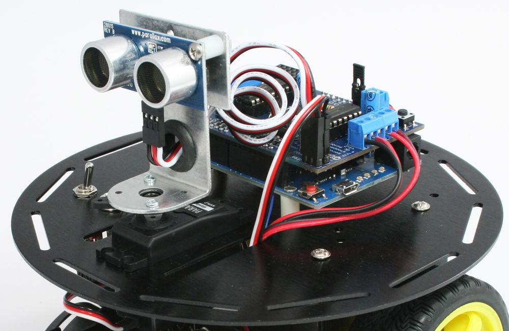
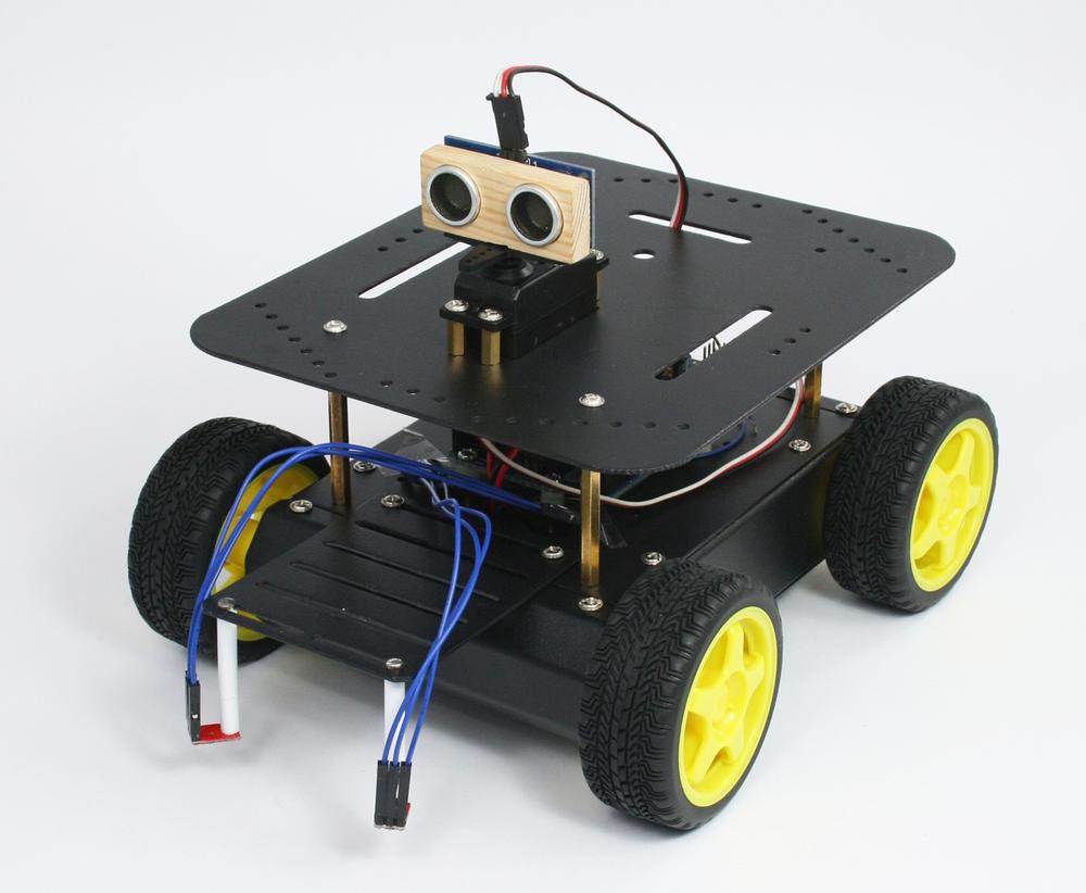
Connect the Ping sensor and servo the right way around; the black wires (ground) go nearest the pin marked -, the white (or lighter color) signal wire goes nearest the pin marked S (Figure 10-1).
myRobotWander.inoUses a SONAR distance sensor (the Ping sensor) to enable the robot to see and avoid obstacles as it wanders around.
#definesare added for front and rear obstacles (only the front is implemented in the sketch), the look module has added support for distance sensing. This sketch introduces a new tab, named Distance, which contains the Ping sensor code that you originally saw in Sonar Distance Sensors.myRobotScan.inoHas the sensor mounted on a servo so it can scan independently of robot movement. This code is similar to
myrobotWanderwith the Look module enhanced to support control of the servo to look around. A new module named softServo is added for servo control.
Note
The Distance tab's code is not listed in this chapter, but it is included in the example code (see How to Contact Us for information on downloading the example code).
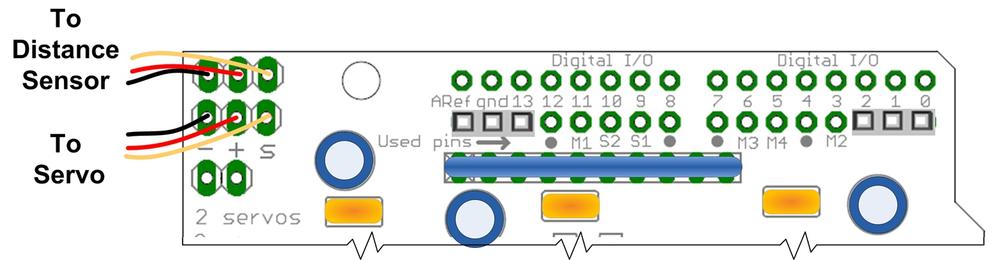
Figure 10-2 shows the modules used in this chapter.
There are various ways to mount a Ping sensor. You can buy a commercial off-the-shelf product such as the one illustrated in Figure 10-3.
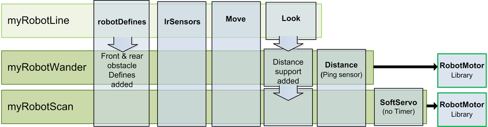
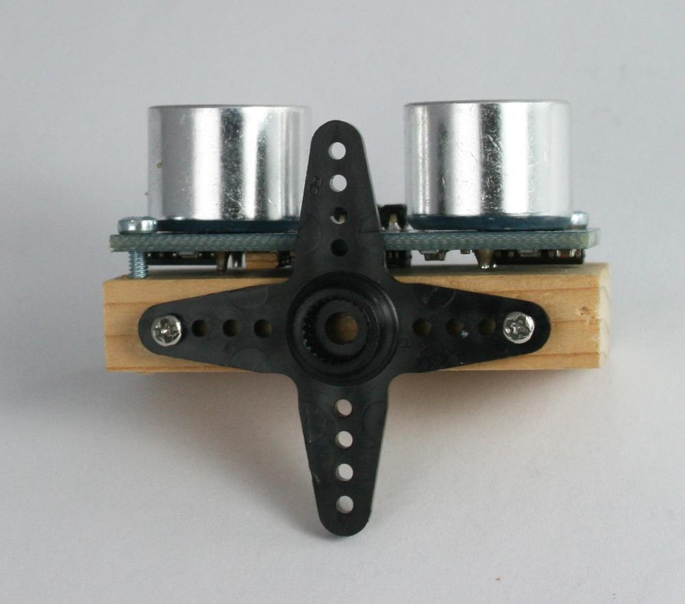
The bracket shown in Figure 10-4 and Figure 10-5 is another commercial off-the-shelf bracket that mounts the sensor on a servo so it can be rotated to scan for objects on either side of the robot. If you use a commercial off-the-shelf product, follow the supplied instructions for assembly and mounting.
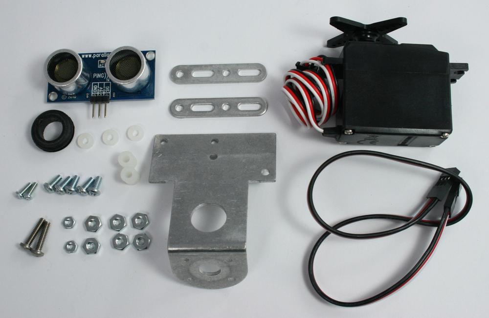
If you prefer to make a bracket, it's easy to do, as the next section explains.
You can make a simple mount from a small piece of wood. A small mount can be cut from 1" x 1 3/4" x 3/8" pine. You can drill holes for bolts (4-40 or M3) or use small wood screws to attach the sensor. The holes are close to the edges, so drill pilot holes if you use wood screws. Figure 10-6 shows a template you can use for the mount. You can see the Ping sensor attached to the mount in Figure 10-7 and Figure 10-8.
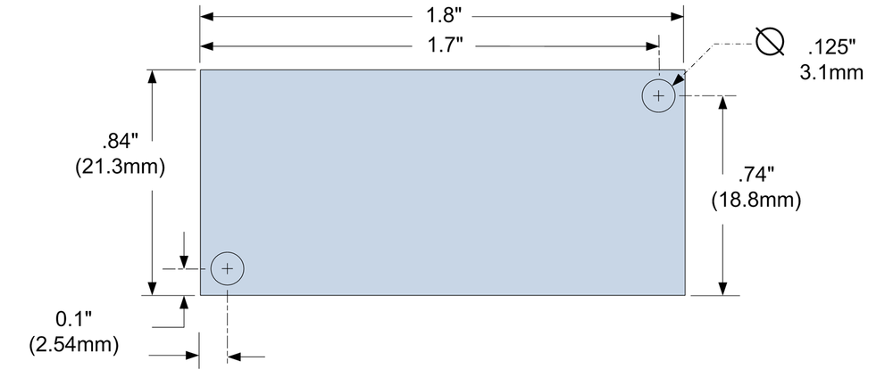
Figure 10-7 shows the a small block of wood cut and drilled.
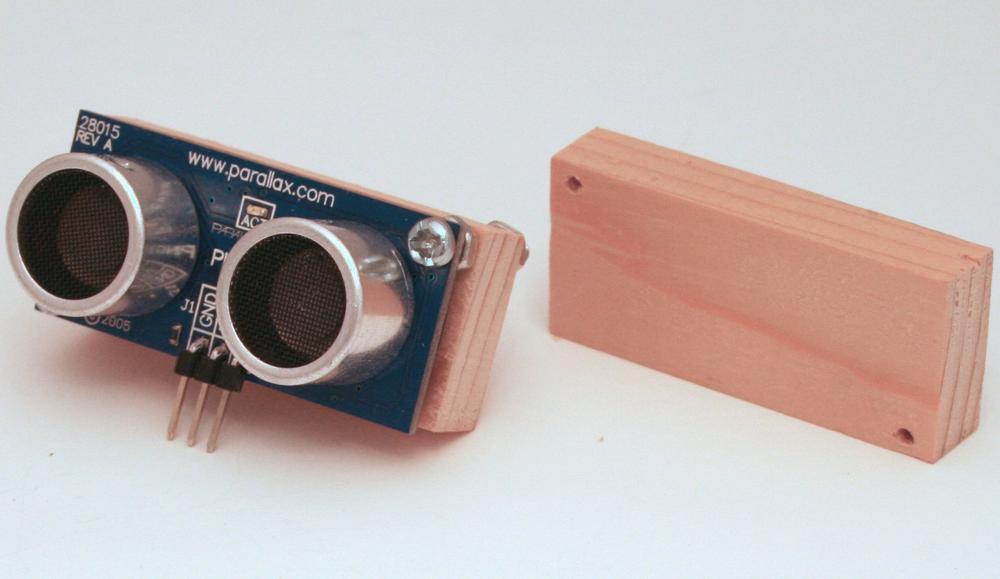
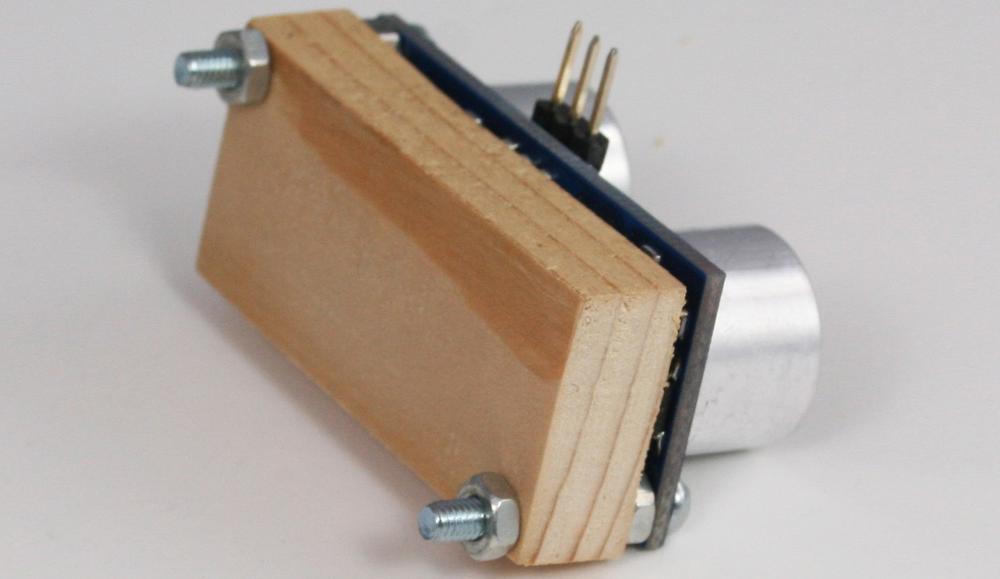
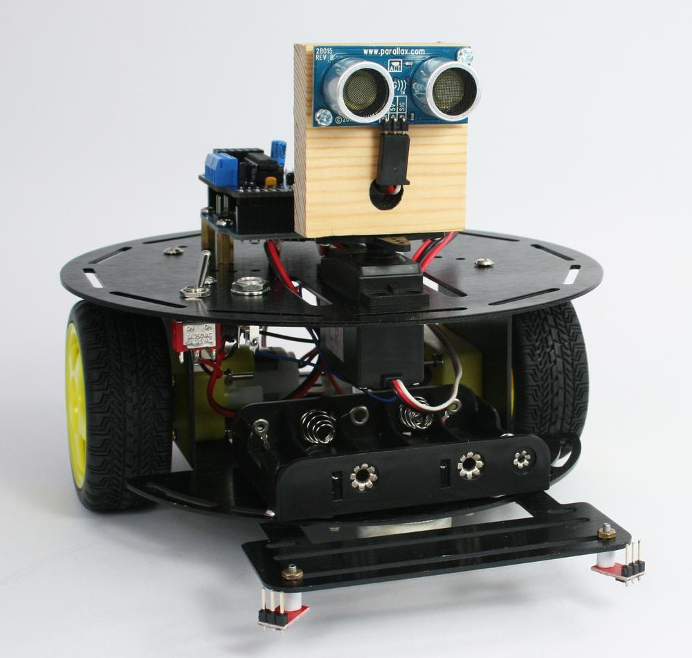
Figure 10-9 and Figure 10-10 show the mount attached to the robot.
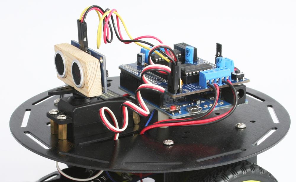
The manufactured mounts are supplied with mounting hardware. If you are using a homemade wooden mount, you can attach it to the base with two wood screws from the underside of the top plate.
The wooden mounts can be hot glued or screwed onto the servo horn supplied with the servo as shown in Figure 10-11. Figure 10-11 showed the sensor attached to a servo that's attached to the 2WD. Figure 10-12 shows the sensor on a servo attached to the 4WD.
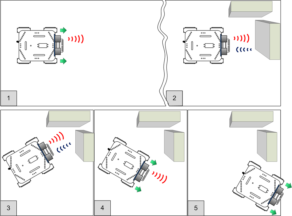
The myRobotWander sketch adds support for a fixed forward-facing
distance sensor that enables the robot to move forward when no obstacle is detected (panel 1 in Figure 10-13).
The robot stops when approaching an obstacle ahead (panel 2). It rotates left (panel 3) to see
if there is an obstacle in that direction. If no obstacle is seen, the robot will turn in that
direction and move off. If the left is obstructed, it will turn right and move off in that
direction (panel 5). If both left and right are blocked, the robot will turn around and move
off in the opposite direction.
The code to provide this behaviour is in the sketch named
myrobotWander. Example 10-1 shows the main myRobotWander tab for this sketch.
Example 10-1. Contents of the sketch's main tab
/******************************************************************************
myRobotWander.ino

Robot wanders using forward scanning for obstacle avoidance

Michael Margolis 28 May 2012
******************************************************************************/

#include <AFMotor.h>  // adafruit motor shield library
#include "RobotMotor.h"    // 2wd or 4wd motor library

#include "robotDefines.h"  // global defines

// Setup runs at startup and is used configure pins and init system variables
void setup()
{
  Serial.begin(9600);
  blinkNumber(8); // open port while flashing. Needed for Leonardo only

  lookBegin();
  moveBegin();
  moveSetSpeed(MIN_SPEED + 10) ;  // Run at 10% above minimum speed
  Serial.println("Ready");
}

void loop()
{
   moveForward();
   roam();  // look around
}

// function to indicate numbers by flashing the built-in LED
void blinkNumber( byte number) {
   pinMode(LED_PIN, OUTPUT); // enable the LED pin for output
   while(number--) {
     digitalWrite(LED_PIN, HIGH); delay(100);
     digitalWrite(LED_PIN, LOW);  delay(400);
   }
}
This simply initializes the 'Look' module (The Look Code) and 'Move' module
(Core Movement Code) and then calls a function named roam that
does all the hard work of looking for obstacles and moving to avoid them. The
roam function is added into code in the Look tab; Example 10-2 replaces the entirety of the Look tab code that you saw in earlier examples.
Example 10-2. The new version of the Look tab code
/**********************
 code to look for obstacles
**********************/

const int  MIN_DISTANCE = 8;     // robot stops when object is nearer (in inches)
const int  CLEAR_DISTANCE = 24;  // distance in inches considered attractive to move
const int  MAX_DISTANCE = 150;   // the maximum range of the distance sensor

// angles                 left, right, center
const int lookAngles[] = {  -30,  30,   0};

const byte pingPin = 10; // digital pin 10

void lookBegin()
{
  irSensorBegin();    // initialize sensors
}

// returns true if the given obstacle is detected
boolean lookForObstacle(int obstacle)
{
  switch(obstacle) {
     case  OBST_FRONT_EDGE: return irEdgeDetect(DIR_LEFT) && irEdgeDetect(DIR_RIGHT);
     case  OBST_LEFT_EDGE:  return irEdgeDetect(DIR_LEFT);
     case  OBST_RIGHT_EDGE: return irEdgeDetect(DIR_RIGHT);
     case  OBST_FRONT:     return  lookAt(lookAngles[DIR_CENTER]) <= MIN_DISTANCE;
  }
  return false;
}

// returns the distance of objects at the given angle
// this version rotates the robot
int lookAt(int angle)
{
  moveRotate(angle);   // rotate the robot

  int distance, samples;
  long cume;
  distance = samples = cume = 0;
  for(int i =0; i < 4; i++)
  {
    distance = pingGetDistance(pingPin);
    if(distance > 0)
    {
      //  printlnValue(" D= ",distance);
      samples++;
      cume+= distance;
    }
  }
  if(samples > 0)
    distance = cume / samples;
  else
    distance = 0;

  moveRotate(-angle);   // rotate back to original direction
  return distance;
}

// function to check if robot can continue moving in current direction
// returns true if robot is not blocked moving in current direction
// this version only tests for obstacles in front
boolean checkMovement()
{
  boolean isClear = true; // default return value if no obstacles
  if(moveGetState() == MOV_FORWARD)
  {
    if(lookForObstacle(OBST_FRONT) == true)
    {
       isClear = false;
    }
  }
  return isClear;
}

// Look for and avoid obstacles by rotating robot
void roam()
{
  int distance = lookAt(lookAngles[DIR_CENTER]);
  if(distance == 0)
  {
    moveStop();
    Serial.println("No front sensor");
    return;  // no sensor
  }
  else if(distance <= MIN_DISTANCE)
  {
    moveStop();
    //Serial.print("Scanning:");
    int leftDistance  = lookAt(lookAngles[DIR_LEFT]);
    if(leftDistance > CLEAR_DISTANCE)  {
   //   Serial.print(" moving left: ");
      moveRotate(-90);
    }
    else {
      delay(500);
      int rightDistance = lookAt(lookAngles[DIR_RIGHT]);
      if(rightDistance > CLEAR_DISTANCE) {
      //  Serial.println(" moving right: ");
        moveRotate(90);
      }
      else {
       // Serial.print(" no clearence : ");
        distance = max( leftDistance, rightDistance);
        if(distance < CLEAR_DISTANCE/2) {
          timedMove(MOV_BACK, 1000); // back up for one second
          moveRotate(-180); // turn around
        }
        else {
          if(leftDistance > rightDistance)
            moveRotate(-90);
          else
            moveRotate(90);
        }
      }
    }
  }
}

// the following is based on loop code from myRobotEdge
// robot checks for edge and moves to avoid
void avoidEdge()
{
   if( lookForObstacle(OBST_FRONT_EDGE) == true)
  {
     Serial.println("left and right sensors detected edge");
     timedMove(MOV_BACK, 300);
     moveRotate(120);
     while(lookForObstacle(OBST_FRONT_EDGE) == true )
        moveStop(); // stop motors if still over cliff
  }
  else if(lookForObstacle(OBST_LEFT_EDGE) == true)
  {
     Serial.println("left sensor detected edge");
     timedMove(MOV_BACK, 100);
     moveRotate(30);
  }
  else if(lookForObstacle(OBST_RIGHT_EDGE) == true)
  {
     Serial.println("right sensor detected edge");
     timedMove(MOV_BACK, 100);
     moveRotate(-30);
  }
}
The roam function uses information reported by the distance sensor to
detect obstacles. The distance sensor code is described in Sonar Distance Sensors,
the sketches in this chapter contain the code in a new tab named Distance.
The checkMovement function introduced in the previous chapter is
enhanced here to check for and return false if there are obstacles in front
when the robot is moving forward. checkMovement is called when the robot is
taking evasive action during a timed move. You can add additional checks into this function if
needed. For example, if you add sensors to detect an edge to the rear of the robot and added
your own code that returned true when this sensor detected an edge, the logic shown in Example 10-3 would
prevent the robot from going over an edge when backing up to avoid an obstacle in
front.
Example 10-3. The checkMovement function
boolean checkMovement()
{
  boolean isClear = true; // default return value if no obstacles
  if(moveGetState() == MOV_FORWARD)
  {
    if(lookForObstacle(OBST_FRONT) == true)
    {
       isClear = false;
    }
  }
  else if(moveGetState() == MOV_BACK)
  {
    if(lookForObstacle(OBST_REAR_EDGE) == true)
    {
       isClear = false;
    }
  }
  return isClear;
}
In this fragment, if the robot is moving backward a call is made to
lookForObstacle (with a new case you need to add for a rear edge sensor)
that checks if an edge is detected at that back of the robot.
The rest of the Look code is similar to the code described in Chapter 9, Modifying the Robot to React to Edges and Lines. The lookForObstacle function has an additional case for detecting an obstacle in
front (OBST_FRONT). This case calls a new function named
lookAt that is given the angle to look towards, and returns the distance
of the nearest object detected at that angle. That distance is compared to a minimum allowable
distance and lookForObstacle returns true if the robot is
any closer (in other words, it has detected an obstacle).
The lookAt function (repeated in Example 10-4 from the previous listing) rotates the robot to the desired angle using the
moveRotate command described in Chapter 7, Controlling Speed and Direction.
Example 10-4. The lookAt function
// returns the distance of objects at the given angle
// this version rotates the robot
int lookAt(int angle)
{
  moveRotate(angle);   // rotate the robot

  int distance, samples;
  long cume;
  distance = samples = cume = 0;
  for(int i =0; i < 4; i++)
  {
    distance = pingGetDistance(pingPin);
    if(distance > 0)
    {
      samples++;
      cume+= distance;
    }
  }
  if(samples > 0)
    distance = cume / samples;
  else
    distance = 0;

  moveRotate(-angle);   // rotate back to original direction
  return distance;
}
The pingGetDistance function (Example 8-4) returns the distance in inches. To minimize spurious reflection affecting the readings, the function is called four times to get an average distance. After taking the readings, the robot is rotated so it is facing in the original direction. Because the robot doesn't rotate to exactly the angle requested (due to changes in battery voltage, friction, etc.), the robot may not end up facing exactly the same direction and may appear to zig-zag as it moves forward.
The #defines shown in Example 10-5 are added to the
robotDefines tab.
In the previous sketch, the robot needs to turn in order to look left and right. Mounting the distance sensor on a servo adds the ability to rotate the sensor so the robot can 'turn its head' to look around as shown in Figure 10-14.
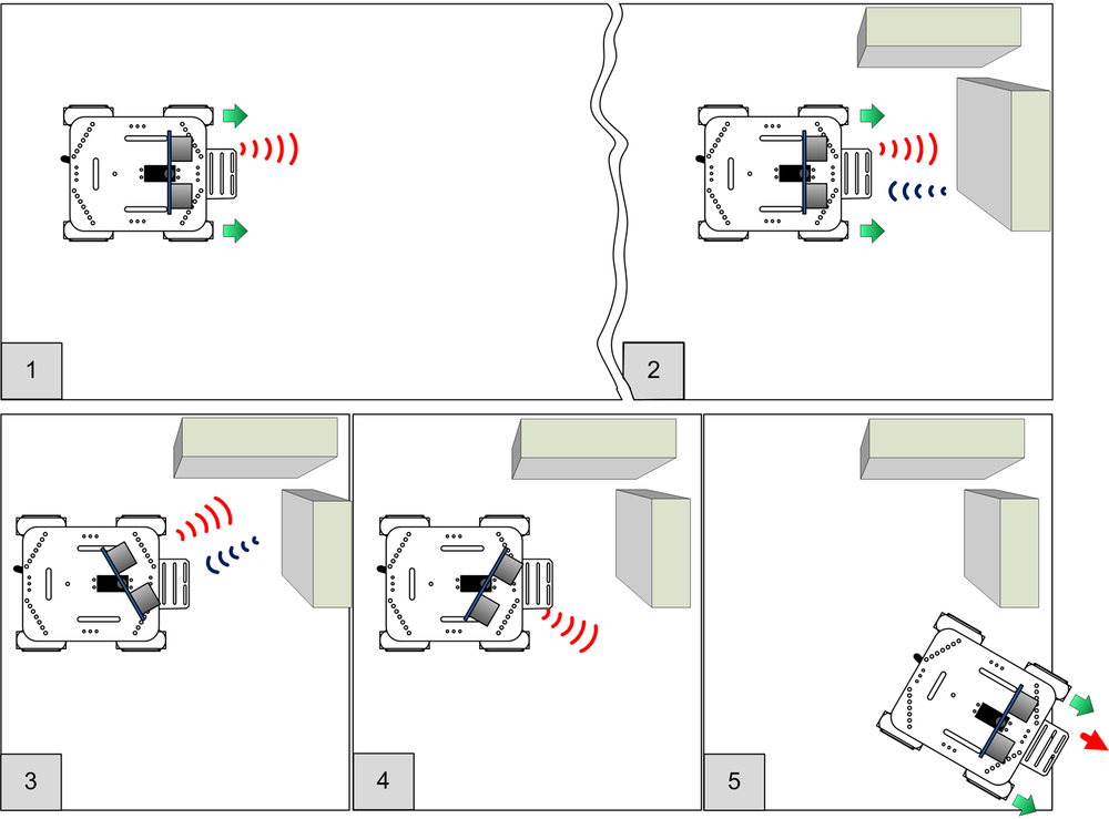
The sketch logic is the same, but the Look module has code added to
command a servo to rotate left and right for brief periods. This allows the sensor to look to
see if it can detect an obstacle (see Figure 10-15). If your distance sensor
is not centered, you can add a line in setup() that will center the servo. Example 10-6 shows the complete
setup function with the servo centering line added.
Example 10-6. The new setup function
void setup()
{
  Serial.begin(9600);
  blinkNumber(8); // open port while flashing. Needed for Leonardo only

  lookBegin();
  moveBegin();
  moveSetSpeed(MIN_SPEED + 10) ; // Run at 10% above minimum speed
  softServoWrite(90, 2000);      // Add this line to center the servo
  Serial.println("Ready");
}
The call to softServoWrite centers the servo and waits for two seconds.
If your sensor is not centered, follow these steps:
Switch the power off
Unscrew the servo shaft screw (see the instructions supplied with the Ping bracket)
Lift the Ping mounting bracket and reposition so it is facing forward
Replace the servo shaft screw
Power on and recheck
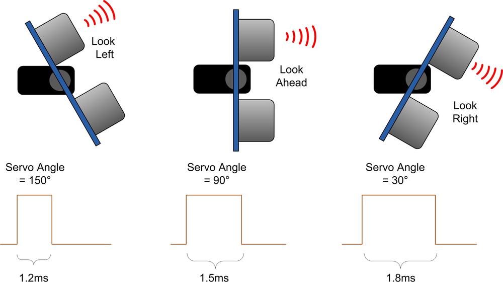
The servo angle is controlled by adjusting the pulse width on the Arduino pin connected to the servo. 1.5ms pulses will center the servo, and increasing or decreasing the pulse width will turn the servo one direction or the other.
Note
The exact relationship between pulse width and servo angle varies across different
servo products. If your servo turns right when it should turn left, swap the right and
left servo angles in the servoAngles array:
// servo angles             left, right, center
const int servoAngles[] = {  150,  30,   90};
Arduino has a Servo library that can control up to 12 servos, however this is not used in this sketch for two reasons. The Servo library enables you to send an angle to the servo and carry on executing sketch code while the servo is being moved in the background, but your code must wait until the servo is facing the desired direction before requesting a reading from the distance sensor. However, the main reason not to use the Servo library is because it requires exclusive use of one of the Arduino chip's hardware timers (timer 1) and timers are in short supply on a standard Arduino chip (see Appendix F).
The code to control the servo goes in a tab named Softservo (see Example 10-7).
Example 10-7. The code from the Softservo tab
/*******************************
 Softservo.ino
 software servo control without using timers
 note that these functions block until complete
*******************************/

int servoPin;

void softServoAttach(int pin)
{
   servoPin = pin;
   pinMode(pin, OUTPUT);
}

// writes given angle to servo for given delay in milliseconds
void softServoWrite(int angle, long servoDelay)
{
  int pulsewidth = map(angle, 0, 180, 544, 2400); // width in microseconds
  do {
    digitalWrite(servoPin, HIGH);
    delayMicroseconds(pulsewidth);
    digitalWrite(servoPin, LOW);
    delay(20); // wait for 20 milliseconds
    servoDelay -= 20;
  } while(servoDelay >=0);
}
The softServoAttach function stores the pin number that the servo is
attached to. The softServoWrite function converts the desired angle into a
pulse width and creates the pulse using digitalWrite with a pulse width
determined by a call to delayMicroseconds. The pulses are sent repeatedly
for the duration of the given servoDelay which is a period sufficient for
the servo to turn to the desired direction.
The Look code is similar to the code described at the beginning of this
chapter, but here the lookAt function calls
softServoWrite to rotate the servo instead of rotating the entire robot.
Example 10-8 shows the Look tab used in the myRobotScan
sketch.
Example 10-8. The modified Look tab code
/**********************
 code to look for obstacles
**********************/

// servo defines
const int sweepServoPin = 9;  // pin connected to servo
const int servoDelay    = 500; // time in ms for servo to move

const int  MIN_DISTANCE = 8;     // robot stops when object is nearer (in inches)
const int  CLEAR_DISTANCE = 24;  // distance in inches considered attracive to move
const int  MAX_DISTANCE = 150;   // the maximum range of the distance sensor

// servo angles             left, right, center
const int servoAngles[] = {  150,  30,   90};

const byte pingPin = 10; // digital pin 10

void lookBegin()
{
  irSensorBegin();    // initialize sensors
  softServoAttach(sweepServoPin);  /// attaches the servo pin to the servo object
}

// returns true if the given obstacle is detected
boolean lookForObstacle(int obstacle)
{
  switch(obstacle) {
     case  OBST_FRONT_EDGE: return irEdgeDetect(DIR_LEFT) && irEdgeDetect(DIR_RIGHT);
     case  OBST_LEFT_EDGE:  return irEdgeDetect(DIR_LEFT);
     case  OBST_RIGHT_EDGE: return irEdgeDetect(DIR_RIGHT);
     case  OBST_FRONT:     return  lookAt(servoAngles[DIR_CENTER]) <= MIN_DISTANCE;
  }
  return false;
}

// returns the distance of objects at the given angle
int lookAt(int angle)
{
  softServoWrite(angle, servoDelay ); // wait for servo to get into position

  int distance, samples;
  long cume;
  distance = samples = cume = 0;
  for(int i =0; i < 4; i++)
  {
    distance = pingGetDistance(pingPin);
    if(distance > 0)
    {
      //  printlnValue(" D= ",distance);
      samples++;
      cume+= distance;
    }
  }
  if(samples > 0)
    distance = cume / samples;
  else
    distance = 0;

  if( angle != servoAngles[DIR_CENTER])
  {
    Serial.print("looking at dir ");
    Serial.print(angle), Serial.print(" distance= ");
    Serial.println(distance);
    softServoWrite(servoAngles[DIR_CENTER], servoDelay/2);
  }
  return distance;
}

// function to check if robot can continue moving in current direction
// returns true if robot is not blocked moving in current direction
// this version only tests for obstacles in front
boolean checkMovement()
{
  boolean isClear = true; // default return value if no obstacles
  if(moveGetState() == MOV_FORWARD)
  {
    if(lookForObstacle(OBST_FRONT) == true)
    {
       isClear = false;
    }
  }
  return isClear;
}

// Look for and avoid obstacles using servo to scan
void roam()
{
  int distance = lookAt(servoAngles[DIR_CENTER]);
  if(distance == 0)
  {
    moveStop();
    Serial.println("No front sensor");
    return;  // no sensor
  }
  else if(distance <= MIN_DISTANCE)
  {
    moveStop();
    //Serial.print("Scanning:");
    int leftDistance  = lookAt(servoAngles[DIR_LEFT]);
    if(leftDistance > CLEAR_DISTANCE)  {
   //   Serial.print(" moving left: ");
      moveRotate(-90);
    }
    else {
      delay(500);
      int rightDistance = lookAt(servoAngles[DIR_RIGHT]);
      if(rightDistance > CLEAR_DISTANCE) {
      //  Serial.println(" moving right: ");
        moveRotate(90);
      }
      else {
       // Serial.print(" no clearence : ");
        distance = max( leftDistance, rightDistance);
        if(distance < CLEAR_DISTANCE/2) {
          timedMove(MOV_BACK, 1000); // back up for one second
          moveRotate(-180); // turn around
        }
        else {
          if(leftDistance > rightDistance)
            moveRotate(-90);
          else
            moveRotate(90);
        }
      }
    }
  }
}

// the following is based on loop code from myRobotEdge
// robot checks for edge and moves to avoid
void avoidEdge()
{
   if( lookForObstacle(OBST_FRONT_EDGE) == true)
  {
     Serial.println("left and right sensors detected edge");
     timedMove(MOV_BACK, 300);
     moveRotate(120);
     while(lookForObstacle(OBST_FRONT_EDGE) == true )
        moveStop(); // stop motors if still over cliff
  }
  else if(lookForObstacle(OBST_LEFT_EDGE) == true)
  {
     Serial.println("left sensor detected edge");
     timedMove(MOV_BACK, 100);
     moveRotate(30);
  }
  else if(lookForObstacle(OBST_RIGHT_EDGE) == true)
  {
     Serial.println("right sensor detected edge");
     timedMove(MOV_BACK, 100);
     moveRotate(-30);
  }
}
The lookForObstacle and roam functions are
modified from the non-scanning version to use the appropriate servo angles for looking left,
right, and center. The servo angles are stored in the array servoAngle
(swap the left and right values if your servo turns in the wrong direction). The
lookAt function now rotates the servo to the desired angle instead of
moving the entire robot.