Sensor information can be used by your robot to navigate and interact with its environment. Sensors report on the world around them; measuring light, distance, sound, movement, direction, temperature, pressure, or location. This chapter describes how common sensors used with two wheeled and four wheeled platforms work.
The first half of this chapter covers the primary sensors used in the chapters that follow: IR reflective sensors and SONAR distance sensors. These are used to determine if an object is near the robot. Reflective sensors detect nearby objects and are used for line following and edge detection (determining if the robot is near the edge of the surface it is moving on, such as the edge of a table). Distance sensors are used to determine the distance to objects up to ten feet away from the robot. The second half of the chapter covers other types of sensors you can add to enable the robot to respond to distance, sound, movement, or other stimuli. You should also have a look at Appendix D which describes a very useful aspect to sense, the robot's battery voltage.
- QTR-1A reflectance sensors
Two are used for edge detection, but a third is required for line following. Additional sensors are available from many internet shops that stock robot parts, or direct from the manufacturer: http://www.pololu.com/catalog/product/958/
- SONAR Distance Sensor
One is used to measure the distance to obstacles (Maker Shed product code MKPX5).
- Maxbotix EZ1 distance sensor
This is an optional item that can be used to measure distance.
- Sharp IR
This is an optional item that can be used to measure distance.
- PIR (Passive Infrared) sensor
This is an optional item that can be used to activate the robot when it detects the presence of a 'warm body' (Maker Shed product code: MKPX6).
- Sound Sensor
This is an optional item that can activate the robot on a sound level, such as a hand clap. (SparkFun product code BOB-09964).
The chapter contains background information on sensors that will be added to the robot in later chapters. The reflectance sensor code is from the sketches introduced in Chapter 6, Testing the Robot's Basic Functions. The Ping (Sonar distance sensor) hardware and software is covered in Chapter 10, Autonomous Movement.
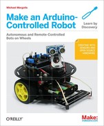
These sensors use reflected infrared light to detect the presence of a line for line following, or the absence of a reflection for edge (cliff) detection.
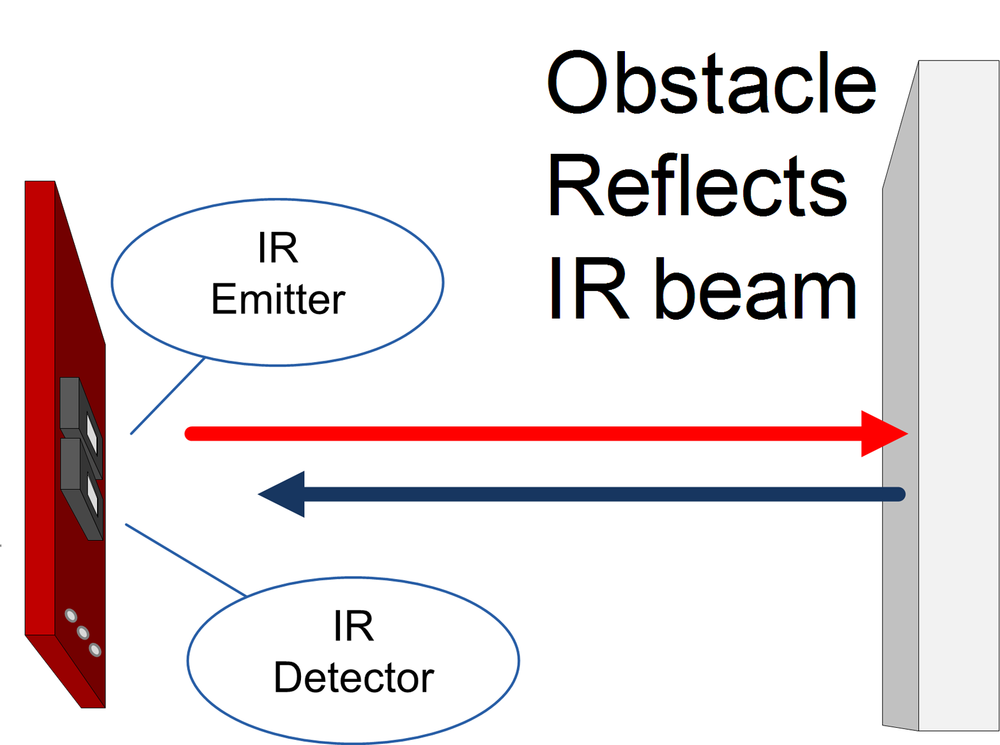
The robot uses a function named irSensorDetect, shown
in Example 8-1 to return true if the light level has increased
sufficiently above the ambient level indicating that a nearby object is reflecting the IR
beam.
Example 8-1. Detecting an obstacle that reflects light
const byte NBR_SENSORS = 3;  // this version only has left and right sensors
const byte IR_SENSOR[NBR_SENSORS] = {0, 1, 2}; // analog pins for sensors

// returns true if an object is detected on the given sensor
// the sensor parameter is the index into the sensor array
int irSensorDetect(int sensor)
{
  boolean result = false; // default value
  int value = analogRead(IR_SENSOR[sensor]); // get IR light level
  if( value <= irSensorReflect[sensor]) {
    result = true; // object detected (lower value means more reflection)
    if( isDetected[sensor] == false) { // only print on initial detection
      Serial.print(locationString[sensor]);
      Serial.println(" object detected");
    }
  }
  isDetected[sensor] = result;
  return result;
}
Sensor constants determine which sensor to use: SENSE_IR_LEFT for the
left sensor, SENSE_IR_RIGHT for the right (these constants are defined in
robotDefines.h (see Making the Sketch Easy to Enhance). The
irSensorDetect function uses the sensor constant to retrieve the analog
pin number stored in the IR_SENSOR array. If the analogRead value is less than a predetermined threshold, the
function returns true indicating that a reflection has been
detected. These functions use arrays instead of simple variables to store pins and thresholds
because arrays make it easy to extend the code to support any number of sensors. To add a
sensor, increase the NBR_SENSORS constant and add the sensors pin number to
the list of pins in the IR_SENSOR array.
Note
The sensor voltage reduces with increased light, so lower readings mean more reflectance. Therefore, the closer a reflecting object is to the sensor, the lower the reading on the analog pin monitoring the sensor.
Whereas irSensorDetect returns true when a
reflection is detected, sometime you want the opposite case—to return true if an edge (no
reflection) is detected, as in Example 8-2. The irEdgeDetect provides this capability; it is used to return true when an edge is
detected. In other words, when the sensor is looking downwards, no reflection from the surface
is detected because a dark object is blocking the reflection or the nearest surface—probably
the floor—is many inches away! This effect is used in the examples from Chapter 6 to detect when you've placed a dark object under the sensor.
Example 8-2. Detecting the absence of a reflection
boolean irEdgeDetect(int sensor)
{
  boolean result = false; // default value
  int value = analogRead(IR_SENSOR[sensor]); // get IR light level
  if( value >= irSensorEdge[sensor]) {
    result = true; // edge detected (higher value means less reflection)
    if( isDetected[sensor] == false) { // only print on initial detection
      Serial.print(locationString[sensor]);
      Serial.println(" edge detected");
     }
  }
  isDetected[sensor] = result;
  return result;
}
The sensors need to be calibrated to take ambient light into account. Reflectance sensors respond to sunlight and artificial light so a threshold is measured with no object near the sensor. Levels above this threshold mean the light level is above ambient, which indicates that a nearby object is reflecting the IR light from the sensor. Ambient light calibration is done using the code shown in Example 8-3.
Example 8-3. Light calibration
// calibrate thresholds for ambient light
void irSensorCalibrate(byte sensor)
{
   int ambient = analogRead(IR_SENSOR[sensor]); // get ambient level
  irSensorAmbient[sensor] = ambient;
  // precalculate the levels for object and edge detection
  irSensorReflect[sensor] = (ambient * (long)(100-irReflectThreshold)) / 100;
  irSensorEdge[sensor]    = (ambient * (long)(100+irEdgeThreshold)) / 100;
}
Note
(long) is used in the calculation to prevent overflow.
Values like 95000 cannot fit into an Arduino integer (max value is 32,767) whereas a long
can store values up to 2,147,483,647.
You may come across code that performs this calculation using floating point
(ambient * 0.95). However, floating point requires more code and memory
than integer calculations.
This loads the ambient light level into the variable ambient, calculates levels for reflectance detection (stored in the
irSensorReflect array) and levels for edge detection (stored in the
iresensorEdge array). The constant irReflectThreshold is the percentage difference in light to detect a reflecting
obstacle. The constant iredgeThreshold is the percent
difference to detect an edge. The default values for these thresholds are 10% for reflection
and 90% for edge detection.
Here is an example assuming the ambient value from analogRead was 1000 with
irReflectThreshold equal to 10 :
 (1000 * 90) / 100 =
  90000 / 100 =
  900
In this example, if the ambient reading was 1000, the irSensorReflect's threshold reading for object detection is 900, which is 10% below the ambient reading.
Sound pulses can be used to measure distance. The time it takes for a pulse to bounce off an object and return to the sensor is proportional to the distance.

The speed of sound is 340 meters per second, which means it takes 29 microseconds for
sound to travel 1 centimeter (the reciprocal of 340 metres per second). To derive the
distance in cm, the duration is divided by 29. The duration is the time for the sum of
outgoing and reflected pulses so the distance to the object is microseconds / 29 /
2.
The pulse duration is measured using the Arduino pulseIn function. This
returns the a pulse duration in microseconds, see http://arduino.cc/en/Reference/pulseIn.
Example 8-4 shows the code that uses the Ping sensor to return the distance in inches. You'll see this code in action in Chapter 10.
Example 8-4. The source code for the Ping sensor
/*********************************
 code for ping distance sensor
**********************************/

// Returns the distance in inches
// this returns 0 if no ping sensor is connected or the distance is greater than around 10 feet
int pingGetDistance(int pingPin)
{
  // establish variables for duration of the ping,
  // and the distance result in inches and centimeters:
  long duration, cm;

  // The PING))) is triggered by a HIGH pulse of 2 or more microseconds.
  // Give a short LOW pulse beforehand to ensure a clean HIGH pulse:
  pinMode(pingPin, OUTPUT);
  digitalWrite(pingPin, LOW);
  delayMicroseconds(2);
  digitalWrite(pingPin, HIGH);
  delayMicroseconds(5);
  digitalWrite(pingPin, LOW);

  pinMode(pingPin, INPUT);
  duration = pulseIn(pingPin, HIGH, 20000); // if a pulse does not arrive
                                            // in 20 ms then the ping sensor
                                            // is not connected
  if(duration >=20000)
    return 0;

  // convert the time into a distance
  cm = microsecondsToCentimeters(duration);
  return (cm * 10) / 25 ; // convert cm to inches
}

long microsecondsToCentimeters(long microseconds)
{
  // The speed of sound is 340 m/s or 29 microseconds per centimeter.
  // The ping travels out and back, so to find the distance of the
  // object we take half of the distance travelled.
  return microseconds / 29 / 2;
}
The pingGetDistance function returns the distance in inches as measured
with a ping sensor on the digital pin (pingPin) passed to the function. The sound pulse used to measure
the distance is triggered by sending a digital pulse that is low for 2 microseconds and high for 5
microseconds. The pin mode is changed from output to input and the pulseIn
function is used to measure the response from the sensor, which arrives as an incoming pulse width. The formula described at the beginning
of this section is used to convert this value to the distance.
Example 8-5 shows the code for the Maxbotix EZ1 SONAR distance sensor (pictured in Figure 8-3).

Example 8-5. Code for the EZ1 sensor
/********************************
  code for the EZ1 SONAR sensor
*********************************/
// return distance using EZ1 connected to analog pin
int ezDistanceAN(int pin) // using analog
{
   const int bitsPerInch = 2; // each bit is 0.5 inch
   int value = analogRead(pin);
   int inches = value / 2;
   return inches;
}

// return distance using EZ1 connected using PW
int ezDistancePW(int pin) //using digital pin
{
  int value = pulseIn(pin, HIGH); // timeout can be added (MAX_DISTANCE * 147L * 2)
  int cm = value / 58;      // pulse width is 58 ms per cm
  int inches = value / 147; // which is 147 ms per inch
  return inches;
}
The version using pulse width (ezDistancePW) will wait for one second
before giving up if no return pulse is detected (for example, if the sensor is disconnected).
You can optionally set the maximum time to wait for pulseIn; the following
example sets the timeout to the duration needed for a pulse to travel the maximum distance
detectable by the sensor:
int value = pulseIn(pin, HIGH, MAX_DISTANCE * 147L * 2);
// pulseIn with timeout
You can use the analog input version (ezDistanceAN), if you have a
spare analog input pin, but if you only have digital pins free, then use the pulse width code
(ezDistancePW). The analog version takes only as long as needed to
measure the voltage so does not need a timeout.
You can find more information on this sensor on the manufacturers web page: http://www.maxbotix.com/Ultrasonic_Sensors/MB1010.htm .
Example 8-6 shows the code for the Sharp GP2Y0A02YK0F long range IR distance sensor (pictured in Figure 8-4).

Example 8-6. Code for the Sharp IR sensor
/*********************************
 code for Sharp GP2Y0A02YK0F IR distance sensor
**********************************/
const long referenceMv = 5000; // the reference voltage in millivolts

int irGetDistance(byte pin)
{
  int val = analogRead(pin);
  int mV = map(val, 0, 1023, 0 , referenceMv);
  // or:
  //int mV = (val,  * referenceMv) / 1023;

  int cm = mvToDistance(mV);
  return cm;
}

// the following is used to interpolate the distance from a table
// table entries are distances in steps of 250 millivolts
const int TABLE_ENTRIES = 11;
const int firstElement = 250; // first entry is 250 mV
const int INTERVAL  = 250; // millivolts between each element
static int distance[TABLE_ENTRIES] = {200,130,90,64,50,41,35,30,25,20,15};

int mvToDistance(int mV)
{
   if( mV < firstElement )
      return distance[0];
   if( mV >  INTERVAL * TABLE_ENTRIES )
      return distance[TABLE_ENTRIES-1];
   else
   {
      int index = mV / INTERVAL;   // highest table element <= mV value
      int mV0 =  index * INTERVAL; // mV value of this element
      int mV1 = mV0 + INTERVAL;    // mV value of the next higher element
      int result = map(mV, mV0, mV1, distance[index-1], distance[index]);
      result = map(result, 0, 200, 0, 79); // convert from cm to inches
      return result;
   }
}
You can find lots more information on this sensor here: http://www.societyofrobots.com/sensors_sharpirrange.shtml .
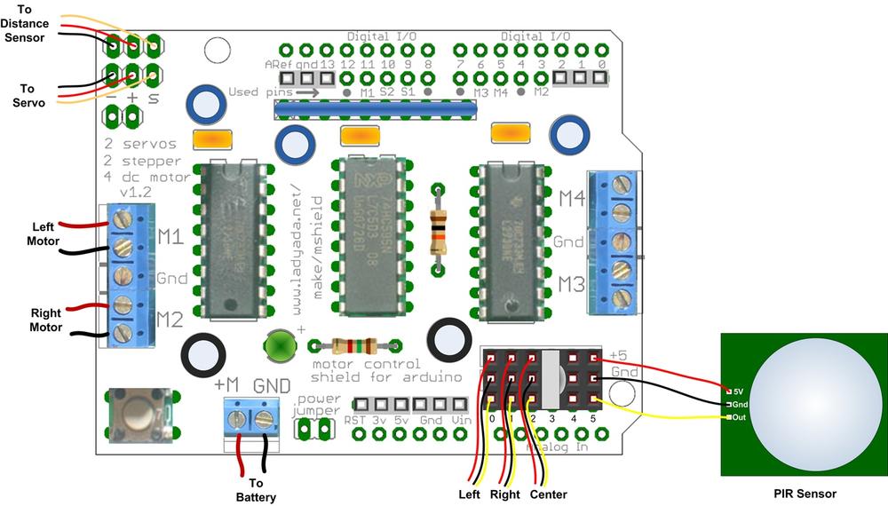
A PIR (Passive Infrared) sensor can be used to activate your robot when it detects the
presence of a nearby person, or even a dog or cat. The sensor acts like a switch that sends a
HIGH signal to an Arduino pin when motion is detected (they work by
detecting changes in the heat radiated from people or pets). Figure 8-5
shows the sensor connected to analog pin 5, but you can use any spare pin, such as
A4 instead of A5.
The following loop code will spin the robot when movement is detected.
If you want your robot to do this, replace the loop function in the
myRobot sketch from Making the Sketch Easy to Enhance with the
code shown in Example 8-7.
You can use a sound sensor to start or stop your robot in response to sound, for example a hand clap or whistle. You will need a microphone with an amplifier, for example, the BOB-09964 breakout board from SparkFun. Figure 8-6 shows the board connected to analog pin 4.

The code that follows is the main tab from the myRobotSound sketch
available in the download for this book. Noise level above a threshold will drive the robot
forward. The robot stops when the level drops below the threshold. If you need to change the
sensitivity, experiment with higher or lower values for the threshold. Example 8-8 shows the code for
the main tab.
Example 8-8. Sound sensor code
/**********************************************************
MyRobotSound.ino

Robot moves when a sound level exceeds a threshold
Based on Recipe 6.7 from Arduino Cookbook

Copyright Michael Margolis 20 July 2012

***********************************************************/

#include <AFMotor.h>  // adafruit motor shield library
#include "RobotMotor.h"    // 2wd or 4wd motor library

#include "robotDefines.h"  // global defines

const int analogInPin = 5;      // analog pin the sensor is connected to

const int middleValue = 512;      //the middle of the range of analog values
const int numberOfSamples = 128;  //how many readings will be taken each time

int sample;                       //the value read from microphone each time
long signal;                      //the reading once you have removed DC offset
long averageReading;              //the average of that loop of readings

long runningAverage=0;          //the running average of calculated values
const int averagedOver= 16;     //how quickly new values affect running average
                                //bigger numbers mean slower

const int threshold=400;        //at what level the robot will move

int speed = 50;

// Setup runs at startup and is used configure pins and init system variables
void setup()
{
  Serial.begin(9600);
  blinkNumber(8); // open port while flashing. Needed for Leonardo only

  motorBegin(MOTOR_LEFT);
  motorBegin(MOTOR_RIGHT);
}

void loop()
{
  int level = getSoundLevel();
  if (level > threshold)         //is level more than the threshold ?
  {
     motorForward(MOTOR_LEFT, speed);
     motorForward(MOTOR_RIGHT, speed);
  }else
  {
     motorStop(MOTOR_LEFT);
     motorStop(MOTOR_RIGHT);
  }
}

// function to indicate numbers by flashing the built-in LED
void blinkNumber( byte number) {
   pinMode(LED_PIN, OUTPUT); // enable the LED pin for output
   while(number--) {
     digitalWrite(LED_PIN, HIGH); delay(100);
     digitalWrite(LED_PIN, LOW);  delay(400);
   }
}

int getSoundLevel()
{
  long sumOfSquares = 0;
  for (int i=0; i<numberOfSamples; i++) { //take many readings and average them
    sample = analogRead(analogInPin);     //take a reading
    signal = (sample - middleValue);      //work out its offset from the center
    signal *= signal;                     //square it to make all values positive
    sumOfSquares += signal;               //add to the total
  }
  averageReading = sumOfSquares/numberOfSamples;     //calculate running average
  runningAverage=(((averagedOver-1)*runningAverage)+averageReading)/averagedOver;

  return runningAverage;
}
See the Arduino Cookbook if you want a detailed description of how this code works.
For descriptions of how to use lots of additional sensors with Arduino, see: Arduino Cookbook by Michael Margolis (O’Reilly).