
The sheet-metal functionality in Inventor is extremely powerful, centered around productivity and capturing your manufacturing intent. When you first begin working in the sheet-metal environment, you may feel overwhelmed; however, a mastery of some basic fundamentals can make Inventor sheet metal straightforward and highly integrated with your manufacturing environment.
In this chapter, you'll learn to:
Take advantage of the specific sheet-metal features available in Inventor
Understand sheet-metal templates and rules
Author and insert punch tooling
Utilize the flat pattern information and options
Understand the nuances of sheet-metal iPart factories
Model sheet-metal components with non-sheet-metal features
Work with imported sheet-metal parts
Understand the tools available to annotate your sheet-metal design
Harvest your legacy sheet-metal styles into sheet-metal rules
The sheet-metal environment was introduced in Inventor R2. Since sheet-metal parts have so many unique requirements, such as flat patterns and manufacturing-specific features, a modified part document is used. The same .ipt file extension is also used, but the sheet-metal capabilities and data are added.
Sheet-metal design is driven by manufacturing considerations. A basic sheet-metal part consists of flat faces joined by bends. For cost-effective manufacturing, all the bends should be the same radius. If a company uses corner reliefs, they should be the same size and shape. The sheet-metal environment captures this information in a rule and leverages it during modeling. This saves you considerable time during design because the features automatically use the settings in the rule. If you have to make a change, such as a different material thickness or bend radius, you can select a different rule, and the part automatically updates.
Many sheet-metal parts are brackets or enclosures that are made to fit a particular assembly. The sheet-metal tools were designed to simplify the process of creating and updating models. For example, you can change a bend to a corner seam simply by right-clicking the bend in the browser and selecting Change To Corner from the context menu.
The Inventor sheet-metal environment contains numerous specialized tools to help you design components that follow your sheet-metal manufacturing guidelines and process restrictions. The following sections describe general feature classifications and capabilities that will provide you with a quick road map to the features. Once you understand how the features work, you will be able to build models that capture your design intent.
Out of all the sheet-metal features provided, only four of them create what is referred to as base features. Base features are simply the first features that appear in the feature history. The base features are as follows:
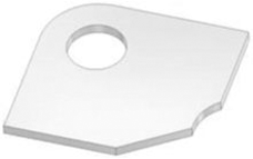
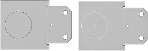
The Face tool is the simplest base feature; it utilizes a closed profile to produce a simple extrusion equal to the Thickness parameter value. The profile can be constructed out of any shape and can even contain interior profiles, as shown in Figure 6.1. Profiles for face features are often generated from the edge projections of planar faces or surfaces, and this capability enables numerous assembly-based and derived workflows.
The Contour Flange tool is a sketch-based feature (open profile) that has the ability to create multiple planar faces and bends as the result of a single feature, as shown in Figure 6.2. Profile sketches should contain only arcs and lines; if sketch intersections are not separated by an arc, a fillet will be automatically added at the intersection equal to the BendRadius parameter, which is driven by the sheet-metal style. To create base features with a profile sketch, contour flanges have a width extent option called Distance, which allows a simple open profile to be utilized to create a sheet-metal condition extrusion of the thickened, filleted profile.
You can use the Contour Flange tool to create sheet-metal parts; in fact, it is the fastest way to create them. It would be very time-consuming to create the individual faces for the part shown in Figure 6.2. Using the Contour Flange tool has one drawback, however: since you are combining many features, you lose some flexibility for revising the shape.
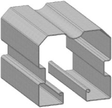
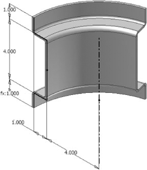
The Contour Roll tool is a variation on the Contour Flange tool. You sketch an open profile, but you revolve it instead of extruding it. Sketch geometry is limited to lines and arcs, and the Contour Roll tool will automatically add a bend at line intersections. The rolled hat flange in Figure 6.3 was created using the simple sketch geometry shown.
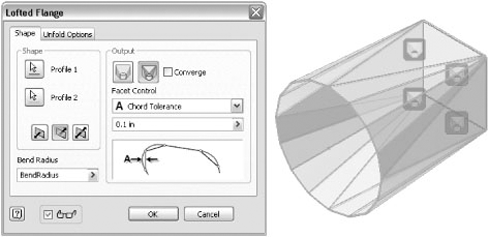
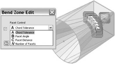
The Lofted Flange tool is a new feature for Inventor 2010. It creates sheet-metal transitions typically seen in HVAC and hoppers. See Figure 6.4 for a square-to-round transition. Basically, you create sketches of the beginning and end of the transition. The Lofted Flange tool gives you the option of a die form or a press brake transition. For press brake transitions, you can define the bends by chord tolerance, facet angle, or facet distance. The chord tolerance is the distance between the angled face and the theoretical curved surface. As the chord tolerance is decreased, more facets are added.
To create a lofted flange, follow these steps:
Click the Get Started tab, and choose Open.
Browse for the file named
mi_6a_001.iptlocated in the Chapter 6 directory of the Mastering Inventor 2010 folder, and click Open.Click the Lofted Flange icon in the Create panel.
Select the square and the circle for the profiles.
In the output area of the dialog box, click the Die Formed icon, and note that the preview changes to remove the press brake facets and that the facet controls are hidden.
Click the Press Brake icon, and then change the chord tolerance to .05inch.
Use the drop-down to experiment with the Facet Angle and Facet Distance options to familiarize yourself with their behavior.
Clicking one of the Bend Zone Edit glyphs displays a dialog box to change the facet control and also displays individual glyphs for each bend. The Bend Zone Edit dialog box enables you to change the facet control for that corner, as shown in Figure 6.5. Clicking one of the bend glyphs displays a Bend Edit dialog box that enables you to override the bend radius and unfold rule for an individual bend.
Click the check box, and select Number Of Facets.
Enter 5 in the edit field, and note the preview updates.
Click one of the Bend Edit glyphs, and change the bend radius to BendRadius*2.
Click OK, and note that the Bend Edit glyph has changed. A pencil is added to indicate that it has been overridden.
Click OK in the Bend Zone Edit dialog box. Hover your mouse pointer over the glyph, and note that a pencil has been added.
Click OK in the Lofted Flange dialog box.
Click the Create Flat Pattern icon on the Sheet Metal tab. Note that the part isn't flattened because it is a continuous piece.
Click the Go To Folded Part icon on the Sheet Metal tab to return to the sheet-metal modeling environment.
Select View Face in the navigation bar, and click one of the large transition faces in the graphics area.
Right-click the transition face, and select New Sketch. Manually project the face into the sketch if the Autoproject option isn't turned on.
Click the Point icon in the Draw panel of the Sketch tab, and click the midpoint of the projected base of the triangular face.
Right-click and select Finish Sketch from the context menu, or click the Finish Sketch icon on the Sketch tab.
Click the Rip icon in the Modify panel on the Sheet Metal tab.
Select the transition face you sketched for the rip face and the tip of the triangle. Note that the preview shows that the bend will be ripped.
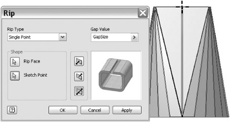
Click the Sketch Point button, and select the sketch point on the base of the triangular face. The preview should look like Figure 6.6.
Click OK to create the rip.
Double-click Flat Pattern in the Model browser. Note that the transition is now flattened.
Several sheet-metal tools create flanges, which are simply planar faces connected by a bend. The Flange tool automatically creates bends between the flanges and the selected faces. You can also use the Contour Flange tool to create several flanges at once. The Hem tool allows you to create specialized flanges to hem sharp edges or to create rolled flange features. Another tool commonly used along with these tools is the Face tool. Depending on the selected tool, you can either control options or allow Inventor to apply predefined relationships and values.
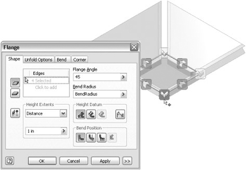
The Flange tool creates a single planar face and bend for each edge selected with controls for defining the flange height, bend position, and relief options at the edge intersections. For flanges referencing a single edge, width extent options are also available by clicking the >> button in the Flange dialog box. If multiple edges have been selected for flange locations, corner seams are automatically added, as shown in Figure 6.7. The bend and corner seam dimensions follow the sheet-metal rule. The preview displays glyphs at each bend and corner seam. If you click a glyph, a dialog box displays so you can override the values.
In addition to creating base features, the Contour Flange tool can also be used to add flanges. Since the Contour Flange tool uses open profile sketches, it is ideal for quickly creating complex shapes and enclosures designs. As discussed earlier, the Contour Flange tool can either automatically fillet line intersections or use sketched arcs for bends. Contour flanges automatically create a bend between the contour flange and a selected edge on an existing face. The sketch profile for the Contour Flange tool does not need to be coincident with the edge; it simply needs to be sketched on a plane that is perpendicular to it. If the sketch profile is coincident with an edge, a bend will automatically be positioned to connect the sketch profile to the face. If the sketch is not coincident with a reference edge and the width extent option is changed to Distance, the result will be a contour flange that isn't attached to the part.
Just like in the Flange feature, automatic mitering of adjacent flanges and the placement of corner reliefs, as shown in Figure 6.8, occur when multiple edges are selected.
The Hem tool is like a contour flange because it has the ability to create multiple planar faces and bends for a selected edge, but it is restricted to predefined common hem profiles and geometric relationships. Hem does not support the selection of multiple edges, but it does contain the full array of width extent customization options if you click the >> button.
The last feature capable of creating flanges is the Face tool. The Face tool uses a closed profile sketch, and it can automatically create an attaching bend to a selected edge. This automatic case is very powerful because it allows you to create a skeletal surface model of your design, project the planar surfaces into sketches, and create face features with attaching bends. The manual controls can be utilized to connect face features to preexisting geometry, create double bends (joggles), or even deselect edges that have been automatically inferred because they share a common edge.
You can also use the Face tool to create models from 2D flat patterns that had been created in another application such as AutoCAD. By importing the 2D flat pattern, the Face tool can be used to thicken it to the desired value. A flat pattern can be produced for a planar face (no unfolding needs to actually occur), which enables the use of special translation tools, Drawing Manager consumption, and a variety of other uses.
Once the general shape of a sheet-metal component is roughed in, material will need to be either removed or deformed in almost every design. Several sheet-metal-specific features have been created to optimize these workflows because most sheet-metal manufacturing operations (punch presses, for example) create features perpendicular to the surface. The current capabilities of Inventor assume that these manufacturing operations are done in the flat prior to folding and therefore should not interfere with unfolding (Inventor does not support post-folding manufacturing operations such as gussets, for example).
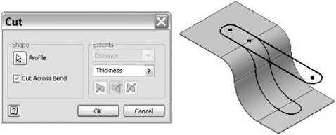
The Cut tool is a special sheet-metal extrude. It creates a hole based on a sketched profile. The Cut tool was created to help simplify the options of the regular Extrude tool. For example, the distance parameter defaults to Thickness. The Cut tool can also wrap the sketch profile across planar faces and bends, as shown in Figure 6.9. This option is particularly helpful because it allows you to force a uniform cut across multiple planar faces and bends with a value greater than zero and equal to or less than Thickness.
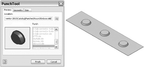
You can use the Punch tool to either remove material or deform it by placing predefined Punch tool geometry, as shown in Figure 6.10. Punches are special versions of iFeatures; they can be predefined with additional manufacturing information and can be built using a variety of standard and sheet-metal features. The "Authoring and Reusing Punches" section discusses punch features in detail.
Corner Round and Corner Chamfer are special sheet-metal tools that allow you to remove or break edges similar to filleting and chamfering. Edge selection has been optimized within the two tools, filtering out edges that are not normal to the sheet top and bottom faces for easy application.
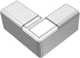
The Corner Seam tool allows you to extend (as shown in Figure 6.11) or trim flange faces in order to manage the seam between them and select corner relief options. The Corner Seam dialog box contains numerous options for specifying the seam and contains two fundamentally different distance definition methods: Maximum Gap and Face/Edge. Prior to Inventor 2009, only the Face/Edge method was available for the Corner Seam tool. The face/edge method works for many situations but also tends to suffer from an inability to maintain a constant seam gap between planar faces that do not have an identical input angle. The maximum gap method was developed from the perspective of a physical inspection gauge, where the nominal value of the seam is exactly the value entered at every point; you just might need to twist the tool as you draw it through the seam.
The Fold tool enables you to design a flange with a unique profile by allowing you to sketch the position of the bend centerline on a planar face, as shown in Figure 6.12.
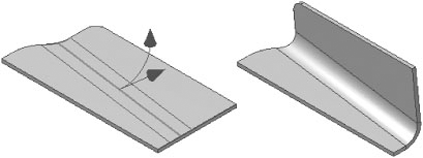
This tool is a sketch consumption feature and contains numerous controls for specifying exactly how a planar face should be manipulated into two planar faces connected by a bend. The sketch bend centerline must be coincident with the face extents, requiring you to project edges and constrain the sketch. When utilizing the Fold tool, remember that the feature works from the opposite design perspective of other sheet-metal features, where bend allowance is actually consumed, not added to the resulting folded feature. The Fold tool can be combined with the Face tool to help import preexisting 2D flat patterns and then deform them into their final shape.
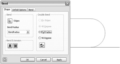
The Bend tool allows you to connect two planar faces by selecting a pair of parallel edges. Since Inventor supports the modeling of multiple lumps, the Bend tool can add either a single bend or a double bend (joggle) depending on the number of selections you make. For design situations in which multiple lumps have been produced, the Bend tool is often used to combine the lumps into a single body.
There are four possible double bend results, depending on the orientation of the edges and which option you choose. If the sheet-metal edges face the same direction, then either a full round bend, as shown in Figure 6.13, or two bends connected with a face is created. If the sheet-metal edges face in opposite directions, then a joggle is created with either two 45-degree bends and one edge fixed or both edges fixed and the angle calculated. In both cases, the faces will be extended or trimmed as necessary to create the bends.
The following example demonstrates the ways double bends are created:
Click the Get Started tab, and choose Open.
Browse for the file named
mi_6a_002.iptlocated in the Chapter 6 directory of the Mastering Inventor 2010 folder, and click Open.Click the Bend icon in the Create panel.
Select the indicated edges on Face1 and Face2. Note the Full Radius and 90 Degree double bend controls are enabled.
Watch how the preview changes as you switch between the Full Radius and 90 Degree options and when you toggle the Flip Fixed Edge button.
Leave the options with the Full Radius selected and Flip Fixed Edge buttons deselected, and click the OK button.
Right-click and select Repeat Bend from the context menu.
Select the indicated edges on Face3 and Face4. Note the Fix Edges and 45 Degree double bend controls are enabled.
Watch how the preview changes as you switch between the Fix Edges and 45 Degree options and when you toggle the Flip Fixed Edge button.
Leave the options with the 45 Degree and Flip Fixed Edge buttons selected, and click the OK button.
The Rip tool creates a gap in a sheet-metal part. A common workflow is to create a transition with the Lofted Flange tool and then add a rip so it can be flattened. The Rip tool creates a gap that is cut normal to the selected face. The UI is optimized to create a simple gap with minimal inputs.
Inventor has three options for creating a rip:
- Single Point
If the corner of a face is selected as the single point, the rip will follow the edge. If a sketch point located on an edge is selected, then the rip will be perpendicular to the edge.
- Point To Point
For Point To Point, a linear rip is created between the two points.
- Face Extents
For face selection, all edges of the face are ripped.
The Unfold and Refold tools were added to Inventor 2010. These features allow you unfold and then refold the model. There are several reasons to do this:
To add features in the unfolded state
To refold the model in bend order to see the manufacturing stages of the part
To change the orientation of the folded model in space
One of the limitations in previous versions of Inventor was that you couldn't fold a deformation. For example, if you added a stiffening rib to a face, you couldn't fold that face later. You could use the Project Flat Pattern and Cut Across Bend tools to remove material, but the functionality was well hidden. Using Unfold or Refold, you can add a deformation that crosses the bend zone and then refold it. Since the deformation is simply calculated around the bend, there can be distortion issues when the deformation is large with respect to the bend radius. For best results, limit the deformation to the thickness. For larger deformations, make sure the final results match what would be created in the shop.
Many sheet-metal parts are complex, with several bend order possibilities. Using Unfold or Refold allows you to experiment with bend order so you can determine the best way to manufacture the part.
Changing the orientation of the folded model is an interesting workflow. When you unfold a model, you select a face that remains stationary. When you refold the model, you also have to select the stationary face. If you don't select the same face, the model will have a different orientation when you are done.
The flat pattern is a separate model object that shows the completely flattened part for documentation. The flat pattern also contains manufacturing information such as bend direction. Unfold and Refold features can't be directly accessed in the drawing, so you can't have views showing different states of the same model. To show intermediate fold states in a drawing, use derived parts to create models with refold features suppressed, and then create views of those models.
The Unfold/Refold process is straightforward. The selections have filters for the correct geometry, so you don't have to focus on a small target.
Click the Get Started tab, and choose Open.
Browse for the file named
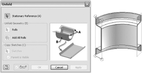
mi_6a_003.iptlocated in the Chapter 6 directory of the Mastering Inventor 2010 folder, and click Open.Click the Unfold icon in the Modify panel.
Select the blue face on the part.
Select all the bends on the folded model. Each bend will highlight when you hover your mouse pointer over it, so you know when you have a valid selection. The unfolded preview updates as you select each bend.
Click the Sketches button, and select the sketch in the graphics window.
Click OK. The model should look like Figure 6.14. Note that a copy of the sketch was placed on the unfolded model and that the original is still displayed as a reference.
Click Cut in the Modify panel.
Select the two rectangles in the copied sketch, and click OK.
Select the Model tab, and click Extrude.
Select the two rectangles in the copied sketch. Click the arrow in the depth field, select List Parameters, and select Thickness. Click the Bi-directional button, and click OK.
Select the Sheet Metal tab, and click Refold in the Modify panel.
Select the red face on the part.
Click the Add All Bends button to automatically select all the bends.
Click OK. Note that the model is in a different position, since the red face was kept stationary. Also note that the sketch geometry is out in space. Since Inventor is a history-based modeler, the sketch is referencing the original location of the face. If you drag the end-of-part (EOP) marker above the Unfold feature, the model will be in its original position.
You can also Unfold or Refold a contour roll. If the tools detect that the part is a contour roll, work planes are displayed on each end face. Since a flat reference face is required, you can select one of the work planes and then unfold the contour roll, as shown in Figure 6.15.
A well-hidden segment of sheet-metal–specific functionality is a special version of sketch projection called Project Flat Pattern (nested at the end of the sketch projection flyout). Project Flat Pattern is available from the folded model environment and is utilized to include the projected edges of the flattened sheet-metal component, oriented to the sketch plane that is active. This option is very powerful when combined with the Cut Across Bend option because it allows you to create parametric dimensions and constrained relationships from the perspective of the flattened sheet. When utilizing the Project Flat Pattern option, it isn't necessary to select every face; just pick the ones at the extremities (ensuring that they're on the same flattened side of the part as your sketch), and all the connecting planar faces and bends will automatically be included.
Inventor offers the ability to create sheet-metal rules that can be stored in the Inventor style library. If you aren't new to sheet-metal work, you might be wondering why this is a big deal since the sheet-metal environment has always had great style support and definition capabilities by using special-case, template-based styles. The simple answer is that the move to the style library makes sheet-metal definition information more manageable, reusable, and powerful.
The new sheet-metal rules (added to Inventor in the 2009 release) are a direct evolutionary step from the template-based sheet-metal styles that were available in releases prior to 2009. The sheet-metal environment uses the predefined information within sheet-metal rules to apply design and process information to your sheet-metal component. Sheet-metal rules have the ability to capture design intent that may not affect your component currently (such as bend transitions, relief options, and so on) but could be applied when necessary during the parametric design and editing process. Sheet-metal rules are referenced by sheet-metal features to help predefine their values and options based upon your manufacturing requirements.
This capability really makes sheet metal the only true rule-based design environment within the standard Inventor product suite. Sheet-metal rules differentiate themselves from sheet-metal styles in that their information can be published to a style XML file. One benefit of library-based styles/rules is that their definition information can be pulled into your design only when necessary, allowing your document to remain as light as possible and devoid of unneeded style information. Changing the style library architecture has also enabled a broadening of access to sheet-metal rule information, allowing specialized sheet-metal unfolding rules to be drawn into your design from within feature dialog boxes but no longer requiring predefinition within a style interface.
As an example of some of these enhancements, prior to Inventor 2009 many sheet-metal customers would create a sheet-metal template that contained all the styles used by a company. This template-based process often meant that as many as 30 sheet-metal styles would be embedded into a sheet-metal component even though only one would be set as the active style. The style tools allow you to select the sheet-metal rule you want to use, and that rule (and its associated material style and unfold rule) will exclusively be drawn into the sheet-metal document for use during the design process. Once the style information is drawn in, it gets stored in the local document and resides there until you decide to purge it.
Before Inventor 2009, sheet-metal templates were exclusively used to define sheet-metal design and manufacturing preferences (sheet-metal styles). The sheet-metal styles were organized in a simple format, where the sheet-metal style was dominant and material styles could be linked to the sheet-metal style, but the relationship was parent-child. Additionally, unfolding preferences (that is, K-factor or bend table) as well as sheet thickness information were also driven by the selection of a specific sheet-metal style. The sheet-metal styles have been replaced with style library sheet-metal rules, but the familiar parent-child relationships established in previous releases continue to be organized in the same order; they're just a little more sophisticated.
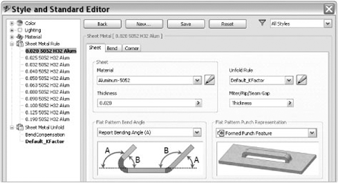
When you first look at the sheet-metal rule within the Style And Standard Editor dialog box (as shown in Figure 6.16), you will notice that the general layout is almost identical to that of the legacy Sheet Metal Styles dialog box. The linked material style (the Material value) and the Thickness value are prominently located at the top of the Sheet tab. The Unfold Rule drop-down list is used to predefine a linked sheet-metal unfold rule, which we'll talk about it in more depth later in this chapter. The Bend and Corner tabs aren't changed except for the move to a new home.
If you are migrating from an older version of Inventor, nothing is stopping you from using your templates in the same way as you have used them in the past. Some customers may not like the idea of using a style library and still prefer the familiarity of template-based deployments in which all the style information is populated into a sheet-metal template, and this workflow is still completely supported. Although the interface has changed a little, editing values in the Style And Standard Editor dialog box affect only those values stored in the active document, because Inventor does not automatically edit the style library files. So, although the interface has changed from a Sheet Metal Styles dialog box to a category within the Style And Standard Editor dialog box, edits to rules still affect only the active document.
Another change to the way you can interact with sheet-metal rules is facilitated by the introduction of the Sheet Metal Defaults dialog box, as shown in Figure 6.17. In previous releases, the icon located at the top of the Sheet Metal Features panel bar was used to access the Sheet Metal Styles dialog box. This tool has been replaced with a new one that brings up a small dialog box that reflects the current state of styles, rules, and options being applied to your sheet-metal design.
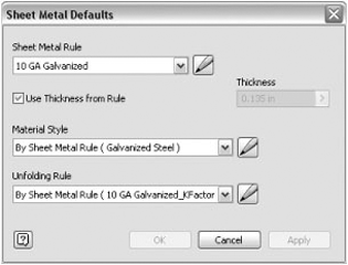
You can use the Sheet Metal Defaults dialog box for a number of purposes. For example, you can use it to directly access and draw into your document new styles/rules, you can use its edit buttons to navigate to the Style And Standard Editor categories, and you can use it to perform document-level overrides of styles, rules, and thickness values. As a best practice, it's suggested that you allow the sheet-metal rule to control all the information in the Sheet Metal Defaults dialog box, meaning you should allow the thickness to be driven by the referenced sheet-metal rule as well as use the By Sheet Metal Rule setting for defining the material style and unfold rule. It's also important to remember that the preferences set within the Sheet Metal Defaults dialog box affect the document; this means that whatever state the dialog box is in when you save will be persisted within the document when you reopen it in the future. If you are creating a template file and overrides have been selected within the Sheet Metal Defaults dialog box, when referencing the template file in the future to create a new design, it will start with those overrides in place. Changing the active sheet-metal rule does not wipe the overrides in the Sheet Metal Defaults dialog box because these overrides are managed at the document level, not at the style library.
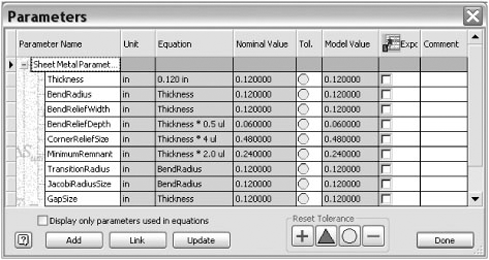
One mechanism used to drive manufacturing and design preferences into sheet-metal features is the association of sheet-metal rule values with Inventor parameters. In previous releases, these sheet-metal parameters had been exposed as regular model parameters, but this has changed with the switch from sheet-metal styles to rules. Sheet-metal parameters are now exposed within the parameter editor as special reference parameters, as shown in Figure 6.18. The one notable exception is the Thickness parameter, which can be changed from reference to model by deselecting the Use Thickness From Rule option box in the Sheet Metal Defaults dialog box. One reason for changing sheet-metal parameters into reference parameters was based upon a legacy ability to actually drive sheet-metal styles from the parameter editor edits. This practice sometimes caused stability issues when parameters were orphaned, but some workflows were actually very powerful. We'll briefly discuss this type of workflow in the "Harvesting Legacy Sheet-Metal Templates" section.
With the transition of sheet-metal styles into sheet-metal rules, sheet-metal unfolding options have also evolved and are now exposed as their own fully established rule category: sheet-metal unfold rules. Two unfolding options have been traditionally supported within Inventor: linear unfolding using a K-factor and bend tables that use experimentally derived bend deduction values. Both methods continue to be embraced within Inventor with some notable style library enhancements.
Before getting too deep into the unfold rule enhancements, an overview of the mechanics of unfolding might be helpful. Linear unfolding is accomplished by determining the bend allowance (the amount of material required to produce a bend) for a given bend by using the sheet thickness, the bend angle, the inner bend radius, and a K-factor value. For a given bend, there exists an offset surface position (within the bend cross section) that represents the neutral surface of the bend. The location of this neutral surface is most likely positioned somewhere between the 25th and 50th percentile of the cross section. The reason that this surface is referred to as the neutral surface is that it defines a measurable position within the bend that has the same length value in the folded and unfolded states. The K-factor is the ratio of the neutral surface position divided by the thickness of the sheet. The K-factor you use will depend on numerous factors, including material, thickness, and tooling. Most likely, you will need to perform a number of test bends on a specific press brake to determine the ideal K-factor for you. Out of the box, Inventor has an unfold rule example that utilizes a K-factor value of 0.44, which means the neutral surface is expected to be positioned 44 percent through the cross section of the bend.
The second unfolding method is accomplished by using sheet-metal bend tables. Bend tables support the refinement of your unfolding results by allowing you to customize the calculated developed length with experimentally determined values. Instead of using a constant K-factor value, bend tables enable you to customize the unfolding result for any combination of thickness, inner radius, and bend angle. The bend deduction values entered into the table are based upon a specific sheet thickness and are referenced to the coordinate intersection of inner bend radius and bend angle values. The granularity of the experimental values is up to you. It could be based upon 15-degree increments or perhaps 0.5-degree increments; it depends on how much experimental data you have. To create a bend table, you need to measure a sheet-metal sample prior to folding and then once again after folding. By measuring the folded sample using virtual sharp locations, the values obtained will inherently be too large. The overmeasurement of the test fold sample needs to be compensated for by deducting an amount of length. By subtracting your combined measurements from the initial measurement of the sample taken prior to folding, you will be able to determine the value of excessive length (overmeasurement); this is what gets entered into the bend table and is where the method name bend deduction comes from.
Within the Style And Standard Editor dialog box is a style rule category called Sheet Metal Unfold. Within the unfold rule dialog box, an Unfold Method drop-down list allows you to choose between creating a linear unfold rule and a bend table unfold rule. The linear rule is simple and requires only the definition of a K-factor value. The bend table unfold rule, however, uses a table for the bend deduction values. The dialog box, as shown in Figure 6.19, will allow you to see bend table information that was previously embedded in your document but not visible to you. Bend tables can be created manually by entering values or even copying and pasting data from Excel. The Import button located at the bottom-left corner of the Style And Standard Editor dialog box allows you to change the file extension to .txt so that legacy bend tables can be imported into Inventor and displayed within the unfold rule interface. As a final capability, Export Table not only supports the .xml file format, it also supports a .txt format in case you need to share your bend table with others using previous versions of Inventor.
The layout of the Bend Table interface emulates the data structure of the legacy .txt bend tables. It has provisions for setting the unit type of the bend table as well as the bend angle reference. These options are important to understand, because they do not change any data entered into your table; they simply change how the data is interpreted when used for unfolding. Changing the linear unit from inches to feet won't affect data, but it will dramatically reduce the amount of deduction applied to your developed length calculation.
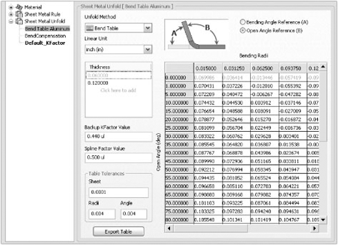
As a bit of odd history on the bend table, it was designed to reference an "open angle" datum structure (which is still default) for measuring bends, whereas Inventor sheet-metal features exclusively use a "bending angle" datum structure to create bent features. As a means to bridge this disparity in measurement convention, the Bend Angle option at the top of the Bend Table interface allows you to declare in which structure your values were measured; Inventor will use this option to convert the values internally if necessary. Just to reaffirm, the angular values are not altered within the table when this option is changed.
The Thickness list collection allows you to create a number of bend tables for a given material, where the selected Thickness value will direct which bend table is being edited or viewed. A Backup K-factor value is also stored within the bend table, which is used when a bend angle/bend radius combination exceeds the boundaries of the table for a given sheet thickness. You can imagine this like an insurance plan that allows you to obtain a flat pattern even if your bend table doesn't define what deduction to use for smaller or large combinations of bend angle and radius. For combinations that fall within the table boundaries but not exactly at angle/radius coordinate values, Inventor uses linear approximation to derive a value; depending on the change in bend compensation between steps in the table, you can achieve better results with smaller angle increments.
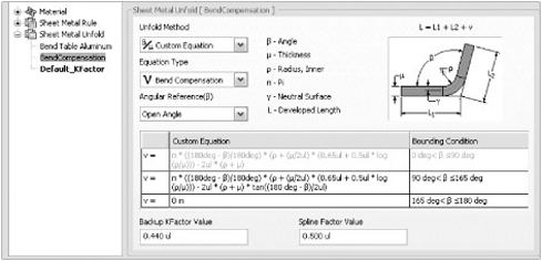
Inventor 2010 adds the ability to enter an expression for the bend compensation. Instead of entering values for specific bend angles and using linear interpolation between the values, you can enter ranges of bend angles that use an expression to determine the proper compensation within that range. The default bend style uses this method for the bend table. To access the Bend Compensation settings, go to the Manage tab, click the Style Editor button, and then expand the Sheet Metal Unfold node in the left pane. Finally, select BendCompensation. Figure 6.20 shows the BendCompensation settings.
If your project location is set to use the style library, then it is important to understand what has been defined within your template and what has been stored within the style library. As an example, if you have a sheet-metal rule named MyRule1 with the Thickness value equal to 0.2 stored in your template file and a sheet-metal rule named MyRule1 with the Thickness value equal to 0.5 stored in your style library, every time you start a new design from the template referencing MyRule1, you will see a Thickness value of 0.5 being applied.
The reason for this is that the style library is the "published" source of your standards; its definition will always win. After saving your design, if you want to make changes to the Thickness value of MyRule1, you can apply the changes without fear that they might be automatically overwritten, because this occurs only when creating a new document using the template. (As a side note, if you did want to overwrite the local/document definition with the style library's definition, right-clicking an existing rule will present a context menu from which you can select Update Style, which will manually refresh the rule's definition in the document.)
It is a good practice when using the style library to have perhaps a single sheet-metal rule embedded in your template file. Once you know what sheet-metal rule you want to apply to your model, selecting it either in the Style And Standard Editor dialog box or in the Sheet Metal Defaults dialog box will automatically draw the information into the active document. This process keeps extraneous information out of your document, providing a smaller footprint, and helps reduce the chance of style information mismatch. If you have a template file that has numerous sheet-metal rules stored within it, after publishing them to the style library, you can use the purge functionality with the Style Management Wizard to remove them.
The most common method to cost effectively cut or deform sheet metal is by using a punch machine. Since this process is so fundamental to the sheet-metal manufacturing environment, Inventor sheet metal contains a special Punch tool feature. Inventor punch tools are a specialized subtype of iFeatures that embody unique capabilities and a simplified placement process.
The process of creating a punch is almost identical to creating a standard iFeature, but you need to be aware of a few key differences. Different from regular iFeatures, punches require the inclusion of a sketch center point in the insertion sketch; this is the highest-level sketch consumed by a feature that you are including in the published punch feature. The iFeature extraction dialog box actually checks for the inclusion of this sketch point to ensure you don't go to the trouble of publishing punches that cannot be placed. After you have created your punch tool geometry, go to the Manage tab, and click Extract iFeature to begin the publishing process. Located at the top of the Extract iFeature dialog box is a type group that contains a Standard iFeature option and a special subtype Sheet Metal Punch iFeature option. Select the Sheet Metal Punch option when creating a punch iFeature.
The vast majority of the options in the iFeature extraction dialog box are generic to standard iFeatures and punches, but once you have selected the punch subtype option, you will see that the Manufacturing and Depth fields become enabled. Punch tools have the ability to store additional manufacturing information that is introduced during the creation process. The Punch ID field is where you can store a string that represents the Punch tool number.
The simplified representation selection control allows you to select a 2D sketch representation or symbol that you want to display in the flat pattern instead of the actual formed shape. The sketch must also contain a center mark so that it can be oriented with the punch's insertion center mark. The Punch Depth field is where you can enter a value that reflects the intended throw depth of your tool into the sheet face. For example, when creating a dimple or a half shear, you need to specifically call out a Punch tool depth to ensure that the formed feature turns out exactly as you expect. The Punch Depth field allows you to enter a value or even a parametric expression that specifies this tooling depth.
When deciding how to create the geometry and parametric relationships for your punch, you may want to follow a few guidelines to improve the potential for successful authoring, ease of placement, and the computational result. Creating successful punches (and iFeatures) takes a little longer than regular modeling since you're trying to anticipate conditions in which your tooling will be placed and establishing expectations of how it will react. The following sections touch on two areas that are commonly the root of punch problems.
Although it's a common practice to use work geometry to model features, this practice is never a good idea when creating punches (or iFeatures). The most problematic type of work geometry is the work plane, which has a defined normal direction that cannot be robustly persisted or recovered within the authored punch. Work planes are often ideal when modeling your punch tooling because you require a midplane in order to sketch a uniform cross section that can be swept. Sometimes a careful progression of additional features can help you compensate for this work plane requirement.
For example, in the process of creating a dimple, you might need to cut out material and then sweep a deformed cross section in its place. Instead of cutting out the entire round, cut out only half of the profile so that a planar detail face is created in the center. You can sketch your dimple cross section upon the detail face before cutting away the remaining half round. The dimple can be finished by sweeping the profile around the original cut profile. During this process, it's critical to remember that any projections or sketch references must exclusively be made to the top face, or unintentional orientation references might be inferred. This solution didn't require a work plane but utilized the same references that you might have obtained by creating one. Since all the features were based on the geometry originally defined from the punch's insertion face, the computation is stable.
Punch features (and iFeatures) consume parameters that can be utilized to vary the size of the families of punches or help adapt your punch to different conditions. Sheet metal in particular has a number of reference parameters that are guaranteed to be in any sheet-metal document since the sheet-metal rule ensures their creation. These parameters can be either useful or detrimental, depending on how you utilize them. For example, when we made the round cut while creating the dimple, we utilized the parameter Thickness to define its cut depth. In that case, this was a good idea since you would want the cut depth to be able to accommodate a variety of sheet thicknesses for which it might be placed upon in the future.
Defining the various radii in the dimple cross-section sketch is a very different situation. If you reference a sheet-metal parameter when creating the cross section, it might change significantly when utilizing different sheet-metal rules with a variety of sheet thicknesses. The tool may fail, since the value might change in unexpected ways that cannot be computed. Although tooling generally has well-known radius values, sometimes it seems convenient to define these values as a proportion of a parameter. Resist this practice, and choose all parameter values carefully.
Punch tools have a unique ability to change between formed and 2D representations in the flat pattern; this capability is enabled by a technology called alternate punch representations. To enable the alternate representation functionality, during the punch-authoring process you are afforded the opportunity to select a 2D sketch that depicts a representation you desire. The sketch geometry can be something similar to the formed geometry; it can be constructed of the projected edges of the formed geometry (this representation can change if it interacts with other features), or it can be a simple sketch that represents the Punch tool symbolically. To orient the 2D representation sketch to the insertion sketch of the Punch tool, you must insert a single center mark. You can in fact use the same sketch for both inserting the Punch tool and defining the alternate representation.
Regardless of whether the Punch tool represents removed or deformed material, the 2D alternate representation (2D Sketch, 2D Sketch And Center Mark, and Center Mark Only) can be displayed on the flat pattern in place of the actual punch, as shown in Figure 6.21.
To change the punch representation in a flat pattern, first ensure that you have the flat pattern set active for edits (right-click the Flat Pattern node and select Edit Flat Pattern), and then right-click the Flat Pattern browser node and choose Edit Flat Pattern Definition. Click the Punch Representation tab, and then choose the representation type from the drop-down. You may need to use the ViewCube to view the opposite side of the flat to see the 2D representation depending upon the specifics of how your punch was placed relative to your default orientation.
You can replace the formed punch with the simplified representation as long as it does not interfere with the outer contour/profile of the flat pattern. If the punch does intersect the flat pattern outer contour and a 2D alternate representation is selected, you will be prompted with a notification that will alert you to the fact that these punches could not be replaced. The punch alternate representation is set within the active sheet-metal rule within the options on the Sheet tab. The punch representation can also be overridden from within the flat pattern environment using the Flat Pattern Definition dialog box's Punch Representation tab controls.
The process of applying a published Punch tool to your sheet-metal design is fairly straightforward. In fact, the reason why Punch tools are special versions of iFeatures instead of standard iFeatures is to make the placement process faster and more reliable. As discussed in the previous section, when authoring a Punch tool, the first sketch-based feature referenced to create the Punch tool needs to contain a single sketched center mark. To place a Punch tool, another sketched center mark is all that is needed. To place a Punch tool, follow these steps:
Create a 2D sketch containing a sketched center mark.
Launch the Punch tool from the Modify panel of the Sheet Metal tab.
Once the Punch Tool Directory dialog box appears, select a Punch tool file from the catalog list.
Once you've selected the tool, the interface will change to the Punch Tool dialog box and display options for changing the punch, geometry, and size (if available within the punch definition); select Geometry.
On the Geometry tab, enter an angle to rotate the Punch tool preview.
Click Finish to create the iFeature.
You can use a few methods to pattern punches within a sheet-metal design. Since a sketched center mark (center point) is required for inserting the punch, you can create an array of center marks within a sketch to apply numerous punches at the same time. When you launch the Punch tool, it will attempt to automatically select all visible center marks in your sketch as long as only one sketch is visible. This method also allows you to utilize the Geometry tab, which "centers" selection control to either add center marks that were not participating or deselect center marks that you do not want a punch placed at, as shown in Figure 6.22. One powerful capability of patterned sketch center marks is the creation of irregular patterns that are produced by deselecting specific center marks in symmetric array. The sketched pattern method works, but it is limited to patterning within a single plane (2D sketch plane) and has some performance impacts when patterning large numbers of punches.
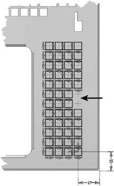
Figure 6.22. Sample back bracket folded model with irregular punch pattern created using center mark deselection of a symmetric sketch array
The second method for patterning punches is to insert a single punch feature and then use the rectangular or circular patterning features to create additional punch instances. Although the definition process is similar, you can create nonplanar arrays and achieve additional performance enhancements. When you click the >> button of the Rectangular Pattern and Circular Pattern dialog boxes, an option called Optimize is available. Whenever you are trying to pattern large numbers of punches, features, or iFeatures, this option should be enabled to improve performance. Irregular punch patterns can also be produced using this method but must be computed as a symmetric array first, and then individual child occurrences can be suppressed using the feature browser.
The flat pattern derived from the folded model ties the design to the manufacturing environment. Within Inventor, the flat pattern model is an actual flattened version of the folded model vs. a sheet that has been pieced together and thickened. Numerous tools, utilities, and data sources have been provided to enable the flat pattern to suit your individual manufacturing and documentation needs.
The flat pattern contains a wealth of manufacturing information that is stored progressively during the design process. Punch and bend information is stored within the flat pattern model specifically so that customers working with drawings, customers working with the API, or those who want to translate the flat pattern to a different file version can control all their options in a common location; the flat pattern is commonly referred to as the jump-off point for all downstream consumers.
The following sections detail these capabilities and tools.
The flat pattern environment has its own panel bar containing a customized set of modeling tools drawn from the Part Features panel bar and the Sheet Metal Features panel bar. The flat pattern tools are referred to as flat pattern edit features, because they are intended to apply small alterations to the flat pattern model instead of large-scale modeling. Flat pattern edit features are applied only to the flat pattern, whereas folded model features are applied first to the folded model and then carried over to the flat pattern. The flat pattern can be imagined as a derivative of the folded model, establishing a parent-child relationship (flat pattern edit features are not reflected in the folded model). There are many situations in which the generated flat pattern is not exactly what you need for manufacturing; flat pattern edit features are ideal for making small associative tweaks that previously required exporting the flat pattern to an external (disassociated) file.
Two new features in Inventor 2010 support adding manufacturing information to the flat pattern. The Bend Order Annotation tool enables you to specify the order in which bends are created. The Cosmetic Centerlines tool marks bend locations, such as cross brakes, where there is mild deformation.
- Bend Order Annotation
When you click the Bend Order Annotation icon in the Manage panel, the bends are automatically numbered. The context menu has two options for overriding the numbering: Directed Reorder and Sequential Reorder. Directed Reorder automatically renumbers any bends between two selected bend number glyphs. Sequential Reorder renumbers bends as you pick them. You can also renumber individual bends by double-clicking the number glyph. This allows you to renumber a few bends in a complex flat pattern. Inventor will automatically renumber the remaining bends in a flat pattern, but any bend numbers that are already overridden will not update. As a result, you need to renumber the largest series of bends first and then manually renumber any remaining bends.
- Cosmetic Centerlines
Cosmetic Centerlines capture bend information in the flat pattern without changing the model. After you create a sketch with the desired bend locations, click the Cosmetic Centerline icon in the Create panel. You can select the sketched lines and edit the bend information.
You can manipulate the flat pattern model by using a tool called Edit Flat Pattern Definition, which is available by right-clicking anywhere in the graphics area and selecting Edit Flat Pattern Definition. The Flat Pattern Definition dialog box allows you to control a number of aspects pertaining to the flat pattern's orientation and the information stored within it.
The first tab of the Flat Pattern Definition dialog box relates to the flat pattern orientation. The selection control allows you to select either an edge or two points to define the horizontal or vertical orientation. The orientation of the flat pattern is very important, because the implied x-axis is utilized to calculate the rotational angle of Punch tools that have been applied to the model. By orienting the flat pattern to your specific punch equipment, the required tool rotation angle should be directly available from your flat pattern.
Since the flat pattern base face is going to be either the face already selected or the backside, the control of the base face has been simplified to a "flip" option. Base face definition is critical because it establishes a directional reference for bends and punch tooling as well as an association with the Front navigation tool view and the default Drawing Manager view.
The second tab is the Punch Representation tab, which allows you to override the representation setting in the sheet-metal document without having to edit the active sheet-metal rule.
The third tab is the Bend Angle tab, which allows you to declare how bend angles should be reported to the API and Drawing Manager. As an example, this means that by changing the Bend Angle option to an open angle, Drawing Manager annotations of your flattened bends will recover the complementary angle of the bending angle.
Setting Open Angle as the Flat Pattern Default
The flat pattern Bend Angle option is set to Bending Angle upon flat pattern creation by default. For companies that exclusively need to document their flat patterns using an open angle, this default condition could lead to errors because the option has to be manually edited for each flat pattern and may introduce a lack of confidence in the angular option applied. To avoid this situation, you can create a registry setting that will automatically change this setting during flat pattern creation. To create the registry setting, use the following steps:
Launch the
REGEDITcommand from the Windows Run dialog box, which you can open by selecting Start
Once the Registry Editor is open, navigate to the following folder location: HKEY_CURRENT_USERSoftwareAutodeskInventorRegistryVersion14.0SystemPreferencesSheetMetal. If you haven't created any sheet-metal components, the folder might have not been created yet; simply add a folder named SheetMetal in the Preferences folder.
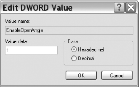
Once at the SheetMetal folder, create a new
DWORDentry named EnableOpenAngle.For the value data, set it to 1, as shown here.
There is a very close association between sheet-metal design and manufacturing, and the flat pattern solution within Inventor embraces this relationship. Inventor generically supports the ability to translate models to a variety of file formats, but Inventor sheet metal actually has its own utility to support the translation to .sat, .dwg, and .dxf formats. After selecting the Flat Pattern browser node, you can right-click and select Save Copy As; this launches the Flat Pattern Translation dialog box. For .sat files, a simple option defining the file version will be presented. For .dwg and .dxf file formats, an extensive list of options and file-processing capabilities are made available to you.
Within the Flat Pattern Translation dialog box, you will find standard options for file type, but there is also a Layer tab that supports layer naming and visibility control. The last tab is the Geometry tab, which allows you to decide whether you want to apply a variety of manufacturing-specific options to the translation. The first of these options is for spline simplification, because many CNC profile manufacturing centers cannot leverage splines and are restricted to arcs and lines.
This utility allows you to apply faceting rules to break the outer contour of flat patterns into linear segments. The second options group relates to the post-processing of the translated file, allowing you to force the 2D result into positive coordinate space and to merge interior and outer contours into polylines, which may be critical for a path-based tool. Sometimes you'll need additional tool path manufacturing information in your .dxf/.dwg output. For this, the flat pattern has the ability to export unconsumed sketches created on the flat pattern. Only visible sketches are exported, and a layer called IV_UNCONSUMED_SKETCHES was added to support the collection of these sketches.
iParts have traditionally not been very sheet-metal friendly, but several enhancements were added in Inventor 2009, making sheet-metal iParts incredibly flexible and powerful. True sheet-metal configurations and flat pattern support within member files represent the core of this new functionality.
In the "Using Sheet-Metal Templates and Rules" section earlier in this chapter, we discussed a number of advantages related to the move from templates to the style library. An additional advantage that we didn't discuss was that this evolution also makes sheet-metal rules and unfold rules consumable by iPart factories. In a nutshell, this means configurations of sheet-metal parts can be differentiated exclusively by referencing different rules. So, from the perspective of the folded model, identical fit and function designs can be made with completely different manufacturing processes reflected per member file.
For example, a bracket could be designed and configured in basic mild steel or optionally in an upgraded stainless steel version. Sheet-metal configurations via iParts could be very beneficial and profitable to a company that deals in varieties of components that need to fit into the same space but utilize different materials and/or manufacturing processes. On the other front, the folded model might be identical for all members, but a different sheet-metal unfold rule could be used to accommodate different manufacturing locations of your component.
With the addition of flat pattern edit features and named flat pattern orientations being added to the iPart definition (the new Sheet Metal tab within an iPart author table), full support for sheet-metal manufacturing configurations can also be realized in Inventor. There has been a great deal of discussion about Autodesk's digital prototyping strategy within the CAD/CAE community, but the enhancements in Inventor with regard to sheet-metal configurations and manufacturing configurations really deliver on the promise of this concept.
We alluded to the next significant enhancement to sheet-metal iParts in the discussion of flat pattern edit features: flat pattern models are now included within member files. In the past, a single flat pattern was computed for the iPart factory, and changing the active folded member simply forced the flat pattern to be recomputed. Although this might not sound so bad from the perspective of the factory, once a folded member file is generated to disk, this limitation becomes apparent.
Before Inventor 2009, factory member files did not contain a flat pattern model, only the factory did. When you created a drawing of an iPart factory flat pattern, you were actually documenting the active factory member's flat pattern. This meant you would need to defer updates of your drawing so that you could ensure that when editing you had the correct folded member selected so as to not change the result of the flat pattern view. Since Inventor 2009, both the folded and flat pattern models are generated to disk, allowing you to create flat pattern documentation referencing the member file flat pattern instead of the factory.
For sheet-metal designers who already have iPart factories with sheet-metal member files on disk, a number of provisions have been added to help get the additional flat pattern body out to the instantiated member files. The first thing to remember is that Inventor migration has changed over the years to have minimal impact on files; this has been done to reduce the performance impact of opening a legacy file or files in a newer version of Inventor. This also means that aspects such as getting the newly available flat pattern information into an existing file will not be automatic.
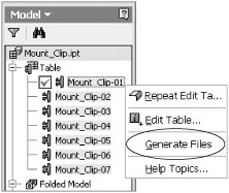
There are a number of scenarios in which it is fundamentally detrimental to have these updates automatically push out, most notably for a situation in which Vault, Product Steam, or other PDM system is utilized for data management. The iPart factory member nodes support a context menu entry called Generate Files, as shown in Figure 6.23. This tool is intended to support the batch creation of member files on disk; it can also be used to force updates, such as the flat pattern, out to the member files already in existence. In addition, you can use a pull method vs. a push method. If you open the iPart factory, execute the Rebuild All operation, and then save the rebuilt and migrated data, the member files when individually opened will see that they are out-of-date with the factory. Selecting the now-enabled Update button within the individual member file will then draw in the flat pattern information automatically.
Although the sheet-metal feature set is extensive, sometimes using non-sheet-metal features can be helpful or possibly even required to accomplish your design. The challenge when using non-sheet-metal features is to honor the guiding principles of sheet-metal design so that the resulting component can be unfolded; in addition, you want to incorporate sheet-metal conditions so that the features are manufacturable and therefore cost effective.
Although it's possible to design sheet-metal components using lofts, solid sweeps, and shells, these features can produce unpredictable and hard-to-control results. The Loft tool, unless highly restricted, produces doubly curved surfaces that cannot be unfolded properly. Although it's possible to utilize rails to control loft curvature, it's time-consuming and invariably frustrating. Solid sweeps are a measure better than lofts, but these too can create unintended doubly curved surfaces. The Shell tool can be used nine times out of ten to successfully create a legitimate sheet-metal feature, but the tenth time, if it doesn't work and it's not clear why, will be confounding. If you use the parameter Thickness to shell your component, you'll probably be in fairly good shape, but there are certain situations in which the Shell tool cannot assure uniform thickness after the shell. These situations are not always simple to predict.
By far, the most successful non-sheet-metal feature workflows typically leverage a surface that is later thickened. The reason that these workflows are so successful is that it's often easier to ensure that the resulting model embodies sheet-metal conditions (the side faces are perpendicular to the top and bottom faces) since the part can be thickened normal to the surface. When constructing surfaces that will be thickened, the Extrude and Revolve tools are excellent choices because they have restricted directions in which features are created, which can help ensure that only cones, cylinders, and planes are created (these can be unfolded). The Sweep tool is possibly another good choice, but care needs to be taken to ensure that the profile and the sweep path do not contain any splines or ellipses that might prevent unfolding. For each of three previously mentioned features, the sketch profile geometry should ideally be limited to arcs and lines to help ensure the creation of unfoldable geometry. Another common surface-generating workflow is to use Derived Component, where you select the Body As Work Surface option when placing the derived component into the sheet-metal file. This workflow can be combined well with either a thicken feature or a sheet-metal face feature after creating projected sketches for each planar surface.
One of the biggest benefits of working with surfaces is that you can apply complicated alterations to the surface prior to thickening. Some of the most common features utilized to create cutting surfaces are Extrude, Revolve, and Sweep. The Split tool (and perhaps Delete Face) can be utilized to remove faces from the thickened surface selection. When using the Sweep tool, the Guide Surface Sweep option is ideal because the swept profile is rotated along the path to ensure that it remains normal to the guide surface. Sometimes a thickened sheet-metal component needs to be trimmed with a complicated profile. For these situations, a swept surface combined with the sculpt feature can result in a model that still has sheet-metal conditions.
The Inventor sheet-metal environment has been designed to work with imported geometry, because its solid unfolder is concerned with topology, not with features. This means that imported parts can be brought into Inventor and unfolded as well as modified with additional features. To be successful working with imported sheet-metal models, you must follow a few general guidelines.
There are two main methods for importing parts into Inventor: the Open command and the Import tool that's on the Insert panel of the Manage tab. If you are able to use Open (which is preferred), a standard part template is going to be utilized by default to embed initial styles and document options, so the first step will be to use the Convert To Sheet Metal tool to draw the sheet-metal subtype options and rules into the document. If you use the Import tool from within an empty sheet-metal document, the imported geometry will be in the form of a surface. To work with this geometry, you will need to thicken each surface, which can be a time-consuming process. It is recommended, when possible, to "open" imported parts so that a solid body can be recovered.
The next step you need to accomplish is the measurement of the sheet thickness of your imported model; once you have this value, you can match it with an appropriate sheet-metal rule (or create a new one). Matching the thickness can be as simple as taking a measurement from the sheet and overriding the Thickness value within the Sheet Metal Defaults dialog box with a simple copy and paste. Since the solid unfolder works with evaluated topology to facilitate the unfolding, the thickness of the actual part must match the thickness of the active sheet-metal rule exactly.
If the imported part contains portions that are not of uniform thickness, proper unfolding may not be possible; spend some time evaluating your imported model to ensure that it conforms to sheet-metal conditions. If your imported model contains faces defined by splines or ellipses, you are not going to be able to unfold your part. In these cases, removing these faces and replacing them with faces defined by tangent arcs may be an acceptable modification.
On the Environments tab is the Convert To Sheet Metal tool. The purpose of this tool is to take a component that has been designed with a regular part template and convert that document to a sheet-metal subtyped document. This means all the sheet-metal reference parameters and the default sheet-metal rule and unfold rule are automatically added to the document.
You can also convert a sheet-metal part back to a part document. Basically this deletes the flat pattern and disables the sheet-metal functionality, but the sheet-metal parameters are not deleted.
The Drawing Manager environment contains several tools and functions specifically focused on helping you document your sheet-metal design. A quick overview of sheet-metal–specific tools might help you understand them a bit better.
The first step in creating your documentation will be to choose which model file to reference, but sheet metal has the added requirement of deciding between a folded model and a flat pattern view, as shown in Figure 6.24. Once a sheet-metal model file is selected on the Component tab, a Sheet Metal View options group will appear immediately below the file's path information. The displayed options allow you to choose between creating a folded or flat pattern view and, in the case of a flat pattern, choose whether you want center marks to be recovered for any embedded Punch tools. The default view options will change based on your selection, because the flat pattern has a clear distinction between its top (default) face and its bottom (backside) face. The actual orientation of the 3D flat pattern defines what is a top and what is a bottom face. This also impacts bend orientation with respect to what is reported as up and what is reported as down. All punch angular information is based on the virtual x-axis previewed during flat pattern orientation.
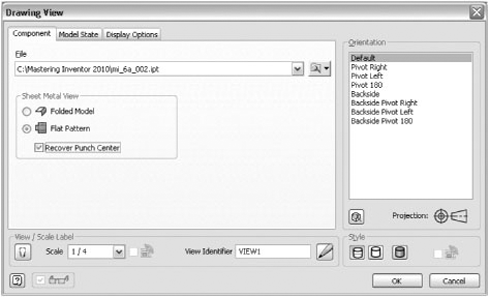
Figure 6.24. Drawing Manager: Drawing View dialog box's Component tab with options displayed for sheet-metal view creation
The Model State tab may also be of interest, because sheet-metal iPart members can be individually selected when a factory file is referenced, as shown in Figure 6.25. Choosing between a folded model and flat pattern is also necessary when creating a drawing view of the sheet-metal iPart member. If the member has not already been placed, selecting the member from the Drawing View dialog box will automatically create the file.
The last tab is the Display Options tab, which is important because it controls whether sheet-metal bend extents should be drawn in the view as well as controls other annotations such as work features and tangent edges, as shown in Figure 6.26.
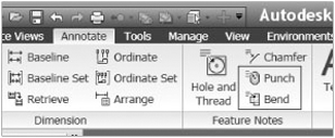
Once you've created the view of your sheet-metal component, you can switch to the drawing Annotate tab to complete the documentation of your design. The sheet-metal annotation tools within the Drawing Manager are specific to flat pattern views. You can add bend notes and punch notes, as shown in Figure 6.27. Bend notes allow you to recover bend angle, bend direction, bend radius, and K-factor (not on by default) for any bend centerline. The punch note allows you to select a formed punch, center mark, or 2D alternate punch representation in order to recover the punch angle, punch direction, punch ID, and punch depth (punch ID and depth need to be added to the Punch tool description when authored). When editing the punch note, you will also see a Quantity command that allows you to recover the number of instances of the same Punch tool in the view.
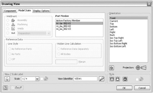
Figure 6.25. Drawing Manager: Drawing View dialog box's Model State tab with options displayed for sheet-metal iPart member view creation
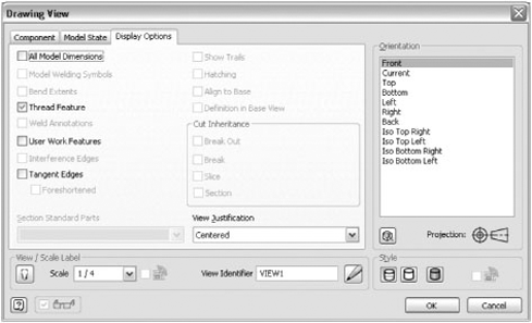
Figure 6.26. Drawing Manager: Drawing View dialog box's Display Options tab with options displayed for sheet-metal bend extents
You can utilize the General Table tool to create a Drawing Manager bend table (not to be confused with bend tables utilized for unfolding) that documents all the bends in a selected view. To create a bend table, follow these steps:
Select General from the Table panel of the Drawing Annotation tab.
Select an existing flat pattern view.
Decide whether the chosen columns are acceptable (bend direction, angle, and so on); if not, alter the selected columns.
Choose the Bend ID format, and enter a prefix if desired.
Click OK to create the bend table.
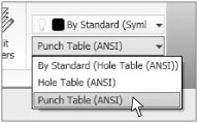
Punch table creation is a little different, because it has been incorporated within the preexisting Hole Table annotation tools. The reason that punch support was combined with hole tables is that you most likely used the Hole tool out of convenience, not necessarily to convey a manufacturing process. To make sure all of this tool-based information is consolidated together, an enhancement to hole tables was made. After invoking the Hole Table – View tool and selecting a flat pattern view, you will see that the standards in the toolbar have changed to reflect predefined hole table standards. Within this list (as shown in Figure 6.28) is an example standard for punch tables, which prevents you from having to first create a standard hole table and then editing it to add all the punch information columns.
From within the Text tool, you can reference the sheet-metal flat pattern extent values by selecting a new Sheet Metal Properties option from the Type list, as shown in Figure 6.29. Once you've selected the Sheet Metal Properties type, the Property list will provide options for entering the flat pattern extents area, length, or width in the text box.
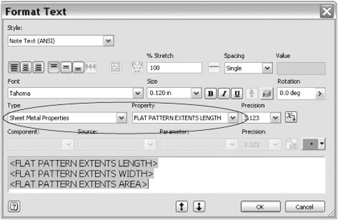
Figure 6.29. Drawing Manager Format Text dialog box displaying Sheet Metal Properties option for flat pattern extents
The last annotation tool that can interact with sheet-metal properties is the Parts List tool. To recover flat pattern length and width extents within the parts list, follow these steps:
From within your sheet-metal model, right-click on the file name node in the Model browser and choose iProperties.
Select the Custom tab and create a new custom iProperty named Length.
Ensure the type is set to Text.
Enter a value of = <FLAT PATTERN LENGTH> cm.
Repeat steps 2–4 for a custom iProperty named Width, entering a value of = <FLAT PATTERN WIDTH> cm.
Save the sheet-metal model file.
From within the Drawing Manager, launch the Parts List tool.
Using the Select View tool, select a flat pattern view of the sheet-metal model containing the custom iProperties, click OK, and place the parts list on your drawing.
Right-click your parts list, and select the Edit Parts List tool.
Right-click the table, and select Column Chooser.
Repeat step 11, creating an additional property named Width.
Once complete, click OK.
Select the new column named Length, right-click, and select the Format Column tool.
Change the formatting and precision of the length to match your needs.
Repeat step 15 for the Width column, clicking OK when complete.
During the discussion concerning the move from a template-based style environment to a style library, you may have been wondering how to actually go about making the switch. Luckily, some tools ship with Inventor that can help extract your previously defined sheet-metal style information. To determine whether these tools can work for you, the following sections detail some challenges that you might run into while harvesting your styles as well as some information pertaining to the tools that can help you through the process.
One aspect of legacy sheet-metal styles that has no precedence in the style library relates to parameter indirection. In versions of Inventor previous to 2009, sheet-metal users were able to build sheet-metal styles that were driven by referenced parameters that in turn referenced externalized data sources (in other words, an Excel file). Within the XML-based style library, there is no way to ensure that the externalized file containing the parameter information will be found, so parameter indirection has never been supported.
However, numerous sheet-metal designers use this capability quite successfully to construct sheet-metal configurators. With this in mind, Inventor continues to support the use of linked parameters within the sheet-metal rule definition; it simply doesn't allow sheet-metal rules containing parameter indirection to be published to the style XML library. Since sheet-metal rules exist as document-level objects as well as published style XML entries, there's no reason you can't use externalized parameters with the sheet-metal template.
The Hidden Tools of Harvesting
When discussing the sheet-metal transition to the style library, a common question is often asked: what happens to my data? The good news is that Inventor can preserve and migrate all the sheet-metal style information that is stored in each sheet-metal document, whether the style is active or not.
Once users see that the data is still all there, the next question generally is this: how do I move my sheet-metal template styles to the style library? As a means to sort through and publish your sheet-metal styles as sheet-metal rules, two additional tools have been provided: the Style Library Manager and the Style Management Wizard. These utilities work in conjunction with Inventor and are fundamentally intended to support the process of making the big change away from templates and toward the style library. This also means these tools are typically used infrequently since it's not every day that new style information is made ready for consumption in the style library. With this in mind, we'll walk through these tools to ensure that you understand how to successfully publish your data.
The Style Management Wizard, also known as the harvester, allows you to select specific target files that contain style information and either purge that style information or publish it to style library XMLs. Although the harvester supports that capability to search all the files in a given project, most sheet-metal customers use a single template that contains every bit of sheet-metal style information they've ever thought of. This consolidation of information is one of the main problems that influenced the move away from templates and toward the style library, because most customer sheet-metal files are packed with style information that has never and will never be used.
The harvester also allows individual files to be added, regardless of the project location in which they reside. For the majority of sheet-metal customers, a single targeted file might contain all the style data you want to harvest and publish into the sheet-metal rule style XML file. The harvester then needs to know what to do with the extracted information. You can either create a new style library destination or select an existing style library (for example, your Inventor design data folder), but be cautious because this will overwrite any styles or rules that have an identical name.
This is in fact an important aspect of the Style Management Wizard—the last imported style definition for a given style name wins. Once you initiate the harvesting of style information, you will have to wait about five minutes because Windows, Inventor, and the harvester all have to work through some processes; don't exit—it will succeed...just give it some time. When the harvesting is finished, you will see a log entry that reflects that the target file was successfully harvested.
To successfully accomplish the harvesting of your sheet-metal style information, you will need to complete a few preparation tasks. First, the file or files that you intend to extract styles information from must be migrated to the current version of Inventor. The next step is that you should ensure the project file containing the referenced file(s) has its Use Style Library option set to Yes. Lastly, ensure that the location you will be writing style information to is not read-only. It is not uncommon for the Design Data folder (the default location is C:Program FilesAutodeskInventor 2010) to be set to read-only; if you're going to edit the styles in this location, you might want to verify that they're editable. If you want to harvest the style information from a specific file, follow these steps:
Launch the Style Management Wizard from the following location: Start
Once you arrive at the welcome screen, click Next.
Select a project file location that contains a file that you want to harvest sheet-metal style information from, and then click Next.
Select the folder icon in the upper-left corner in order to add a specific file to the harvesting queue.
Once selected, you will see the filename and file path in the harvest queue; click Next.
The next page allows you to select between harvesting and purging styles information; we will use the default option, which is Harvest Styles Into A Target Style Library.
Next you must choose whether you want to create a new style library based on your target file or edit an existing style library. For this example, we will edit the Inventor 2010 Design Data library, but you may want to create a new library to verify the results. Click Next.
The last step is to click Start to begin the process of extracting your sheet-metal style information.
When the harvesting log says it has finished and the Pause button changes to Finished, you have completed the harvesting process.
The Style Library Manager is a utility that allows you to manipulate styles that have already been published to a style XML file. Different from the Style Management Wizard, the Style Library Manager allows you to copy, rename, and delete styles. For the purposes of sheet-metal library management, you'll likely use the Delete function the most. An important key to remember when working with the Styles And Standard Editor dialog box is that style information can be added to the library only from within Inventor; there is no support within Inventor to delete items from the style XML files.
Although there is a tool named Purge Style within the right-click menu of a style (as shown in Figure 6.30), all of these tools are from the perspective of the document-level version of the style, the cached style. Update Style, for example, overwrites the cached style information with whatever is in the style file. If the style existed only in the cache, Update Style would never become enabled. The only entry in the Style right-click menu that adds information to the style XML file is Save To Style Library. For any editing of the style XML that requires renaming or deleting, you will need to utilize the Style Library Manager. To access the Style Library Manager, select Start
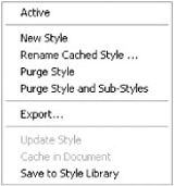
- Take advantage of the specific sheet-metal features available in Inventor
Knowing what features are available to help realize your design can make more efficient and productive use of your time.
- Master It
Of the sheet-metal features discussed, how many require a sketch to produce their result?
- Understand sheet-metal templates and rules
Templates can help get your design started on the right path, and sheet-metal rules and associated styles allow you to drive powerful and intelligent manufacturing variations into your design; combining the two can be very productive as long as you understand some basic principles.
- Master It
Name two methods that can be used to publish a sheet-metal rule from a sheet-metal part file to the style library.
- Author and insert punch tooling
Creating and managing Punch tools can streamline your design process and standardize tooling in your manufacturing environment.
- Master It
Name two methods that can be utilized to produce irregular (nonsymmetric) patterns of punch features.
- Utilize the flat pattern information and options
The sheet-metal folded model captures your manufacturing intent during the design process; understanding how to leverage this information and customize it for your needs can make you extremely productive.
- Master It
How can you change the reported angle of all your Punch tools by 90 degrees?
- Understand the nuances of sheet-metal iPart factories
Sheet-metal iPart factories enable you to create true manufacturing configurations with the inclusion of folded and flat pattern models in each member file.
- Master It
If you created sheet-metal iPart factories prior to Inventor 2009, any instantiated files contain only a folded model. Name two methods that you could use to drive the flat pattern model into the instantiated file.
- Model sheet-metal components with non-sheet-metal features
Inventor doesn't always allow you to restrict yourself to sheet-specific design tools; understanding how to utilize non-sheet-metal features will ensure that your creativity is limitless.
- Master It
Name two non-sheet-metal features that can lead to unfolding problems if used to create your design.
- Work with imported sheet-metal parts
Understanding the way in which Inventor accomplishes unfolding as well as how to associate an appropriate sheet-metal rule are keys to successfully working with imported parts.
- Master It
Name the one measured value that is critical if you want to unfold an imported part.
- Understand the tools available to annotate your sheet-metal design
Designing your component is essential, but it's equally important to understand the tools that are available to efficiently document your design and extract your embedded manufacturing intent.
- Harvest your legacy sheet-metal styles into sheet-metal rules
Using the harvesting utilities provided, you can extract your legacy sheet-metal styles and publish them into style library sheet-metal rules, pre-associated to material styles, sheet thickness values, and sheet-metal unfold rules.
- Master It
How can you extract sheet-metal style information from a legacy part files or template files for the purpose of publishing it with a Sheet Metal Rule?