
The ability to reuse parts and features in other designs is an important step to increasing productivity. Inventor provides this ability through several different workflows. This chapter introduces you to several methods that will assist you in achieving your goal.
Developing the proper workflow for your company will depend on several criteria. Depending on your involvement with the functional design aspect of Inventor, you may be converting some iParts to Content Center components. Additionally, you may decide to utilize iParts and iFeatures for design development if your design needs require them.
In this chapter, you'll learn to:
Create and modify iParts
Create and use iFeatures and punches
Copy and clone features
Link parameters between two files
Configure, create, and access Content Center parts
iParts differ from standard parts in that they are essentially table-driven part factories, allowing for many different variations to be generated from the same basic design. When an iPart is inserted into an assembly, a dialog box appears and allows you to specify a variation of the original part from the table.
Within the iPart factory, you can configure feature sizes by specifying different values for the same parametric dimension, you can choose to include or suppress entire features, and you can configure the iProperties of a part. In addition to these general configuration controls, you can configure thread features and work features such as work planes, axes, and points. There are two basic forms of iParts: table-driven and custom. Both types can be combined to create a table-driven part that allows custom input.
Each original iPart, often called a factory part, generates individual derived, noneditable member parts. Member parts placed within an assembly can be substituted with a different member of the factory. When a member part is replaced, generally all existing assembly constraints will be retained.
iParts bring several advantages within assemblies. They essentially function as completely different parts, allowing dimensional changes, feature suppression, transfer of iProperties, and other values.
iParts are created from an existing part. Existing parts already contain features and parameters. Although you can modify a standard part by changing the parameter values, this will affect the part wherever it is used. To create configurations of a standard part, you must first convert the part into an iPart.
You can publish iParts to a custom content folder for use as Content Center components or as additional content for functional design such as Frame Generator and Bolted Connections. Published iParts can also be used in other aspects of functional design where allowed.
Before converting a standard part into an iPart, you should first modify the parameter list and rename the parameters to something more meaningful than the default names, such as renaming d1 to Length. To explore these tools, follow these steps:
On the Get Started tab, click the Open button.
Browse for the file named
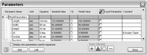
mi_7a_001.iptlocated in the Chapter 7 directory of the Mastering Inventor 2010 folder, and click Open.Click the Parameters button on the Manage tab.
The Parameters dialog box opens, and you'll note that many of the parameters have been named already. Name the unnamed parameters d0, d1, and d2 to Length, Width, and Height, as shown in Figure 7.1, and then click Done to exit the Parameters dialog box.
After you've modified the parameter list, you then create the iPart table, configure it to include columns of features you want to modify, and add rows for each new configuration of the part you want to create.
On the Author panel of the Manage tab, click the Create iPart button. All the named parameters will automatically show up in the iPart table.
To remove columns that you do not want to include in the table, click the parameter in the right pane, and use the << button. You can also select columns headers in the table and then right-click and choose Delete Column. Remove all the columns except Length, Width, and Height.
Add a row to the table so that you can create a variation of this part. Right-click anywhere in row 1, and choose Insert Row.
Set Height to 40mm, and leave the other values as they are.
Create additional rows until you have eight rows with the Length, Width, and Height values as shown here:
Length
Width
Height
100mm
50mm
20mm
100mm
50mm
40mm
100mm
75mm
20mm
100mm
75mm
40mm
200mm
50mm
20mm
200mm
50mm
40mm
200mm
75mm
20mm
200mm
75mm
40mm
Once your table is complete, click OK.
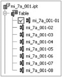
Find the Table node in the browser, and click the + sign to expand the node. You will see each member (variation) of the iPart table listed, as shown in Figure 7.2.
You can switch between each member of the iPart by double-clicking it or by right-clicking it and choosing Activate. Making changes to the features or sketches will change the active member but will not automatically update the table. If you make a change and then go to set another member active, you will be prompted to save the changes to the table or discard those changes. This is because the default edit mode is set to edit the entire iPart factory rather than the members individually. Changes made in the table will be carried through to the members either way. You'll learn more about adjusting the edit scope in the "Working with Sheet-Metal iParts" and "Changing Color in iParts" sections.
To edit an iPart, you can double-click the Table node in the Model browser, or you can right-click and choose Edit Table. You can also right-click and choose Edit Via Spreadsheet to edit the table with Microsoft Excel. Although some iPart table-editing tasks can be done in both Inventor and Excel, others should be done only in Inventor. Follow these steps to explore the process of editing an iPart table:
On the Get Started tab, click the Open button.
Browse for the file named
mi_7a_003.iptlocated in the Chapter 7 directory of the Mastering Inventor 2010 folder, and click Open.Right-click the table in the browser, and choose Edit Table.
In the iPart Author dialog box, right-click the Length column header, and choose Key. Then click the arrow and select 1 to designate that this is the first parameter by which this part should be specified.
Set the width to be key 2 and the height to be key 3; then click OK to close the iPart Author dialog box.
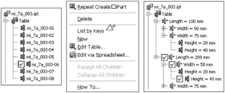
Right-click the table in the browser, and choose List By Keys. This sets the members to be listed by parameter keys in descending order, creating a drill-down tree so that you can select the length, then the width, and then the thickness, as shown in Figure 7.3. Note that the active member is designated by a check mark next to the appropriate key.
Next, right-click the table in the browser, and choose Edit Table again.
Click the Properties tab to see the list of iProperties that are available for this part.
Locate the Project category in the left pane, and expand it to reveal the Description property.
Select Descriptions, and use the >> button to include it in the iPart table.
Confirm that the Description column shows as a column in the table, and then click OK.
Right-click the table in the browser and choose Edit Table via Spreadsheet to open the table in Microsoft Excel.
Select cells F2 through F9, and then right-click and choose Format cells.
Set the cells to General, and click OK. This is necessary to allow Excel to evaluate the expression you will build in the next step.
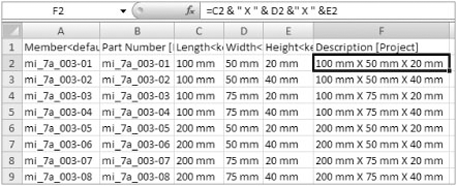
In cell F2, enter = C2 & " X " & D2 & " X " & E2.
Right-click cell F2, and choose Copy.
Then select cells F3 through F9, and right-click and select Paste. Figure 7.4 shows the Excel table complete.
Save the spreadsheet and close Excel.
Because your table now contains data that is not in the part file, you will be prompted to update the file. Click Yes in the message dialog box.
Right-click the table in the browser, and choose Edit Table.
In the iPart Author dialog box, notice that the cells in the Description column are highlighted to inform you that there is a formula in those cells.
Click OK to exit the iPart Author dialog box.
A common use of iParts is to create a configuration of a part family that might include features in some cases and not include them in others. You can add a column to the table to control feature suppression. To do this, follow these steps:
On the Get Started tab, click the Open button.
Browse for the file named
mi_7a_005.iptlocated in the Chapter 7 directory of the Mastering Inventor 2010 folder, and click Open.Right-click the table in the browser, and choose Edit Table.
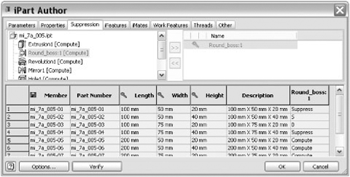
In the iPart Author dialog box, click the Suppression tab.
Select the feature called Round_Boss1, and click the >> button to add it as a column in the table.
Enter suppress for the all the 100mm length rows.
Click the Verify button to ensure that you haven't entered a value that will not work, such as entering a spelling error. Errant cells will highlight in yellow, and you should fix them.
Click OK to return to the model.
Use the browser tree to activate different members, and notice that the boss features will be suppressed for all the 100mm members. Figure 7.5 shows the iPart Author dialog box.
You'll notice that by suppressing the boss feature, both instances of the boss are suppressed. This is because the boss was mirrored. To suppress just one boss, you could suppress the mirror feature; however, doing so would suppress one of the revolved features as well, because it was included in the mirror. Keep this in mind when creating left and right configurations of the same part. Oftentimes you will need to create separate features so that they can be controlled independently.
You can use the Work Features tab to indicate whether each work feature is included or excluded individually. A common use for this would be to create several work features in an iPart and then include only the one that is to be used for mating the specific iPart member in the assembly environment so as to control a specific offset value.
You can change the thread parameters of a tapped hole or external thread feature for each member of the iPart table independently. Just use the Thread tab to include any thread parameters, which will vary. You should include all parameters that will vary between any of the table members; otherwise, the hole/thread feature may generate errors when switching between members. Oftentimes these errors may not become apparent until you attempt to publish your iPart to Content Center.
An example of this would be if you neglected to add the Class parameter to the table, even though not all of the members in the table have the same thread class. The thread class would then be set to the original thread class and would not get changed when the iPart is switched to a thread that does not include the original thread class. The same would be true of course if the Class column was included but wasn't changed.
You can specify the sheet-metal rule, the sheet-metal unfold, and a named flat pattern orientation for individual members in an iPart. To edit the bend order, you must edit the member scope as opposed to making the edits per the iPart factory. Once the iPart is set to Member Scope, bend order changes in the flat pattern are set to the active member. To do this, you need to first enable the iPart/iAssembly toolbar:
Go to the Tools tab, and click Customize on the Options panel.
In the Customize dialog box, select the Toolbars tab, and select the iPart/iAssembly toolbar from the list.
Click the Show button to turn the toolbar on.
Click Close, and then click and drag the toolbar to the desired position.
Click the drop-down, and click the Member Scope button, as shown in Figure 7.6

Once the scope is set to edit just members, you simply set the member you want to edit to be active and then make the bend order changes needed.
To set iPart members to be different colors, you can create a custom iPart parameter on the Other tab and set it to the Display Style Column option. Then you can edit each member row of the iPart to be a different color. It is important that the name matches exactly, however, so be careful to match case. This means that entering red for Red will cause a mismatch. To avoid this, it is recommended that you use the Member Scope edit mode, as described in the previous section, to make color style edits to the part. This way, you can just set the member active, change its color, and have the color change recorded in the iPart table automatically. To set up a color column, follow these steps:
On the Get Started tab, click the Open button.
Browse for the file named
mi_7a_012.iptlocated in the Chapter 7 directory of the Mastering Inventor 2010 folder, and click Open.Right-click the table in the browser, and choose Edit Table.
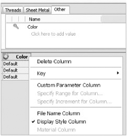
In the iPart Author dialog box, click the Other tab.
On the Other tab, click the Click Here To Add Value line.
Type Color for the value name.
Right-click the column header, and choose Display Style Column, as shown in Figure 7.7.
Type Default into the Color column for each of the three rows. Then click OK to exit the iPart Author dialog box.
Ensure the iParts/iAssembly toolbar is active. To do this, follow these steps:
Go to the Tools tab, and click Customize.
Click the Toolbars tab.
Select the iPart/iAssembly toolbar from the list.
Click the Show button.
Click the Close button.
Click the drop-down, and click the Member Scope button.
From the Quick Access bar (located at the top of the screen), select the color style drop-down, and choose Blue.
Expand the iPart table, use the keys to set the 25mm × 50mm member active, and then set its color to Red.
Change the edit scope to Edit Factory Scope using the iParts/iAssembly toolbar.
Use the keys to set the 50mm × 50mm member active, and then set its color to Green.
Right-click the table in the browser, and choose Edit Table. You will receive a message asking whether you would like to set the table to match the document (that is, the part). This demonstrates that when you are making edits to the model with the edit scope set to Factory, the changes to members do not get written back to the table automatically. Using the Member Scope edit option is therefore recommended. You also get this message if you change the active member because the table is verified every time you switch members.
Click Yes, and then take a look at the Color column to ensure that the colors match what you have set them to.
The Options button located in the lower-left corner of the authoring dialog box allows you to create and edit part numbers and member names for iParts. You will typically want to set these naming options before you begin adding rows to the iPart table so that as rows are added, they are automatically named according to these options.
Notice the disk symbol located in the Member column header in Figure 7.8. This indicates that the Member column will be used as the filename for each iPart member. If you prefer to have the Part Number column used for the filenames, you can right-click that column header and select File Name Column.
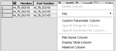
A Member Name value is automatically created for each member as rows are added based on the settings for part number and member name options. You can override these by editing the table in Excel, and you can even use a formula to create the names based on a concatenation of other column values in the table.
Once your iPart table is complete, you may want to generate the parts from the table. You can do this so that the parts are established ahead of time, or you can allow the files to be generated automatically as they are used. If you have an iPart table with two dozen rows, it might make sense to generate them ahead of time. However, if you have an iPart table of 200 member rows, then it might make sense to allow parts to be generated only when that particular size is used. To generate member part files, right-click the table, and choose Generate Members. Each member in the row will be created as a derived part based on the table values. Because these parts are often used over and over in many assemblies, it is often recommended that they be stored in a library folder. Recall that folders designated as libraries in your project file are handled as read-only by Inventor.
The library directory where you want to save the iPart members is set up by you, and it is required that you use the same name as the factory library but preceded with an underscore. As an example, if you place the iPart factory file in a library folder named Fasteners, Inventor will automatically place all iPart members generated from that factory part in a second library folder named _Fasteners.
However, you are not required to store iParts in libraries. If you do not use libraries and you place an iPart member into an assembly or use the Generate Members option, Inventor will create a folder of the same name, and at the same level as the iPart factory, and store the iPart members there. For example, if you have an iPart factory file named ClipBracket.ipj saved at C:Mastering Inventor, then when ClipBracket.ipt is used in an assembly, a subdirectory called ClipBracket is created (C:Mastering InventorClipBracket), and the iPart member file is created there. Custom iPart members are always stored in a location specified by the user.
A custom iPart is an iPart factory that has one or more columns designated as a custom parameter column. A custom parameter column allows input of any value and, in turn, generates a custom iPart with infinite variations. Custom iParts are valuable for creating tube and pipe lengths, structural steel members, and other parts that require unique size input at the time of insertion.
To designate a column as a custom parameter column, simply right-click the column, and select Custom Parameter Column. Columns that are set as keys are not permitted to be custom columns. Rather than setting an entire column to be custom, you may want to set just the column entry for a single member to be custom. To do this, you can right-click any cell in a nonkey column and choose Custom Parameter Cell. After that, you can right-click and set both columns and cells to restrict input to a specified range and increment.
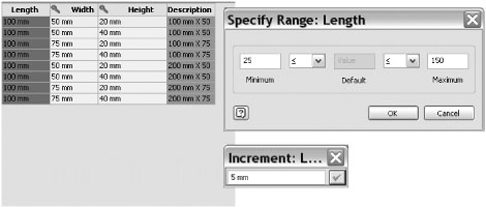
Here is a common example of setting a range for a fastener part:
You set the Length column to be custom.
You set the range so the fastener can be placed only in lengths from 25mm to 150mm, as shown in Figure 7.9.
You set the increment to 5mm so that the lengths are limited to standard sizes.
When you place the custom iPart into an assembly, you specify the increments.
Unlike standard iParts, you save custom iParts to a location of your choice at the time of placement.
Before placing a completed iPart into production for others to use, test the accuracy and interface of your part by inserting the iPart using Place Component within a blank assembly file. Using Place Component, insert every member in the table, and inspect and/or measure the placed component.
Moving the test forward, create an IDW file with a base view of your assembly. You will also need to generate a parts list with the desired columns and verify the accuracy of each cell. Once you are assured of having accurate member components, you can then place this iPart into a project library folder. If you will be using this iPart in conjunction with the functional design features of Inventor, you will need to publish the factory iPart to a custom Content Center library.
Editing an original iPart factory follows the same workflow as creating an iPart. If you've placed the original iPart factory into a project library folder, then within that same project, it will not be able to be edited. Instead, create a new project file for the purpose of editing library parts. When creating a new project file, define the workspace for the project file by locating the project file in the main libraries subfolder. Any subfolder within the library path will now be editable with this specific project file.
With the new Library Edit project file active, open the iPart you want to edit. Locate the table in the Model browser, and either double-click or right-click to activate the iPart Author dialog box. At this point, you can edit any part of the table. When you have completed your editing, you can save the part to its original location.
You can convert an iPart factory component into a standard parametric part by deleting the table attached to the iPart. Simply right-click the table in the Model browser, and select Delete. The part will revert to a parametric part with no history of the iPart functionality in the part.
Using an iPart in an assembly design is a little bit different from creating parts within an assembly. With standard parts, you can edit any feature by activating the part. An iPart member or child cannot be edited since it is a derived component created by the factory or parent part.
To change between iPart members, follow these steps:
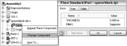
Locate and expand the iPart in the assembly browser tree.
Right-click the table.
Choose Change Component.
This opens the iPart placement dialog box, which allows you to specify a new member to be used in place of the existing one. Figure 7.10 shows the specific selection path for changing the component. This replacement procedure will replace only the selected component instance.
If you want to replace all exact duplicate members of the iPart within this assembly, follow these steps:
Right-click the part within the graphics window or the Model browser.
Select Component.
Choose Replace All. A dialog box will appear allowing you to select the same iPart factory.
Once the original iPart factory is selected, you will be prompted with the iPart placement dialog box to allow you to select the specific member to be used as the replacement.
When a component is replaced with a different member of the same family, as with iParts, normally all assembly constraints will be retained. If the replaced component is of a different family, then the assembly constraints might be broken. The same is true of parts in the same family if the original part used a certain feature to constrain to and the replacement part has that feature suppressed.
iFeatures are features that have been extracted from an existing part file and configured for reuse in other parts. If you are familiar with AutoCAD, you might relate iFeatures to blocks, in that you can write out blocks for reuse in other drawings. Any feature based upon a sketch can be used as an iFeature. Once extracted, the iFeature is stored in a catalog and can be placed into any other part file. Inventor is supplied with a number of standard iFeature parts. iFeatures cannot currently be published to Content Center.
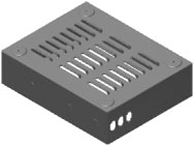
Using iFeatures in your designs can greatly simplify your workflow and accelerate productivity, especially if your designs contain repetitive features. Figure 7.11 shows an example of a sheet-metal part that could be created in less than 10 minutes using iFeatures.
iFeatures support sheet-metal features as well as normal part features. iFeatures are stored in the Catalog subfolder of the Inventor program in four subfolders. You can create additional subfolders as required. iFeatures are also available online from such locations as http://cbliss.com, www.sdotson.com, and others.
The following are some tips for working with iFeatures:
Keep your iFeatures clean, and do not include projected geometry or reference geometry unless required.
If dependent geometry is required, have it dependent only on geometry within the iFeature.
You should avoid the use of origin work planes, axes, and the origin center point for work features.
Use parallel and perpendicular constraints to other geometry in the iFeature, rather than horizontal and vertical constraints.
Know that updates to table-driven iFeatures do not update existing instances of the iFeature.
Save iFeatures before placing in other parts.
Once you have a part that consists of a feature or features that you want to reuse during the design of other parts, you can easily extract those features and place them into the catalog. The chief advantage of using iFeatures is that the original part does not need to be open in order to copy the feature. In addition, you can alter any of the parameters at will when inserting the feature into a new part.
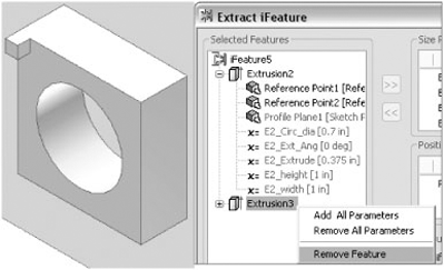
To reuse a part feature, select the Extract iFeature option on the Tools drop-down menu. Select the feature to be reused from the Model browser or the graphics window. If additional features exist that are dependent upon the selected feature, they will be added to the iFeature as well but can be deleted during iFeature creation if not needed. Figure 7.12 illustrates how to remove a dependent feature while creating an iFeature.
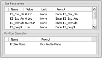
A standard iFeature similar to this will require a profile plane only in order to position the geometry onto a new part. In this example, you will notice that the named parameters and values are transferred from the existing part into the new iFeature. In Figure 7.13, you will notice that prompts will be added for each of the named parameters. When inserting this iFeature into a different part, you will be prompted to enter new values for these parameters if desired.
To place an iFeature in a standard part (not sheet metal), you simply browse to the stored iFeature and then select the face you want to use for placement. During the placement, you can adjust the rotation angle and size parameters. To see a simple example of how iFeatures are extracted and placed, follow these steps:
On the Get Started tab, click the Open button.
Browse for the file named
mi_7a_017.iptlocated in the Chapter 7 directory of the Mastering Inventor 2010 folder, and click Open.On the Manage tab, click the Extract iFeature button.
In the Model browser, click Extrusion2 as the selected feature, and the dialog box will be populated with the parameter information found in that feature.
Click the parameter named E2_Ext_Ang, and use the << button to remove it from the parameter list.
For this example, accept the default for the rest of the parameters, and click Save.
Notice that Inventor takes you straight to the
Catalogfolder. This location is specified in the Application Options dialog box and can be changed if needed. Choose a location underCatalogor create your own subdirectory, and name this iFeatureSquareSocket.ide. If warned about saving outside of the project path, click Yes.Place the iFeature back into the model as a test. On the Manage tab, select the Insert iFeature tool.
Click the Browse button to go to the
Catalogfolder automatically.Locate the SquareSocket feature you just created, and click Open.
Select the top face of Extrusion1 to use as the profile plane.
Once the plane is selected, set the angle to 45 degrees, use the flip arrow to ensure that the feature placed in the correct direction, and then click Next.
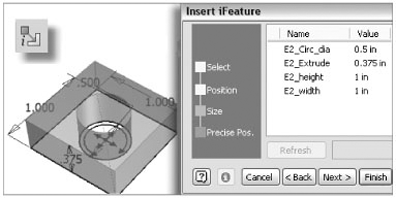
Enter 0.5 for the E2_Circ_Dia parameter and then click the Refresh button to see the diameter of the feature adjust. Once the size parameter has been adjusted, as shown in Figure 7.14, click Next.
You will be presented with two options for placing the iFeature; choose Activate Sketch Edit Immediately, and click Finish.
You will see that the iFeature sketch is set and ready to be edited.
Finish the sketch, and close the file.
Once iFeature files (.ide) have been extracted and tested, you can open them in Inventor and edit them much like iParts. Follow these steps to explore the options involved in editing an iFeature:
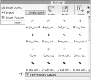
On the Manage tab, click the Place iFeature drop-down, and click the View iFeature Catalog button, as shown in Figure 7.15. This will take you directly to the Catalog folder in the Inventor program files where all iFeatures are stored.
Locate and open the file named
SquareSocket.idethat you created in the previous exercise. If you did not complete that exercise, you can open the file namedmi_7a_025.idefrom the Chapter 7 directory of the Mastering Inventor 2010 folder.
Use the Edit iFeature icon to refine parameter names, sizes, and instructional prompts for the placement of iFeatures. If the iFeature has dependent features, you can edit them as well. You can also rename the iFeature if you want to configure it in a more in-depth manner by using the iFeature Author Table dialog box.
The iFeature Author Table dialog box allows a table to be added to the iFeature so that rows and columns can be added to configure the iFeature in the same way that you configured a part file using the iPart Author dialog box. Once you've added the table to the iFeature, you can further edit it by clicking the Edit Using Spread Sheet icon to open the table in Microsoft Excel.
When creating iFeatures, it is usually a good idea to keep the original IPT file that you used to create the IDE file. This is often useful in case you want to totally redesign the iFeature or make a similar iFeature.
Including Placement Instructions
You can embed an instructional document detailing the placement selection requirements for more complex shapes that require faces to be selected in a certain order or need more information about size and settings. Here are the steps for including placement instructions:
On the Tools tab, click Insert Object.
Select Create From File, browse for the precreated instruction file, and then click OK.
The file will show in the 3rd Party browser node, as shown here.

Right-click the embedded object and select Placement Help to allow this file to be accessed from the feature dialog box during placement.
Punch features are really just iFeatures with extended functions that behave slightly differently than standard iFeatures. Punch features require a single sketch center point during iFeature creation. The sketch center point will be used to locate the punch feature upon insertion. The destination part will require an active sketch containing sketch center points for the location of the punch feature.
When creating a punch feature, consider that in normal use most features extend through the thickness of the sheet metal. Therefore, it is important to use the Thickness parameter when creating the iFeature. Constructed properly, the punch feature will adjust to the thickness of any sheet-metal part to which it is applied.
The part used in the following steps is a simple sheet-metal part with one cut feature. Figure 7.16 shows the sketch underlying the cut feature. The sketch was created utilizing a single center point, which will be used for placement when inserting the punch feature. There was no need to anchor the sketch, since it was created for the sole purpose of extracting a punch iFeature.
On the Get Started tab, click the Open button.
Browse for the file named
mi_7a_027.iptlocated in the Chapter 7 directory of the Mastering Inventor 2010 folder, and click Open.On the Manage tab, select the Extract iFeature tool.
Select Cut1 in the Model browser.
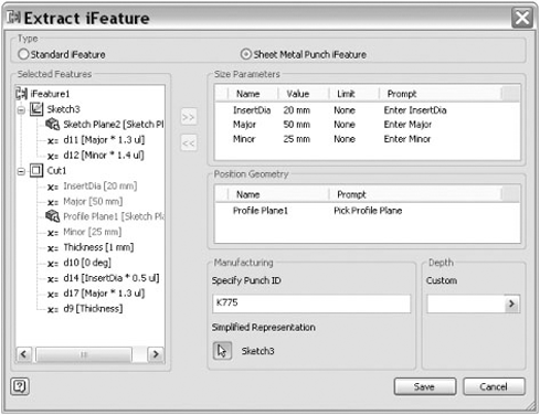
Click the radio button at the top of the dialog box to toggle the iFeature type to Sheet Metal Punch Feature.
Under the Manufacturing area, specify the punch ID as K775. Although not required, if it's included, this punch ID can be retrieved and placed onto a drawing in the form of a punch note or punch table so the shop floor will know which punch to use.
Click the Select Sketch button for Simplified Representation, and then click Sketch3 in the Model browser. Simplified sketches are optional but may help represent complex sketches more cleanly in the detail drawing.
When your dialog box resembles Figure 7.17, click Save, and select the
Punchesfolder in theCatalogdirectory.Name the punch feature
K775.ide. If warned about saving outside the project path, click Yes.
When working on a sheet-metal part, you can access iFeatures through the Punch tool or the Insert iFeature options in the Sheet Metal Features tool panel. The Punch tool is optimized for sheet-metal parts, so unless you are placing a regular iFeature, you should always use the Punch tool. Prior to placing a feature, you must have an unconsumed, visible sketch containing one or more center points from which the punch will position itself. Follow these steps to place a sheet-metal punch:
On the Get Started tab, click the Open button.
Browse for the file named
mi_7a_029.iptlocated in the Chapter 7 directory of the Mastering Inventor 2010 folder, and click Open.Sketch3 has been prepared for you so that you can use it to place your new punch.
Next locate, and select the Punch tool on the Sheet Metal tab.
Select
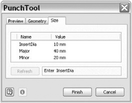
K775.idefrom thePunchesfolder, and click Open. For ease of use, the Punch tool takes you directly to thePunchesfolder and, upon selection of the folder, displays a list of punches. You will notice that every unconsumed center point within the sketch will be populated with the selected punch.Click the Geometry tab, and set the angle to 90.
Click the Size tab, and set InsertDia to 10mm, Major to 40mm, and Minor to 20mm.
Click the Refresh button to preview the results. Figure 7.18 shows the punch parameters.
Then click the Finish button to complete the punch action.
Double-click Flat Pattern in the Model browser to view the flat pattern.
Right-click the Flat Pattern node in the Model browser, and choose Edit Flat Pattern Definition.
Click the Punch Representation tab, set the drop-down to 2D Sketch Rep And Center Mark, and then click OK. Note the simplified version of the punches. This can be useful for placing grouped punches or helping to simplify drawings that have many punches on them.
Note that you could use the Insert iFeature option to place this punch but you would not be offered the same placement options. Instead, it would behave similar to a standard iFeature, requiring constraining of the placed punch by anchoring it to the base feature. In general, it is best to use the Punch tool for sheet-metal parts, rather than placing punches as a standard iFeature. Note that whereas the iFeature tool is available in the standard and sheet metal environments, the Punch tool is available only in the sheet metal environment.
Geometry reuse is a productive technique in Inventor. You can reuse existing features and sketch geometry to create additional features within the same part or even on other open parts. You don't need to create additional new sketches to utilize this technique. The following sections will cover how to copy sketches and features while developing dependent and independent relationships between the features.
Copying features in Inventor is a relatively simple procedure using the Model browser. In an existing model, simply right-click a feature within the browser, and select Copy. Next, select a different face within the model, right-click, and select Paste. Figure 7.19 shows a preview of the placement and the Paste Features dialog box.

There are two questions to consider when copying a feature:
What should Inventor do with features that are built based on the feature you are copying?
What should Inventor do with the dimensions for your new feature?
We'll explore the features first:
On the Get Started tab, click the Open button.
Browse for the file named
mi_7a_031.iptlocated in the Chapter 7 directory of the Mastering Inventor 2010 folder, and click Open.Right-click Extrusion2 in the Model browser, and choose Copy.
Next, right-click anywhere, and choose Paste.
Drag your cursor over any face of the part, and you will see a preview of the copied feature.
In the Paste Features dialog box, set the Paste Features drop-down to Dependent, and you will notice that the fillets are now in the preview as well, because they are dependents of Extrusion2.
Click the front face of the part to position the new feature as shown in Figure 7.19.
Use the +-shaped arrows to move the feature around the selected face.
Use the C-shaped arrow to rotate the new feature, and notice the rotation angle is reflected in the dialog box and can be adjusted there as well.
By default, the dimensions of the new feature will be independent, meaning that because the original feature has a width of 1 inch, the new feature will have the same value, but the two will not be linked. However, if you set the parameter drop-down to Dependent, the dimensions of the new feature will reference the original feature so that if the original width changes from 1 inch to 2 inches, the new feature follows.
Set the parameter drop-down to Dependent, and click Finish.
Locate and edit Sketch2 in Extrusion2, and set the diameter dimension to 0.25 inch.
Finish the sketch, and notice that the new feature follows the edits of the original.
Once you've copied the feature, you should edit the copied feature sketch to properly anchor the sketch on the destination face. When editing a dependent sketch, notice that the dimensions indicate that they are being driven by a parameter from the original feature. If you change the dimensions from a parameter value to numeric value, you will break the dependency with the original sketch.
Cloning is the process of copying feature geometry from one open part to another. The cloning process creates independent features, meaning that the new feature in the new part will have no relationship to the original feature in the original part unless set up manually.
To clone a feature from one part to another, you must first have both parts open in Inventor. Here are the general steps:
From the source part, right-click the feature to be copied in the Model browser, and choose Copy.
Next, switch to the destination part, right-click anywhere, and choose Paste.
Drag your cursor over the face of the part you want to paste onto, and you will see a preview of the copied feature.
Click the face, and then click Finish when the part has positioned to your liking.
The primary difference between copying features within the same part and cloning features between two parts is that parameters can be set to be independent only during the cloning process.
It will be necessary to fully constrain and anchor the feature sketch to the new part once the feature has been copied. To accomplish this, simply edit the new feature sketch and project construction geometry from the new part base feature to serve as anchor points.
You can establish a relationship between two parts, between two assemblies, or between a part and an assembly by linking the files' parameters. This can allow you to place all the design information in one file and link other files to it so that design intent is maintained. Here are the steps to do this:
On the Get Started tab, click the Open button.
Browse for the file named
mi_7a_034.iptlocated in the Chapter 7 directory of the Mastering Inventor 2010 folder, and click Open.This is a simple pin, and you want to link the shaft diameter to a hole diameter in another part. To do this, click the Parameters button on the Manage tab.
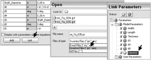
At the bottom of the Parameters dialog box, click the Link button, as shown on the left of Figure 7.20.
Adjust the Files Of Type drop-down to show Inventor Files, and then select the file called
mi_7a_035.iptfrom the Mastering Inventor 2010 folder.This opens the Link Parameter dialog box, allowing you to choose which parameters to link to this part. Click the button next to the parameter named Diameter, and then click OK.
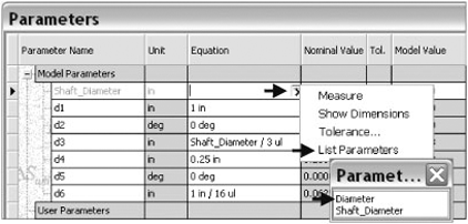
This will add the selected parameter to the user parameters in the pin part. Locate Shaft_Diameter in the list, activate the cell in the Equation column, and clear the existing value.
Click the arrow as shown in Figure 7.21, and choose List Parameters from the flyout.
Select Diameter from the Parameters lists, and choose Done at the bottom of the dialog box.
Lastly, click the Update button from the Quick Access bar (at the top of the graphics area) to see the model update.
Now the shaft diameter is linked to the hole diameter in the part called mi_7a_035.ipt. You can open this part and change the diameter value to see the change carry through to the shaft of the pin. Linking parameters in this way allows you to place design information in one location and pull it into many other parts for automatic updates.
You can see this concept carried through to the assembly level by opening the file called mi_7a_033.iam, where the pin is linked to the hole diameter, so that the pin updates when the hole is changed.
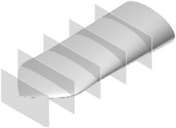
Quite often it is desirable to copy existing part sketches to another location within the same part or a different part. A good example of this would be creating a loft feature where each profile sketch may simply change size.
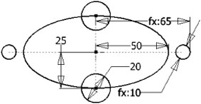
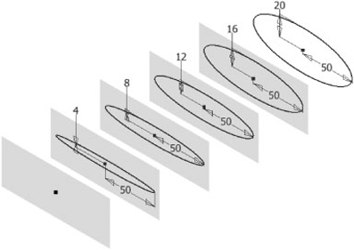
In the example shown in Figure 7.22, the part contains one unconsumed sketch and multiple work planes parallel to the XY origin plane. To copy an existing sketch, simply right-click the target sketch, and select Copy. Then, select the destination work plane, right-click, and select Paste. Pasted sketches are always independent of the original sketch and will create additional parameters for each copy. The following exercise will explore copying sketches.
On the Get Started tab, click the Open button.
Browse for the file named
mi_7a_039.iptlocated in the Chapter 7 directory of the Mastering Inventor 2010 folder, and click Open.Right-click Sketch1 in the Model browser, and choose Copy.
Next, click any edge of the work plane closest to the sketch, and then right-click and choose Paste.
Repeat this for each of the remaining work planes.
Edit each sketch and adjust the minor axis on each of the sketches, decreasing the dimension value by 4mm on each subsequent sketch.
Edit Rectangular Pattern1and change the pattern count to 6.
Right-click any edge of the new work plane, and choose New Sketch.
If not done automatically, project the origin center point to the sketch. You can use the Project Geometry tool on the Sketch tab and select the center point of the ellipse in any of the other sketches.
As you can see, copying sketches can be a quick way to duplicate repetitive geometry. To carry this thought through, you can create a loft utilizing all the sketches including the projected origin point. Apply a tangent condition to the projected point to achieve the result, as shown in Figure 7.23.
In this example, you copied a sketch within the same part. The procedure to copy an existing sketch to another part requires that both parts be open at the same time. Right-click the original sketch, and select Copy. Then, after selecting the destination part work plane or part face in the second file, right-click and select Paste.
Once the sketches are pasted, they can be edited at any time by adding additional geometry, changing dimensions, or simply using the pasted geometry for reference.
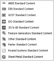
Beginning with Inventor 2010, Content Center is available in two forms: Desktop Content and the traditional ADMS-based Content Center. The ADMS-based Content Center is a set of database libraries based in Microsoft SQL, generally used when sharing a central customized Content Center over a network. The other is a stand-alone install of Content Center that resides on your local machine. The stand-alone install is the default form of Content Center. No matter how you choose to install Content Center, you can choose which libraries to use. These libraries provide standard content in several common international standards, such as ANSI, ISO, and DIN, just to name a few. Figure 7.24 shows the complete list. Once properly configured and populated, Content Center provides an organized method for part and feature reuse.
You can think of these libraries simply as recipes for creating parts, because no actual part files exist in the Content Center file store. Instead, Content Center is a table of part parameters stored in the Content Center database. Once these library databases are installed, you can access them from Inventor and place common parts into your designs.
Understand that it is at this point the Content Center part file is created. Up until this point, the part existed only as a definition in the database table. If you work in a shared environment, the Content Center part files might typically be stored on a network server so that as users collaborate on designs, they have access to the same part files used within the assemblies. Because the Content Center library database files are just definitions of the files, they can be installed on the user's local machines or on a network server, or both.
Content Center provides support for functional design using the Design Accelerator, Frame Generator, and other features within Inventor. When using these tools, the parts generated are pulled from the Content Center libraries. You can use Content Center in conjunction with standard iParts and iFeatures organized within libraries in the project.
Inventor's Content Center, loaded with all the standard libraries, provides in excess of 800,000 variations in parts. To optimize loading, you will want to configure only the appropriate standards for your use. Installing all libraries will cause Inventor to take more time to search and index the data. There are two installation strategies for Content Center. Depending upon how you work, you may want to install the desktop Content Center or the ADMS version.
If you work as a stand-alone user, it is recommended you use the Desktop Content method. No server setup or login is required because the Content Center libraries are installed in the Desktop Content folder on your local hard drive. This is the default installation option. You can insert the install media and install or reinstall the Content Center libraries at any point by following the installation steps. Once the libraries are installed, you simply use the Place From Content Center tool or the Open From Content Center tool to access the Content Center libraries.
If working in a shared group, you will likely want to install Content Center on a server location instead of, or in addition to, the Desktop Content. When installing on a server, you will install the libraries on the Autodesk Data Management Server (ADMS). The ADMS is essentially just the interface with which you interact with the SQL database program. Once the ADMS is installed and the required Content Center libraries are loaded, users log into ADMS through Inventor.
When deciding between installing Content Center libraries on a network server or installing them locally, you should consider whether you plan to create and use a custom library. If not, then there may not be a need to install Content Center on a server, and you can choose to install the libraries on all the local machines only. Because the standard Content Center libraries are all read-only databases, they cannot become out of sync; therefore, two users can access two different instances of the standard libraries and work without issue. If you plan to create custom Content Center libraries, however, it is recommended that you install on a network server so that as the library is updated over time, all users are pulling from the same source. You can consult the installation media for more information on installing ADMS and the Content Center libraries.
Installing all libraries into ADMS will increase your overall memory usage substantially. As mentioned earlier, installing only the libraries you use will keep Content Center efficient. As we will discuss in the coming pages, you can create a custom Content Center library based on the standard libraries and include only what you require. Once the custom library is created, standard libraries can be removed from ADMS. You can add them back at any time by reinstalling them from the Inventor installation disks.
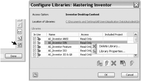
Once you've installed ADMS and the required libraries, you will need to configure the project file to ensure that all required libraries are included in the project. To do this, you will want to close all files in Inventor so that the project file can be edited. Then follow these steps:
In Inventor, go to the Get Started tab, and click the Projects button.
In the Projects Editor dialog box, ensure your project is set active, and click the Configure Content Center Libraries button at the lower right of the Projects dialog box to open the Configure Libraries dialog box, as shown in Figure 7.25.
Use the buttons at the bottom of the dialog box to update, import, add, or remove libraries for the project. Removing libraries from a project will speed up the interaction between Inventor and Content Center when placing a part because fewer library tables are required to be read, searched, and indexed. Once a library is removed, you can add it to the project again at any time.
If you only occasionally access a certain library because you typically do not work with that standard, you might install it but remove it from your Inventor project. When you do need to access this library, simply use the Configure Libraries dialog box to load it for use and then unload it once you are finished. Although the suggestion to add and remove libraries may seem like a hassle, it will pay off in time savings because you will not find yourself waiting for the libraries to load every time you access Content Center.
Content Center is used in many areas of Inventor. Components from Content Center are used in functional design tools, such as the Shaft Generator or Frame Generator, as well as in the use of individual, reusable components in general assembly design. Content Center is also available for use within the part environment using the Place Feature command.
Let's take a closer look at placing components into an assembly from Content Center:
Make sure you have either Desktop Content or the ADMS installed and the ANSI Content Library loaded to continue with this example.
If you are running Content Center through ADMS, ensure you are logged in to ADMS by clicking the Inventor icon

If you are already logged in or logged into vault, Log In will be grayed out and will not be an option in your menu.
Enter your login information, if known. By default ADMS installs with a user account called Administrator with no password set. You can also select the Content Center library's Read-Only check box to access content without logging in.
Specify the name of the server on which you installed ADMS. If you have installed ADMS on your local machine, enter localhost. In the Database text box, enter the name of the ADMS database; the default is Vault.
Once logged in to the ADMS, or if you have installed Desktop Content (there is no login required), you are ready to place parts from Content Center. To do this, follow these steps:
From the Get Started tab, click Open.
Browse for the file named
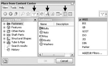
mi_7a_044.iamlocated in the Chapter 7 directory of the Mastering Inventor 2010 folder, and click Open.On the Assemble tab, click the Place From Content Center icon. Check to see that the three buttons as indicated in Figure 7.26 are selected. From left to right these buttons are Filters, AutoDrop, and Tree View.
- Filters button
Select ANSI to filter out all other standards. To turn the filter off after this exercise, simply click the Filters button again and deselect ANSI.
- The AutoDrop button
This turns on the ability to automatically size components based on geometry in the model.
- The Tree View button
This simply splits the screen so that the Category View pane is accessible on the left of the dialog box.
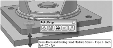
Select the Fasteners category in the left pane, browse to Bolts and then Round Head, select Cross Recessed Binding Head Machine Screw – Type I, and click OK.
In the model, zoom in to one of the castor wheel assemblies, and take note of the empty holes.
Pause your mouse pointer over one of the holes on the castor plate. You will see the AutoDrop icon activate and flicker as Inventor indexes the database for an appropriate size. If no matching size can be found in the database, a cursor note will appear saying so. If an appropriate size is found, a cursor note will display it, and a preview of the part will be shown.
Once the size appears, click the edge of the hole to set the screw in place. The AutoDrop toolbar will appear along with the red grip arrow.
Drag the grip arrow up or down to specify the length of the screw. Note that only lengths found in the database are available.
Click the Apply button, and continue placing screws as you see fit. Experiment with placing the mouse pointer over one of the large diameters in the castor assembly to watch AutoDrop attempt to find an appropriate size. Figure 7.27 shows the AutoDrop toolbar.
Here is a brief description of each of the tool icons shown in the AutoDrop toolbar in Figure 7.27:
- Insert Multiple
The first icon is available when Inventor identifies multiple targets that are like the selected target. In this case, the other holes in the plate are picked up and previewed. If you apply the screw now, four screws will be placed at once. If you do not want the multiples to be placed, you can click the Insert Multiple icon to turn it off.
- Change Size
The second icon is grayed out while Insert Multiple is on. It inserts the part and opens the Part Family dialog box, which allows you to edit the component.
- Bolted Connection
The next icon opens the Bolted Connection Component Generator and allows you to place bolts, nuts, and washers sets as a group.
- Apply
The fourth icon sets the previewed component(s) and allows you to continue placing more components of the same family.
- Done
The last icon sets the component(s) and exits the AutoDrop mode.
The AutoDrop toolbar is context sensitive, meaning that the icons may vary depending upon the component to be placed and the selected geometry. If you press F1 on the keyboard while the AutoDrop toolbar is displayed, Inventor will open the help file and list all the icons and their descriptions.
Now that you've placed Content Center components, let's examine where Inventor is filing the newly generated Content Center files. Go to the Tools tab, and click Application Options; then click the File tab. Look for the file path indicating the default Content Center files, as shown at the top of Figure 7.28.
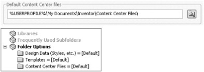
This is where Inventor will place all standard parts placed from Content Center by default. Typically you should change this path to a path that is on the network server, particularly if you're working in a multiuser environment. If you work only on your local hard drive, you will still likely want to change the path to be similar to the path where you save your Inventor designs.
If this path is left at the default, Content Center part files will be saved on your local machine. This causes a problem when a co-worker opens an assembly you created. There is one more place where you can set this path, and that is in the project file under Folder Options, as shown at the bottom of Figure 7.28. It is important to note that a path set in the project file takes precedence over a path set in Application Options. If the project file is set as Content Center Files = [Default], then the files are stored at the Application Options path.
Only standard Content Center files are stored at this location. Custom-sized Content Center part files, such as standard steel shapes, pipes, and so on, are stored at a path chosen by you at the time of their creation.
Standard Content Center libraries supplied with Inventor are designated as read-only and cannot be modified. If you need to create custom part libraries or modify standard content such as adding part numbers or material types, you can do this by creating a custom Content Center library. Custom libraries are initially set as read-write libraries so that you can add and modify content.
You add libraries from the Autodesk Data Management Server Console when using Content Center with the ADMS. You can access the ADMS by selecting Start
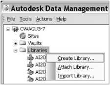
Once logged into the ADMS Console, expand the folder in the top of the left pane, right-click the Libraries subfolder, and select Create Library. Create a new library called Mastering Inventor.
Once the library is created, follow these steps:
You can create a custom Content Center library for Desktop Content through the Content Center configuration of the Projects editor. To do this, follow these steps:
Go to the Get Started tab.
Click the Projects button.
Click the Configure Content Center Libraries button at the bottom-right corner of the Project Editor dialog box.
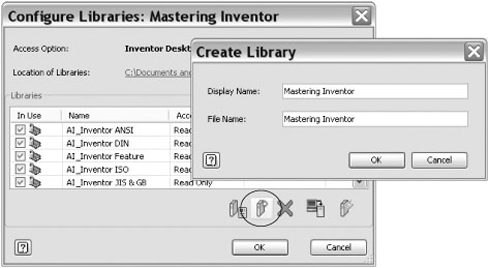
Click the Create Library button, and enter Mastering Inventor into the input box, as shown in Figure 7.30.
Click OK.
Ensure that the In Use check box for this new library is selected so that the project is configured to include it.
After creating a custom library, you can copy entire or partial contents of existing standard libraries into your custom library. You might use this process when you want to simplify one of the standard libraries, remove portions of the library that are not needed in your work environment, or edit component properties such as part numbers. Here are the steps to copy families to a custom library:
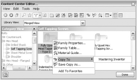
Access the Content Center Editor from within Inventor by going to the Tools tab and clicking the Editor button on the Content Center panel. This editor looks similar to the Content Center dialog box.
Locate the library or the part family within a library that you want to copy, right-click, and choose Copy To

The library must be included in the project file configuration list in order to be visible within the editor. If you copy an entire library to your custom library, then the entire folder structure and contents will be replicated in your custom library. If you copy an individual part to your custom library, then only the affected category structure will be replicated in the custom library along with the copied part.
To copy only a portion of the category structure, browse to the last hierarchical portion of the structure that you want to replicate. Otherwise, starting from the top and copying the structure will replicate the entire structure.
Each category within Content Center contains category properties. Within the category properties is general information regarding the category itself. The General information tab contains the category name, category image, and source library.
The Parameters tab contains parameters used within the category to assist in the description of parts located within that category. Figure 7.32 illustrates the parameter list in the ANSI Socket Head category.
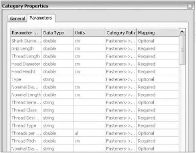
Within the parameters shown earlier, some are optional and some are required. If you are placing a part within this category, you must map your part properties to all required fields for proper operation. Optional fields do not require mapping.
What this means is if you are planning on publishing a large number of your own parts to Content Center, then your part parameters must match the category parameters. If you are unable to match the parameters, then consider creating a new category.
Right-clicking an individual Content Center part will allow you to view the family properties and mapping of that part. Compare the category parameters of the part with the parameters of the intended category. Matching the two parameter lists ensures that the part will map easily into that category.
A Content Center family is an individual part, similar to an iPart. The part consists of a standard factory part with a family table attached that generates any of the optional table values.
You can edit any individual part by first switching the library view to your custom library designation, as shown in Figure 7.33.
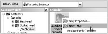
In the previous example, we switched the library view to the Mastering Inventor custom library. Right-click a part located within the custom library, and select Family Table. This launches a dialog box that allows the user to modify values, copy/paste, add/delete rows, or suppress existing rows within the table. The dialog box also allows the addition, deletion, and modification of columns and properties.
Developing a process for reusing parts within your company's design environment is essential for standardization and improved productivity. Part of this process may include publishing existing Inventor parts stored in project libraries. Both normal parts and iParts can be published to a custom Content Center library.
The act of publishing a standard part into the custom library adds a family table to the published part. Exported Part parameters will be converted to table parameters when published to the Custom Content Center. iPart tables are converted to family tables when published.
If the part you intend to publish will be included in an existing Content Center family category (that is, fasteners, shaft parts, and so on), you can use the Component Authoring tool to prepare components with the necessary properties for use as "smart" content in the Content Center Library. You can do this by following these steps:
On the Get Started tab, click the Open button.
Browse for the file named
mi_7a_064.iptlocated in the Chapter 7 directory of the Mastering Inventor 2010 folder, and click Open.Go to the Manage tab, and click the Component Authoring button on the Author panel.
From the drop-down list, select Fasteners
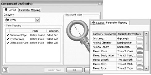
Select the geometry for each row in the dialog box that corresponds to the dialog box graphic in order to map iMate placement to this part (iMates are preprogrammed assembly constraints).
Click the Parameter Mapping tab. Note that the parameters listed in the light yellow/orange rows are required, whereas the others are optional. Click the ... button for the Grip Length row.
In the Part Template Parameters dialog box, expand the browser to find Parameters
Map the Nominal Diameter and the Nominal Length to the NomDiameter and NomLength model parameters, respectively (you can find these at Parameters
Click the OK button to write the mapped parameters and iMates to the part file. You could also click the Publish Now button to start the publishing process.
You can author parts ahead of time and use the Batch Publish tool to publish one or more unopened parts at once. Or you can publish one part at a time as covered in the next section. Figure 7.34 shows the Component Authoring dialog box tabs.
To publish a part to Content Center, you must have a custom library with read/write capability created, and your current project file must be configured to include this custom library. In this example, you will publish a simple part that has already been authored to the custom read/write Content Center library called Mastering Inventor. If you haven't already created this library, review the steps in the "Creating Custom Libraries" for desktop content of ADMS, depending on which method applies to your setup.
On the Get Started tab, click the Open button.
Browse for the file named
mi_7a_068.iptlocated in the Chapter 7 directory of the Mastering Inventor 2010 folder, and click Open.Go to the Manage tab, and click the Publish Part button on the Content Center panel.
Select the Mastering Inventor library, and set the language as required; then click Next.
Ensure the Category To Publish To is set to Fasteners
Notice most of the parameters are already mapped, because this part has previously been authored per the steps in the "Preparing the Part for Publishing" section. Recall that all parameters in the light yellow/orange rows are required. Click the ellipsis button (the three dots) for the Thread Type row.
In the Part Template Parameters dialog box, expand the browser to find Threads
Select Nominal Diameter, Nominal Length, and Part Number in the left pane, and use the arrow button to include them in the right pane. This defines keys that are available for selection upon placement of the Content Center part once published. At least one Key column must be defined. Click Next to continue.
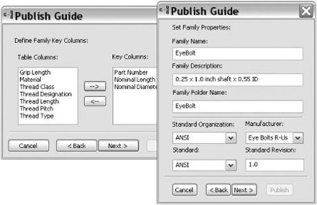
Enter EyeBolt for the family name, and set the Standard Organization option to ANSI. Only the family name is required; however, designating the Standard Organization option allows the part to be listed when filtering per standard. You can also type a custom standard into the field. This allows you to create a filter for the parts you published.
Click Next, and notice the preview thumbnail. You can use the Browse icon to select a different graphic file for use as a thumbnail, if one exists.
Click Publish to complete the task and add this part to your custom Content Center library. Click OK in the successful publish confirmation box.
This creates the part family table in the Content Center library, but at this point there is only one row in the table. Typically you will want to add a row for each size or different type of the component. You can do this by using the Content Center Editor (found on the Manage tab). Figure 7.35 shows the family key and properties steps of the Publish Guide.
You can also convert a part to a table-driven iPart before publishing and include the rows for each size and type of the part configuration in the iPart table. Once you have a workable iPart that behaves correctly, you can then open the original factory iPart and publish the part. The iPart may be a custom iPart or a fully table-driven factory. iParts containing multiple row definitions in the table will convert to a fully table-driven Content Center part. You can find more information on iParts in the "Working with iParts" section at the beginning of this chapter.
Before using a newly published Content Center component in production, test the part in a blank assembly for proper function.
Adding a New Category to Content Center
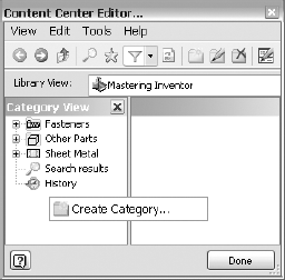
If you need a unique category for your own specific parts, you can simply add a new family of parts instead of using an existing category. You can do this from the Content Center Editor (accessed from the Manage tab). Make sure the library view is set to view only the read/write library you intend to create the new category in and that the tree view is enabled. Then right-click in the blank space in the Category View pane, and choose New Category. You can also create a subcategory by right-clicking an existing category and selecting New Category.
- Create and modify iParts
iParts are the solution to creating parts that allow for an infinite number of variations without affecting other members of the same part family already used within your designs.
- Master It
You use a purchased specialty part in your designs and would like to create the many size configurations that this part comes in ahead of time for use within assembly design.
- Create and use iFeatures and punches
Creating a library of often-used features is essential to standardization and improved productivity within your design workflow.
- Master It
You want to be able to place common punches, slots, and milled features quickly, rather than having to generate the feature every time.
- Copy and clone features
You do not have to create iFeatures in order to reuse various part features in your designs. If a part feature will have limited use in other designs, it is often better to simply copy it from part to part or from face to face on the same part.
- Master It
You need to reuse features within a part or among parts. You consider iFeatures, but realize that this feature is not used often enough to justify setting up an iFeature.
- Link parameters between two files
Linking design parameters between two or more files allows you to control design changes from a single source, making it easy to update an entire design from one file.
- Master It
You want to specify the overall length and width of a layout design in a base part and then have other components update as changes are made to this part.
- Configure, create, and access Content Center parts
Content Center provides a great opportunity to reuse database-created geometry within assemblies and within functional design modules. The Content Center Editor provides the means to add custom content into Content Center. You can create and add custom libraries to your current project file.
- Master It
You would like to change the part numbers in some Content Center components to match the part numbers your company uses. You would also like to add proprietary components to Content Center.