
Working with large assemblies is more manageable than ever before with fully native 64-bit support, removing the memory limitations related to the Windows XP 32-bit platform. Large assembly design on 32-bit systems is improved in Inventor with the use of tools such as shrink-wrap and substitution level of detail (LOD) representations. These LODs allow you to swap out complex subassemblies with single substitute parts of less detail, all while maintaining model properties and an accurate bill of materials.
Although every design department may have a different view on what a large assembly is, everyone can benefit from the large assembly tools and strategies discussed in this chapter. You can create fully functional digital prototypes ranging from 10 to 100,000 components if you approach the task with an eye to the topics covered here.
In this chapter, you'll learn to:
Select a workstation
Adjust your performance settings
Use best practices for large assembly
Manage assembly detail
Simplify parts
Ensuring that you have an adequate system to accomplish the type of design work you intend to do is an important, but often overlooked, step in achieving successful large assembly design with any parametric modeler. Understanding the capabilities and limitations of your computer and then budgeting for upgrades is an important part of working in today's design world.
If you consider the time you spend waiting and the loss of work experienced when working on an undersized computer, you will likely determine that a workstation upgrade will pay for itself within a year. If you budget for upgrades every two years, then you could argue that the upgrade is actually paying for itself in the second year of use. Although this scenario might not fit your actual situation, it demonstrates the idea that operating costs (hardware and software alike) should be budgeted and planned for and always measured against lost work and downtime.
When your system runs low on physical memory (RAM) and requires more to complete an operation, Windows begins writing to the system hard drive in order to continue. This is known as virtual memory and is often referred to as a page file.
When considering a workstation for doing large assembly design, it should be your goal to always work in RAM as much as possible, because when Windows begins to write to virtual memory, you will notice a considerable drop in performance. One of the weakest links in terms of speed on even the most adequate workstation is the hard drive. Accessing data from RAM can be thousands of times faster than accessing data from the hard drive. Therefore, one of the best ways to beef up a workstation is to simply add more RAM.
If you are running an older computer or skimped on RAM when you upgraded, you will notice that as you attempt to load large assemblies or drawing files of large assemblies in Inventor, you quickly use up available RAM. You will find yourself waiting for Windows to write and then read data to the hard drive. Although the unknowing user might think that Inventor has suddenly become slow, you should understand that no application can overcome the hardware and operating system limitations upon which it is installed.
If you run out of RAM on a 32-bit system, you have a limit of 4GB of virtual address space. Windows reserves 2GB of that space for the operating system by default, thereby leaving just 2GB for all the other running applications. If you work on extremely large assemblies, you might exceed the available 2GB of address space.
To resolve this, it is possible to configure Windows to reserve only 1GB of address space for the operating system and leave 3GB for the applications to use. This is referred to as "flipping the /3GB switch." Depending upon the size of the assemblies you work on, the configuration settings you adjust in Inventor, and the techniques you employ within Inventor, the extra 1GB of virtual memory might be adequate for your needs for those instances when you need a bit more memory. However, as stated earlier, it should be your goal not to be working in virtual memory but instead to always be working in RAM.
Please note that the /3GB switch was developed for server operating systems and therefore is considered a workaround when being used on a workstation. Although you may be able to employ this startup modification to your system, understand that it is an unsupported workaround and has been known to cause stability issues. Also note that some workstations may not permit this modification at all.
If you do utilize the /3GB switch, be aware that although this does allow you to extend your system's capabilities, it may effectively create more "rope to hang yourself," meaning that it will allow you to build large assemblies that you can load but then cannot save or modify. Often this results in a crash of the application and the generation of errors and file corruptions. Therefore, consider this an option at your own risk, and use it to supplement your workstation capacity for the short term, but be careful of overextending the use of virtual memory. You can find instructional information on the /3GB switch on the Microsoft support website (http://support.microsoft.com/).
The maximum amount of RAM that is supported on a Windows XP Professional 32-bit system is 4GB. If you determine that your needs currently exceed or will soon exceed the limits of a 32-bit system, you should consider a 64-bit workstation; 64-bit systems can handle up to 128GB of RAM and therefore do not have to slow down to write data to the virtual memory.
Most processors purchased by the time this book was published will be 64-bit. Understand that you must also run a 64-bit operating system, such as Windows XP Professional 64 or Windows Vista, in order to gain the performance increases attributed to a 64-bit system. Although Inventor 2008 was compiled to run on a 64-bit operating system, Inventor 2009 was the first fully native 64-bit version. All versions since Inventor 2009 take full advantage of a 64-bit system.
Hardware upgrades are an important part of any design department. Budgeting properly and knowing what components to allocate more money to can make these upgrades more manageable. Dollar for dollar, you should give priority to the following components in the order listed.
Although the minimum system requirement for Inventor 2010 is 1GB, you should always consider adding as much RAM as you can afford to your workstation. If making the move to a 64-bit system, you will require a minimum of 4GB of RAM, and you should consider at least 8GB.
To ensure that your graphics card is set at the optimal settings, select the Tools tab, click Application Options, and go to the Hardware tab in the dialog box that opens. Direct3D graphics hardware is the default setting for Windows XP Professional 32-bit and 64-bit versions as well as Windows Vista 32-bit and 64-bit versions.
Inventor 2010 will use either OpenGL or the default DirectX 9 hardware acceleration modes when running Windows XP. Windows XP 64 uses DirectX 9 only. Windows Vista 32 and 64 support DirectX 9 and 10. Inventor will automatically detect the appropriate level for your card. All configurations have OpenGL software emulation.
It is recommended that you consider a midrange graphics card for an Inventor workstation and save the money for frequent upgrades rather than investing in a high-end card, because of the rapid changes in video card technology. For recommendations on graphics cards and other hardware, refer to the following websites:
Autodesk Inventor hardware:
www.inventor-certified.com/graphics/Certified workstations:
www.inventor-certified.com/graphics/cert_ws.phpAutodesk Inventor hardware graphics database:
www.inventor-certified.com/graphics/registries.php
Inventor files are segmented, meaning that the graphics are separate from the feature information. When an assembly is first opened, only the graphics segments are loaded. When you edit a file, the additional data is loaded at that time. This makes a fast hard drive important for performance.
Another aspect of hard drive performance stems from file storage and workspace setup. In Inventor, working from your local drive is the preferred method, and Autodesk recommends you avoid working on Inventor files across a network. The reason for this is simply because of the numbers of files that you might be editing at one time. For instance, a change to a large assembly could potentially modify hundreds of part files, requiring all those files to be saved at once. Doing this across a network, particularly one with latency issues, may result in file corruptions if the files are not saved correctly. Autodesk Vault is set up to store files on a server and copy those files locally when checked out for editing. When working in this manner, Inventor has a higher-performance requirement than standard office applications, and the hard drive workload is very heavy. Therefore, upgrading your hard drive to a higher-speed SATA or serial attached SCSI (SAS) drive may be worth considering.
When considering processors for an Inventor 2010 workstation, the chief question should concern multicore processors. As a minimum, you should consider a dual-core processor even though Inventor is not truly a multithreaded application. (Multithreaded means that the operating system or the application will spread the processing load across the processor.) If you opt for a dual-core processor, you can still take advantage of it, because Inventor will run on one core and other applications will run on the other.
There are parts of Inventor, such as Inventor Studio's rendering engine, that are multithreaded, so if you plan to do a lot of image and animation rendering in Inventor, you may want to opt for a quad-core processor. Otherwise, if you are trying to decide between a dual-core and quad-core processor, it will probably be more cost effective to go with a faster dual-core processor rather than a quad-core processor. This will likely change as the rapid pace of technology continues.
Whether or not upgrading workstations is an option, you should ensure that your system is set up for optimal performance when working with large assemblies. A number of options in Inventor will facilitate better performance when working with large assemblies.
Generating and hiding lines when creating and editing drawing views in Inventor can be some of the most processor-intensive tasks in Inventor. To help ease the demand on the system, you should be aware of several settings when working with large assembly drawings. You can find these settings by selecting the Tools tab, clicking Application Options, and going to the Drawing tab in the dialog box that opens, as shown in Figure 9.1.
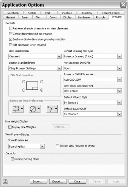
The Display Line Weights check box enables or disables the display of unique line weights in drawings. Deselect the box to show lines without weight differences. Line weights will still print correctly even with this box selected. Deselecting this box will speed up the performance of your drawing during edits and annotation work.
The options in the Show Preview As drop-down box set the type of preview you get when creating a view. All Components is the default, but you will find that selecting the Partial or Bounding Box option will improve performance because Inventor will not be required to create and update the preview as you drag your mouse pointer around the screen. The preview setting does not affect the drawing view result. Bounding Box previews a simple rectangle during the view creation, and Partial previews a simplified representation of the view. Bounding Box is the most efficient.
When using this option, you can still preview the assembly if you'd like by simply selecting the Preview check box in the Drawing View creation dialog box, but the default will be a simple bounding box. Using the Bounding Box option is suggested if you find yourself waiting for the preview to generate during drawing view creation.
The Section View Preview As Uncut check box will also provide some performance improvements when selected. This option will allow Inventor to display the section view preview as unsectioned in order to be more efficient. The section view will still be generated as normal.
Memory Saving Mode sets the way that Inventor loads components into memory during view creation. When this option is selected, Inventor loads components into memory before and during view creation and then unloads them from memory once the view is created.
Although memory is conserved using this mode, view creation and editing operations cannot be undone while this option is enabled. You'll notice the Undo/Redo buttons will be grayed out after a view creation or edit. This option will also have a negative impact on performance when editing and creating views because the components must be loaded into memory each time. Because of this, you should consider setting this option as an application setting only if you always work with very large assemblies.
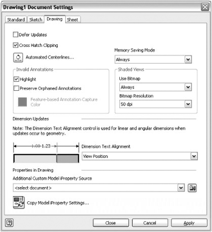
It is generally preferred to set this option per document by selecting the Tools tab, clicking Documents Settings, going to the Drawing tab in the dialog box that opens, and then setting the Memory Saving Mode drop-down list to Always, as shown in Figure 9.2.
Also in the document settings, you can adjust the way that shaded views are displayed. Setting the Use Bitmap drop-down list to Always, as shown in Figure 9.2, improves performance by applying raster shading as opposed to a vector style. The difference impacts the display but typically does not affect printing.
You can also adjust the bitmap resolution; setting it lower conserves memory and speeds up performance. The default is 100 dpi. Setting the dpi to 200 or higher will invoke a prompt, warning you that increasing this setting for large assemblies may not be possible.
When working within the modeling environment, you can adjust several settings to have a positive impact on performance. You can access these settings by selecting the Tools tab, clicking Application Options, and going to the Display tab in the dialog box that opens, as shown in Figure 9.3.
Deselecting the Edges check box for Enabled components in the Shaded Display Modes area of the Display tab will lighten the amount of graphics rendering required to display and update the display of your large assemblies.
Setting the Display Quality drop-down list to Rough, as shown in Figure 9.3, will speed up performance by simplifying details. Navigation commands such as zooming, panning, and orbiting are particularly affected by this setting. If you find that the rough display is not to your liking, you can toggle back and forth according to the size of the assembly model you are working with.
The View Transition Time (Seconds) setting controls the time required to smoothly transition between views when using zooming and viewing commands. A zero transition time takes you from the beginning view to the end view instantaneously. For instance, if you were zoomed in on a small component and wanted to zoom all while this slider was set to zero, you would not see the gradual zooming out that may provide a gain in performance but can make changes in position and orientation less clear.
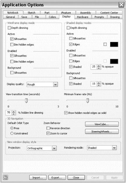
You can use the Minimum Frame Rate (Hz) setting to specify how slowly the display updates during zooming and orbiting commands. It may be hard to see the effects of this option on a normal-sized part or assembly, because the views will typically update more quickly than the rate of this setting. Here is a quick description of the how the slider setting corresponds to the frame rate:
0 always draws everything in the view, no matter the time required.
1 tries to draw the view at least one frame per second. (Inventor will simplify or discard parts of the view if needed but will restore them when movement ends.)
5 draws at least five frames per second.
The following are a few general settings that you can adjust to help large assembly performance. You can access these settings by selecting the Tools tab, clicking Application Options, and going to the General tab in the dialog box that opens, as shown in Figure 9.4.
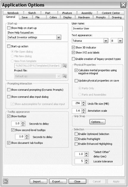
The Enable Optimized Selection setting, located on the lower-right corner of the dialog box, improves the performance of graphics during prehighlighting in large assemblies. When activated, the algorithm for the Select Other function filters for only the group of objects closest to the screen. If you click through this first group of objects, the next group is considered for highlighting.
When checked, the Update Physical Properties On Save setting, located in the Physical Properties area on the right side of the dialog box, recalculates the mass properties of the model when you save the file. This ensures that mass properties are up-to-date. Setting this to Parts Only will ensure that the parts are all up-to-date without requiring you to wait on the recalculation for large assemblies. Note that this setting is disabled altogether by default but is recommended to be set to Parts Only if you find it helpful. Note too that the same function can be performed manually from the Bill Of Materials Editor and the Manage tab.
The Undo File Size option, on the lower-right side of the dialog box, sets the maximum size of the temporary file that records changes to a file so that actions can be undone. It's typically required to increase the size of this setting when working with large models and drawings, because each undo action is typically a larger calculation. Autodesk recommends adjusting this in 4MB increments.
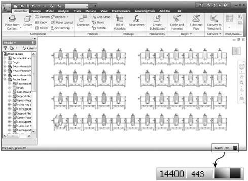
The Capacity Meter is displayed at the bottom-right corner of the Inventor screen, as shown in Figure 9.5. The meter has three memory use indicators. The number to the left is the total number of occurrences in the active document. The next number is the total number of files open in the Inventor session. The last indicator is a colored bar graph that displays the amount of memory used by the session. When hovering your mouse pointer over the Capacity Meter, a tool tip will display the details of used and available memory. In 32-bit systems, you can use the meter in two modes: Inventor Only and Physical Memory. In 64-bit systems, the Inventor Only mode is not available.
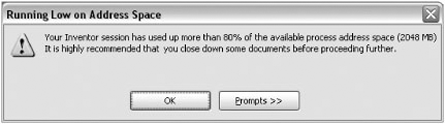
On 32-bit systems the Capacity Meter display is set to look at just the Autodesk Inventor process. The bar color will change from the normal green to yellow when more than 60 percent of the allotted address space has been used. It will then turn red at 80 percent, and a warning dialog box will prompt you to close documents in an attempt to free up memory, as shown in Figure 9.6.
As a rule, you should not habitually work when the meter indicates that you have passed the 60 percent mark. When you do see the bar turn yellow, you should stop and create an LOD representation or close some files. LOD representations are covered later in this chapter. Working in limited memory can lead to memory corruptions in the file and result in a loss of work.
Typically what happens when a user continues to work past the 60 percent range is that some memory-intensive calculation is performed that will cause the virtual memory to fill and then have to "swap" out a large amount of data. During this time, your system may become unresponsive and any well-intentioned attempt to help may cause file corruptions.
Other common results of working past the 60 percent marker occur when saving or creating a drawing view. When working in this manner, it is possible to reach a point at which you will not have enough memory available to save the files. The same can happen when attempting to create drawing views of an assembly when you have reached this marker.
Therefore, you should not work past the 60 percent marker, other than to create LODs and/or to take other actions to reduce the amount of memory your file is requiring.
On 64-bit systems the Capacity Meter display indicates the entire system's RAM. The green portion represents the Inventor session, while the yellow portion is all other applications. This mode is disabled if you do not have administrative rights on your workstation or if process monitors have been restricted on your system.
You can adjust several settings in the operating system to help with performance. Setting the page file to twice the amount of RAM is common among Inventor users in order to gain performance. There are also many visual effects that you may have grown accustomed to that actually cost you resources. If you are serious about turning your workstation into a large assembly workhorse, it is advisable to disable these features.
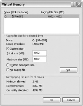
To change the size of the virtual memory paging file in Windows XP Professional, right-click the My Computer icon, and choose Properties. On the System Properties tab, click the Advanced tab, then click Performance Options, and finally under Virtual Memory click Change.
In Windows Vista, right-click the Computer icon, and choose Properties. On the System Properties tab, click the Advanced System Settings tab, then click Performance Options, and finally under Virtual Memory deselect Automatically Manage Paging File Size For All Drives. Then click Change.
Select Custom Size, set the Initial Size and Maximum Size settings to twice the available RAM, and click Set, as shown in Figure 9.7.
Windows provides many options to set the visual effects of your computer. Many of them have a surprisingly high impact on performance when memory is scarce. Here are a few you might consider disabling in order to conserve resources:
- Screen saver
Select Control Panel

- Visual settings
Right-click the My Computer icon, and select Properties. Go to the Advanced tab, and click the Settings button under Performance. Select Adjust For Best Performance. Windows will set back to a classic look and run much faster overall.
- Appearance effects
Select Control Panel
- Screen resolution
If you're fortunate enough to have a nice, large-screen monitor, you probably have set the screen resolution up to maximize your space. However, this may be working against your large assembly pursuits. Experiment with setting the screen resolution to a lower setting such as 1024×768 to see whether you gain any performance when working with large assemblies.
Oftentimes Inventor users don't think about large assembly performance until it has already become an issue with the model on which they are working. It is possible for two Inventor users working on two identical workstations to create two seemingly identical models, and yet those two models might perform in dramatically different ways.
If the first user has been mindful of large assembly management all along, his model and drawings will be much easier to open and work with. If the second user concentrated only on her design and gave no thought to the memory demands of the files she was creating, her model will be slow to open and work with and ultimately more likely to cause application crashes and data corruption. When the next job comes along, user 1 can reuse his model to create a similar design, while user 2 will likely re-create the assembly model because she does not trust the integrity of the first model she created.
Understanding where performance savings can be gained as you create the model will help pay off once the large assembly is created and will make it much more manageable to work with along the way. And of course, a large assembly model can be revisited and cleaned up according to best practices to make it more manageable as well. Either way, having a model that is manageable and can be reused for similar work in the future should always be your goal.
You should be considering large assembly performance at three stages:
Creating and editing the model
Opening the model
Detailing and annotating the model
You can use several methods to ensure that your large assembly will not become unmanageable. It is important to remember that the words large assembly are subjective. To you, a large assembly may be 200 components, whereas to someone else it may be 20,000. Either way, following best practices ensures that you are developing good procedural habits and are prepared for the day when you are asked to design a much larger assembly than you typically do today.
As was discussed earlier in this chapter, hardware limitations might be an obstacle that you cannot overcome even if you follow every best practice, but you'll need to follow these practices to know that for certain. Conversely, even if you have a workstation that is extremely capable, you will still benefit by developing good work habits and making your models easier to handle on less capable workstations of others you collaborate with.
Using subassemblies within upper-level assemblies can reduce assembly constraints. The importance of this concept cannot be overstated. Reducing assembly constraints can eliminate the number of redundant calculations Inventor must make to solve your model, and therefore it pays off immediately in that respect. The increased organization and ability to reuse components already organized into subassemblies is a benefit that may be realized in future.
To reorganize an assembly that has not been created using subassemblies, you can use the Demote option. To explore this concept, select the Get Started tab and choose Open. Browse for the file named mi_9a_001.iam located in the Chapter 9 directory of the Mastering Inventor 2010 folder, and click Open.
Although not a large assembly by anyone's standard, this assembly has been created without using subassemblies to demonstrate the ability to demote components into subassemblies from the top down. Your goal is to restructure this assembly into three subassemblies so that you can reduce constraints and create subassemblies that can be used in other stapler designs. To do this, follow these steps:
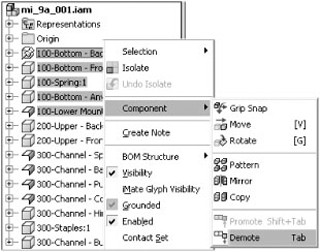
In the Model Browser, select all the components with a prefix of 100.
Once you've selected those components, right-click and choose Component
You will be presented with a Create In-Place Component dialog box, where you can specify the name of the new subassembly, the template file, the file location, and the default BOM structure. Enter 100 for the name, and click OK.
Click Yes in the warning stating that assembly constraints will be moved with the demoted components, as shown in Figure 9.9.
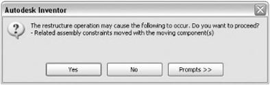
This warning simply states that any constraints between the 100 series parts and the 200 and 300 series parts will now be redefined to be between subassembly 100 and the 200 and 300 series parts. The constraints between the 100 series parts and other 100 series parts are maintained in subassembly 100.
This is important in large assemblies because it can significantly reduce the number of constraints used. Consider the five components you selected to demote in the stapler. If these components all had just one assembly constraint each relating it to some part that will not be in the new subassembly, then those five constraints will be discarded.
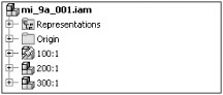
Continuing with the example, you should now see the subassembly named 100.iam in the Model Browser. Because of the restructure, you will need to ground the assembly so that it cannot be accidentally moved. Then you can continue and demote components into another subassembly:
Right-click
100.iam, and click Grounded to set it in place.In the Model Browser, select all the components with a prefix of 200.
Right-click, and choose Component
Enter 200 for the name, and click OK. Click Yes in the warning dialog box.
Repeat the steps for demoting for all the components with a prefix of 300 until your browser looks like Figure 9.10.
You can restructure components by dragging a component within the assembly browser from in and out of a subassembly. Moving components up out of a subassembly is called promoting rather than demoting. It is also important to understand that when you demote and promote components, you may need to edit the subassembly and ensure that components are constrained properly within that subassembly.
Too many cross-part adaptive features can cripple the performance of even a modest-sized assembly if used without discretion. As discussed in Chapter 8, adaptivity should generally be turned off once the adaptive feature or part is created.
Often features and parts are made adaptive during the early design stages of a model, when changes are made quickly and you want many parts to follow these changes. Turning off the adaptive status in the part ensures that your assembly performance will not be affected. If the adaptive part needs to be edited, you can turn on its adaptive status so that you can make adjustments.
Many times parts become adaptive by default when creating a new part or feature in an assembly because a reference sketch is projected from one part to another. You can disable this by going to the Tools tab, clicking Application Options, going to the Assembly tab in the dialog box that opens, and then deselecting the Enable Associative Edge/Loop Geometry Projection During In-place Modeling option under Cross Part Geometry Projection. This will create fewer accidental adaptive parts but may require more manual effort in projecting geometry across parts.
When working with a large assembly, combing through all the many parts within that assembly that you want to select for a given task can be time-consuming and difficult if you attempt to locate them using the standard Pan, Zoom, and Orbit methods. Instead, make yourself familiar with the options in the assembly selection tool.
You can use selection tools to suppress sets of components based on such factors as size or on internal components that are not visible because of the presence of external housings, and so on. For instance, to maintain performance, you may not want to load all the internal components into memory when they are not important to your current design task. Once you've selected the internal components, you can suppress them and create an external part-only LOD representation.
Another use of assembly selection tools is to create view representations in the assembly to aid in the creation of views in the drawing file. As an example, when you place a view in the drawing using a design view that was created using the All In Camera tool, only the components in the screen view plane are calculated. This increases performance and memory capacity. Figure 9.11 shows the available selection tools.
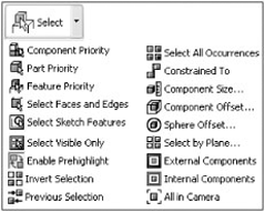
The following are the selection tools:
- Component Priority
Sets the selection to pick up the topmost structure level of components. If set, this will pick up subassemblies and not their children.
- Part Priority
Sets the tool to select parts no matter their subassembly structure.
- Feature Priority
Selects individual features rather than the parts that contain them.
- Select Faces And Edges
Allows you to highlight and select faces or the curves that define those faces.
- Select Sketch Features
Allows you to highlight and select sketches or the curves that define those sketches.
- Select Visible Only
- Enable Prehighlight
Displays prehighlighting when your cursor moves over an object. This does not affect the Select Other tool, which always shows prehighlighting.
- Select All Occurrences
Selects all instances in the current file of the selected component.
- Constrained To
Selects all components constrained to a preselected component or components.
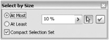
- Component Size
Selects components by the percent set in the Select By Size box. Size is determined by the diagonal of the bounding box of the components. Click the arrow to select a component and measure its size to use as a scale. Figure 9.12 shows the Select By Size box.
- Component Offset
Selects components fully or partially contained within the bounding box of a selected component plus a specified offset distance.
- Sphere Offset
Selects components fully or partially contained within the bounding sphere of a selected component plus a specified offset distance.
- Select By Plane
Selects components fully or partially intersected by a specified face or plane.
- External Components
Selects external components based on a percentage of the component's viewable surface.
- Internal Components
Selects internal components based on a percentage of the component's viewable surface.
- All In Camera
Selects all components in the current view screen based upon a percentage of the component's viewable surface.
View representations are often used in large assemblies to navigate to a predefined viewing angle so that you do not have to tax your system with heavy graphics regeneration. For instance, if you have an assembly that contains an entire production line of material-handling equipment, you may find it difficult to orbit around to the backside of the assembly in order to complete a simple task such as selecting a face or just looking at the assembly. If you set a design view before orbiting and then set another once you have orbited to the desired view, you can then easily toggle between the two views of this assembly, thereby increasing performance during navigation between these predefined views.
View representations have other large assembly benefits as well. When creating a drawing view of a large assembly, you can specify a preset view representation and reduce the time it takes to create the drawing view. If you have turned the visibility of some components off in the assembly view representation, the drawing view can generate even faster and provide you with a clearer and more concise view. Of course, if you already have the assembly open when creating the drawing view, the components are likely already loaded into memory.
Another way that the experienced Inventor user may use view representation is to navigate the Model Browser. For instance, if you set up a view representation to zoom in on a particular subassembly so that you can navigate to that component quickly, you can save that view representation while the entire model tree is rolled up and only the subassembly of interest is expanded. This browser state will be saved within the view representation.
Once a view representation is created, you can right-click it and choose Copy To Level Of Detail to copy the view representation to an LOD representation. This allows you to transfer the visibility settings from the view representation to the LOD where they will be suppressed. In this way, you do not have to duplicate the process of turning parts off.
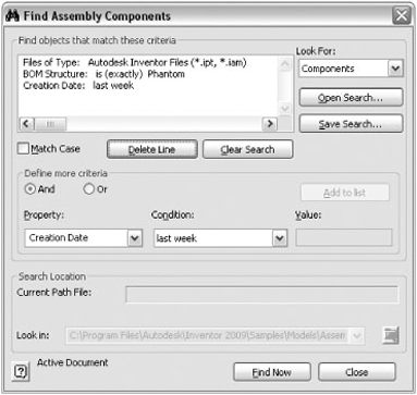
Navigating a large assembly Model Browser can be a chore. To help with this, you can employ the Find tool to define search criteria for constraints, components, features, sketches, and welds. Searches can be saved for future use and recalled as needed using the Open Search button, as shown in Figure 9.13.
You can access the Find tool in the following ways:
One of the most important aspects of working on a large assembly file is being able to open the file. Although this seems an obvious statement, many Inventor users seem to approach opening a model as an afterthought. Consider it in this way—if you were tasked with carrying a pile of stones up a flight of stairs, you would probably be unlikely to attempt to carry them all up the stairs at once. But this is exactly the kind of heavy lifting you are asking your workstation to do when opening a large assembly.
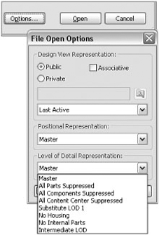
To allow your workstation to make multiple trips when opening an assembly file, you will use LOD representations. You create LOD representations by suppressing components in an assembly. Once the LOD is created, you can access it the next time you begin to open the file by using the Options button, as shown in Figure 9.14. Once the assembly file is open, you can unsuppress components as required, and those components will then be loaded into memory. You can also specify a default LOD so that the assembly opens to it without having to use the options dialog box every time. This is done from Application Options on the Assembly tab. You'll learn more about creating LODs later in this chapter.
Not only do large assembly files require some forethought and management, but so do the drawing files of these large assemblies. Because Inventor generates the line work from the models that you create views from automatically, it is easy take the large number of calculations required to do this for granted. Stop for a moment and consider all the hidden lines, sectioned parts, and so on, which Inventor has to consider in order to render your drawing views accurately.
It is for this reason that you will want to adopt slightly differently techniques than those you use to make part or small assembly drawings.
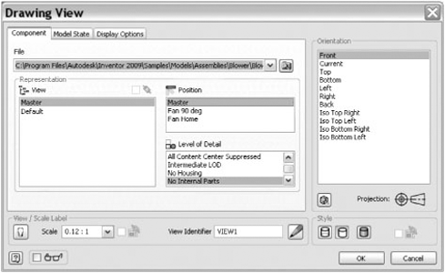
When creating drawing of large assemblies, it is advised that you do so from an LOD representation already created in the model. Doing so reduces the number of files Inventor is required to access to create and update the line work in the view. To create views from assembly representations, you simply specify the representation(s) you want to use in the Drawing View dialog box, as shown in Figure 9.15. Keep in mind that when browsing for the file to create a view of, if you use the Options button in the Open dialog box to specify the representation, you will reduce the time it takes to create the view.
Reducing Hidden Lines
Hidden line generation can be one of the most memory-intensive aspects of creating a drawing view. Generally, with large assemblies, it is not desirable to show the hidden lines of all components. Instead, you typically will want to enable hidden lines for just those components where hidden lines add clarity.
Rather than selecting the Hidden Line style in the Drawing View dialog box, first create the view with no hidden lines. Next locate and expand the view you just created in the browser, and select the components you intend to be shown with hidden lines. Right-click the components, and choose Hidden Lines.
You will be prompted with a message box informing you that you are changing the view style to show hidden lines and that any children of this view will be granted an independent view style based upon their current setting, as shown in Figure 9.16. The result will be that only the components you chose will be displayed with hidden lines.
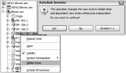
Figure 9.16. Managing hidden lines
A sure way to slow down your drawing's performance is to create an unnecessarily complex title block. If you have included a bitmap of your company logo in your title bock, ensure that the bitmap file is reduced in resolution and file size as much as possible. You can use any photo editor to do this.
Once you've reduced the bitmap file as much as possible, consider embedding the file into the title block rather than linking it. Although linking the bitmap does give you greater flexibility in updating the logo independent of the title block, Inventor will be required to locate the bitmap each time the drawing is loaded. To embed rather than link the logo bitmap, simply deselect the Link check box when inserting the bitmap.
If you have pasted the logo in from AutoCAD, ensure that the logo is as clean as possible. You may be better off removing the hatches from the logo in AutoCAD and then adding them using the Fill/Hatch Sketch Region tool in Inventor.
Although it is possible to create a large number of sheets in a single drawing file, it is generally accepted that this is not good practice. Instead, you should consider making a new file for each drawing sheet when possible. Or at the very least, keep the number of sheets per file as low as possible. There are two primary reasons for doing this.
The first reason is simply to keep the file size down. If you have a drawing of a large assembly file that includes four sheets and has a file size of 80MB, you could spilt this into two files, each with two sheets and a file size of approximately 40MB. In this way, you do not have to load the extra 40MB in sheets 3 and 4 just to make an edit to sheet 1.
The second reason to minimize drawing sheets is so you are not guilty of placing "all your eggs in one basket." Creating multiple tab or sheet files in any application can be risky. Imagine you created a load calculation spreadsheet and you developed the habit of adding a tab for each new calculation you do, rather than creating a new file for each calculation. If the file becomes corrupt, you've lost all your calculations rather than just one set of calculations. The same thing could happen with your Inventor drawing if you habitually create new sheets instead of new files.
In Chapter 8, you learned about creating LOD representations within your assemblies in order to reduce the memory requirements of working with large assemblies. Here you will consider how you can use these LOD representations to make you more successful in your large assembly pursuits.
All Inventor assemblies have four default LODs predefined and ready for you to use. Learning to use these and creating your own LODs is an important part of working with large assemblies. The default LODs are as follows:
- Master
This shows your assembly with no parts suppressed. You can think of this as the highest level of detail for any assembly.
- All Components Suppressed
This suppresses everything within the assembly. You can think of it as the lowest level of detail for any assembly.
- All Parts Suppressed
This suppresses all parts at all levels of the assembly, but subassemblies are loaded.
- All Content Center Suppressed
This suppresses any component in the assembly that is stored in the Content Center Files directory as designated by the IPJ (project) file or the Application Options settings.
When opening a large assembly, you can use the All Components Suppressed LOD to quickly open the file and then manually unsuppress components as required. However, it is more practical to create your own LODs and use them to efficiently open your assemblies. Consider creating intermediate LODs based upon your design process.
For a closer look at LODs in action, follow these steps:
From the Get Started tab choose Open.
Browse for the file named
mi_9a_002.iamlocated in the Chapter 9 directory of the Mastering Inventor 2010 folder, and click Open.Expand the Representations folder and the Level Of Detail node in the Model Browser if not already done.
Right-click the Level Of Detail header, and choose New Level Of Detail. Rename LevelofDetail1 to MediumLOD.
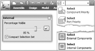
In the Quick Access toolbar, click the selection tool drop-down list (see Figure 9.17), and set your selection focus to Component Priority if it is not already.
Using the same drop-down list, now choose Internal Components, as shown in Figure 9.17.
Set the slider to 85 percent, and click the green check mark.
Right-click anywhere on the screen, and choose Isolate to get a better view of the components you selected. Your screen should look similar to Figure 9.18.
Now bring back one component to add to your selection set. Select the component called MA- 001:1 in the browser, right-click, and choose Visibility. You should see the motor subassembly become visible.
Select all the components on the screen. You can use a crossing window to do this quickly.
Right-click, and choose Suppress.
Right-click anywhere, and choose Undo Isolate to bring back the visibility of the remaining components.
Save the assembly to ensure that the changes to your newly created level of detail are recorded.
Switch back and forth between the master LOD and your MediumLOD to observe the differences.
To modify the MediumLOD, activate it and suppress any component you'd like; then save the assembly.
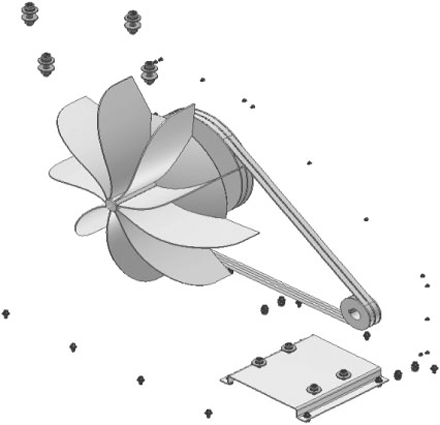
You can use substitute LOD representations to trade out a large multipart assembly with a single part derived from that assembly. Substitute LODs improve efficiency by reducing the number of files Inventor is referencing and, if created from other LODs, can also reduce the amount of geometry required.
For example, in the blower assembly, you could create a substitute LOD from the entire assembly and then place that substitute into a top-level assembly as needed. You would certainly gain some efficiency by doing this because the top-level assembly is referencing only one file. However, if you created a substitute from the MediumLOD, you would be maintaining an even higher level of performance in the top-level assembly because all the internal geometry that was suppressed in the creation of that LOD would be omitted.
To create a substitute LOD, follow these steps:
From the Get Started tab choose Open.
Browse for the file named mi_9a_003.iam located in the Chapter 9 directory of the Mastering Inventor 2010 folder, and click Open.
Expand the Representations folder and the Level of Detail node in the model browser if not already done.
Double-click the MediumLOD to set it as the active LOD if not already done.
Right-click the Level Of Detail header in the browser, and choose New Substitute and then Shrinkwrap. Notice that Inventor is asking you to specify a filename, a file template, and a location to create this file.
Enter mi_9a_003_Substitute_100 for the name in the New Derived Substitute Part dialog box, and leave the template and file location at the defaults.
Click OK. Inventor opens a new part file and takes you directly into the shrink-wrap process, bring up the Assembly Shrinkwrap Options dialog box.
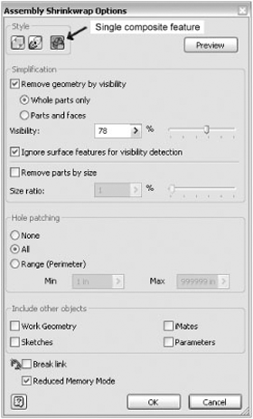
In the Style area at the top, ensure that the Single Composite Feature option is selected. The following are the descriptions of each of the three available options:
- Single Solid Body Merging Out Seams Between Planar Faces
Produces a single solid body without seams. Merged faces become a single color, where required.
- Solid Body Keep Seams Between Planar Faces
Produces a single solid body with seams. Colors are retained.
- Single Composite Feature
Produces a single surface composite feature and the smallest file. Colors and seams of the original components are maintained. The mass properties of the original assembly are stored in the file for reference.
Ensure that the Remove Geometry By Visibility check box is selected.
Select Whole Parts Only.
Play around with the slider, clicking the Preview button to see what is removed.
Set the slider to 78 percent.
Under Hole Patching, select All.
Ensure that Reduced Memory Mode is selected at the bottom of the dialog box. When selected, this option allows the derived part to be created using less memory by not including the source bodies of the assembly parts.
Refer to Figure 9.19 to check the settings, and then click OK.
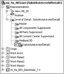
Click Yes when asked about the mass properties. Note that Inventor closes the derived part file and returns to the assembly, and an LOD named SubstituteLevelofDetail1 has been created. You can rename this if you like by clicking it once and then a second time.
Save the assembly.
Double-click the MediumLOD to set it active, and compare the substitute LOD by clicking back and forth on them.
To see that the substitute shrink-wrap is a surface model, click the View tab, and choose the Half Section View icon from the drop-down list on the Appearance panel.
Click Workplane2 in the Model Browser.
Right-click, and choose Done.
Choose End Section View from the drop-down list on the Appearance panel to turn off the section view.
Figure 9.20 shows the Substitute LOD as it appears in the browser.
Recall that all LODs maintain an accurate BOM listing. To confirm this, select the Assemble tab, click Bill Of Materials, and interrogate the BOM to see that even though the substitute LOD consists of a single part, Inventor still maintains the BOM information for the entire assembly.
Subassembly use is where LOD representations really begin to pay off in terms of performance. Once LOD representations have been created in your assembly, you can switch the LOD in the subassemblies to match in three ways:
Place the subassemblies into a top-level assembly with the matching LOD by using the Options button.
Switch the LOD manually in the subassembly in the Model Browser.
Use the Link Levels Of Detail tool at the top-level assembly to automatically set the subassemblies to the matching LOD.
In Figure 9.21, all the subassemblies have LODs named High, Moderate, and Low set up within them. Then the LODs were linked. The LOD name is set in parentheses next to the assembly name.
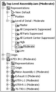
You might take this concept one step further and edit your assembly templates to automatically have High, Moderate, and Low LODs already in them. This way you do not have to create the LODs, but instead you can simply activate them and then suppress parts as required to "fill them out."
Recall that Inventor specifies your template location on the File tab of the Application Options dialog box. Note that this can be overridden in your project file. Check this by selecting the Get Started tab and then clicking the Projects button, and look in the Folder Options section of the Project File Editor that opens. If a path is specified there, that is where your templates are located. If it shows = Default, then the path found in Application Options is where your templates are located.
In the following exercise, the subassemblies all have LODs created in them. These are called Bolts, Washers, Nuts, and Galvanized. Each subassembly was configured with these LODs set up as described in the previous exercise. The top-level assembly has three LODs created called Bolts, Washers, and Nuts. Although these LODs have been created, they have not been configured and currently do not differ from the master LOD. The following steps take you through the linking of the Bolt LOD at the top-level assembly to the Bolt LODs in the subassemblies:
From the Get Started tab choose Open.
Browse for the file named
mi_9a_004.iamlocated in the Chapter 9 directory of the Mastering Inventor 2010 folder, and click Open.Expand the Representations folder and the Level Of Detail node in the Model Browser if it is not already expanded.
Double-click the LOD named Bolts to set it active, or right-click it and choose Activate.
Click the Assemble tab, expand the drop-down list for the Productivity panel, and choose Link Levels Of Detail.
Click Bolts within the Link Levels Of Detail dialog box.
Click OK in the Link Levels Of Detail dialog box, and click OK to accept the warning that the assembly will be saved.
Note the subassemblies have all been set so that the Bolts LOD is active in them. If one of the subassemblies did not have an LOD called Bolts, it would be left at its current LOD. You can continue this exercise by repeating these steps for the Washers and Nuts LODs if you'd like. Note too that each of the subassemblies has an LOD called Galvanized in which all parts that are not galvanized steel have been suppressed. You can create an LOD in the top-level assembly called Galvanized and then use the Link LODs tool to suppress all the parts not made of galvanized steel.
Albert Einstein once suggested that things be made as simple as possible but not simpler. This is a good concept to keep in mind when creating models in Inventor. Adding extraneous details to common parts can have a negative impact on large assembly performance. Of course, if the part file is to be used for fabrication, then a certain level of detail is required. Oftentimes, though, we create models of common parts to be used in an assembly for the end goal of getting an accurate bill of materials. Your assembly performance could most likely be improved by reducing the amount of detail in those types of parts.
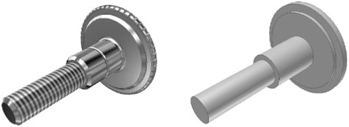
Reducing the number of edges and faces in a part is a sure way to minimize the size of the part file. Removing fillet and chamfers for purchased parts is good way to eliminate extra faces. If you have common parts that are used in large numbers throughout your assemblies, you might consider creating two versions of these parts: one version for use in large assemblies and another from which you create production drawings and Inventor Studio renderings. In Figure 9.22, you can see two versions of the same part. The file on the left is right at 600KB, whereas the one the right is less than 175KB.
In the following steps, you will derive a simplified version of a part and set the part numbers to match so that the two files report the same in the BOM and parts lists. To create a simplified part, follow these steps:
From the Get Started tab choose Open.
Browse for the file named
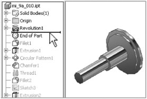
mi_9a_010.iptlocated in the Chapter 9 directory of the Mastering Inventor 2010 folder, and click Open.Click the end-of-part (EOP) marker in the Model Browser, and drag it to right under Revolution1.
Change the color to As Material (at the top of the screen in the Quick Access toolbar, click the color drop-down arrow, and scroll to the top).
Do not save the part.
Figure 9.23 shows the end-of-part marker being placed above the existing features.
From the Get Started tab choose New.
Choose the
Standard.ipttemplate to create the new file, and click OK.In the new part, right-click and choose Finish Sketch.
On the Manage tab, click the Derive icon on the Insert panel.
In the resulting Open dialog box, browse for the file named
mi_9a_010.iptlocated in the Chapter 9 directory of the Mastering Inventor 2010 folder, and click Open.Choose Maintain Each Solid As A Solid Body as the derive style.
Click OK.
In the Model Browser, right-click the part name, and choose Suppress Link With Base Component. This ensures that the derived part will stay at the simplified state.
Click the filename at the top of the Model Browser, and choose iProperties.
Choose the Project tab of the iProperties dialog box, and enter mi_9a_010 as the part number. This ensures that as you use the simplified part in an assembly it will have the same part number as the original part and report an accurate BOM.
Save the file as
mi_9a_010_simple.ipt.Either close the file and click No when asked to save changes, or drag the EOP marker back to the bottom of the Model Browser and reset the part color and then save the file.
The result is two files representing the same part. Both will list at the same component in the BOM, but the derived component will add far less overhead when used over and over in an assembly.
Adding a reflective color to a part can increase the file size as well; therefore, you should consider using a flat color for simplified parts you intend to use over and over again in large assemblies. It is good practice to purge all unused color style definitions for common parts as well. Each time you change a material or color in a part file, the style definitions are cached in the file. If the file is used many times in an assembly, the unused definitions can have an impact on memory. To purge unused style definitions, select the Manage tab and click the Purge button found on the Styles and Standards panel.
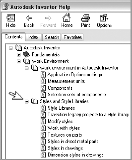
Using Style Libraries
If you have not looked at using style libraries to manage your material, color, and lighting style definitions, then you should take the time to do so. Style libraries are not always the right choice for every design office, but if you determine that they are, you can speed up the processing of your files considerably. To determine whether this is the right choice for you, go to the help files as shown here.
- Select a workstation
Having the right tool for the job is the key to success in anything you do. This is true of selecting a large assembly workstation. You have learned that for optimal performance you should strive to keep your system working in physical memory (RAM).
- Master It
You notice that your computer runs slowly when working with large assemblies and want to know whether you should consider a 64-bit system.
- Adjust your performance settings
You have learned that there are many settings in Inventor and in Windows that you can use to configure the application to work more efficiently with large assemblies.
- Master It
You want to make your current workstation run as efficiently as possible for large assembly design.
- Use best practices for large assembly
Knowing the tools for general assembly design is only half of the battle when it comes to conquering large assemblies. Understanding the methods of large assembly design and how they differ from a general assembly design is a key to success.
- Master It
You want to create adaptive parts so that you can make changes during the initial design stage and have several parts update automatically as you work through the details. But you are concerned about how this will adversely affect your assembly performance.
- Manage assembly detail
Inventor includes several tools to help manage assembly detail so that you can accomplish your large assembly design goals.
- Master It
You want to reduce the number of files your large assembly is required to reference while you are working on it and yet maintain an accurate bill of materials.
- Simplify parts
Creating highly detailed parts may be required for generating production drawings or Inventor Studio renderings, but using those high-detail parts in large assemblies may have an adverse affect.
- Master It
You want to create a lower level of detail part file for common parts to be reused many times over in your large assemblies but are concerned about managing two versions of a part.