
Developing a good assembly design workflow is paramount to achieving performance, flexibility, and stability in your designs. In this chapter, you'll explore several types of workflows to achieve that goal.
Included in this chapter is a discussion on how to use subassemblies to enhance performance. Using subassemblies within your design can substantially improve performance and ease of constraining.
Large assembly design is an achievable goal with Inventor. Inventor removes the limitations of memory with a true 64-bit version. If you run the 64-bit version on Windows XP 64 or Windows Vista, your hardware is the limiting factor for RAM instead of the OS. Component count can now be in the hundreds of thousands of parts, as long as you have sufficient memory on your system.
Performance in large assembly design assumes that you understand the principles and proper use of subassemblies and the role that adaptivity plays in performance. Armed with that understanding, you can configure your system for performance and develop a good workflow that allows you to design large assemblies without suffering slow system performance.
In this chapter, you'll learn to:
Organize designs using structured subassemblies
Use positional reps and flexible assemblies together
Copy designs
Substitute a single part for entire subassemblies
As you will see in this chapter, you create assemblies by placing 3D constraints between parts in order to position and hold those parts together. When working with small assemblies, you can often assemble all the parts together at one level. Working with larger assemblies, however, often requires the use of multiple levels of assemblies for the sake of organization and performance. Lower-level assemblies are referred to as subassemblies.
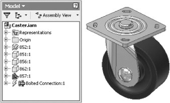
Imagine a common caster wheel assembly. Although it may seem like a simple component, it is of course made up of many small parts. If you needed to use this caster in an assembly multiple times, you wouldn't place all the small parts into an assembly individually over and over. Instead, you would package them as a subassembly and place multiple instances of the subassembly throughout the top-level assembly. Figure 8.1 shows a caster wheel assembly ready to be placed as a subassembly.
Most things that you design and build are typically made from subassemblies of some sort. In manufacturing it makes sense to create subassemblies of common parts to make the assembly process easier. It makes sense to design in exactly the same fashion. In the caster example, it saves you from having to duplicate the work of assembling the caster parts repeatedly for each instance of the caster that exists in the top-level assembly.
A second benefit to using subassemblies is the flexibility that they add to the bill of materials. Using the caster as a subassembly rather than as loose parts provides the ability to count the caster as a single item, to count the total of all the caster parts, or to do both.
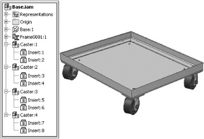
There is a third and very important concept to consider when working with subassemblies. This is model performance. Imagine that you decided to place four instances of the caster into an assembly as loose parts rather than as a subassembly. For the sake of simplicity, say it takes 28 constraints among the caster parts and 2 constraints between the caster and the top-level assembly, for a total of 30 constraints. You do this for all 4 casters, for a total of 120 constraints in the top-level assembly. Had you assembled the caster as a subassembly and then placed that subassembly into the top-level assembly, you would have used just 28 in the caster subassembly and 2 per caster, for a total of only 36 constraints, as shown in Figure 8.2.
If you consider assembly constraints to be nothing more than calculations that Inventor must make to hold the assemblies together, then by using subassemblies you have required Inventor to create and maintain 86 fewer calculations overall. This reduction in constraints can have a significant impact on the assembly's performance and make the task of editing the assembly much easier.
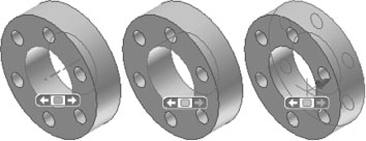
When multiple instances of the same subassembly are used within a design, each instance can be made flexible, relaxing constraints within the assembly to allow for changes in position within the top-level assembly. The caster assemblies in Figure 8.3 have been made flexible so that they can be swiveled and positioned independently as they would in the real world. Compare the caster positions in Figures 8.2 and 8.3, and you will notice that in Figure 8.2 all instances of the caster were required to maintain the same position because they had not yet been made flexible.
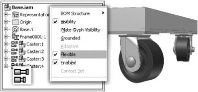
A subassembly instance is made flexible by right-clicking the instance within the browser and selecting Flexible. Flexible subassemblies are displayed with an icon next to the instance name in the browser so that you can easily determine which instances are flexible.
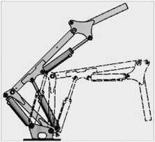
Flexible assemblies can be nested into other subassemblies and will still update whenever the original assembly is changed. Common usages of flexible assemblies are hydraulic cylinders requiring different length extensions when used in multiple locations within a top-level assembly. When each instance of the assembly is made flexible, then each cylinder can move accordingly within the top-level assembly.
If a subassembly with nested flexible subassemblies is to be placed into a top-level assembly, then you simply right-click that subassembly to bring forward the flexibility of the nested flexible assemblies. Consider the example of the hydraulic cylinder. Multiple instances of the cylinder might be placed into an extension arm assembly and each instance made flexible so that they can be allowed to adjust as they are constrained to the extension arm parts.
If two instances of the extension arm are then placed into a top-level assembly, those instances of the extension arm need to be made flexible as well in order to allow the cylinders to demonstrate flexibility.
Inventor allows you to approach the creation of parts and assemblies in three basic ways. Figure 8.4 shows these three distinctive workflows for assembly design.
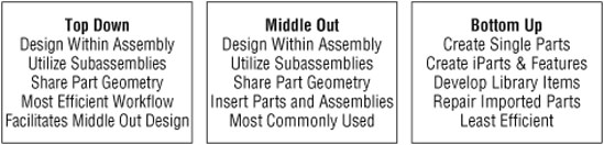
The first of these methods is called top-down design. In the purest sense, top-down design is performed completely within the top-level assembly of a machine or device. Parts and subassemblies are created from within the uppermost assembly, as opposed to creating components outside the top-level assembly and then placing these components later. Using this approach, you can reference and project geometry from other parts within the assembly into new parts, thereby ensuring the fit of the new parts. Another benefit to top-down design is that the designer can better visualize how each part relates to others within the assembly. When properly utilized, you minimize the number of overall assembly constraints required and allow for a stable design.
The second method works by creating parts independently and then placing and constraining them into the assembly. This method is called bottom-up design. Bottom-up design is common when creating parts from existing drawings and new pencil sketches. This workflow is ideal for repairing imported geometry, creating standard parts for your library, and converting standard parts into iParts and iFeatures. Working in the single-part environment does not easily allow you to create or reference other parts that will be utilized within your assembly design. As a result, this is probably the least efficient workflow for 3D design but is often the one employed by new users.
The third method is some combination of top-down and bottom-up design and is the most common. This approach might be called middle-out. This is top-down design with the ability to add existing subassemblies and parts as needed. Utilizing various functions such as Parts Libraries, Frame Generator, Bolted Connections, and Content Center components within an assembly file are examples of middle-out design.
Let's consider an example of a top-down workflow to better understand the benefits and efficiency of this type of design. Within this workflow, you will first create the top-level assembly file and then create the part files:
On the Get Started tab, click the New button, and select the
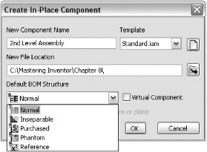
Standard.iamtemplate.Click Create on the Assemble tab, or right-click in the browser or graphics area and select Create Component. The default option in the Create In-Place Component dialog box is to create a new component as a standard single-part file. Instead, click the drop-down arrow in the Template area, and select
Standard.iam.Name this assembly 2nd Level Assembly.
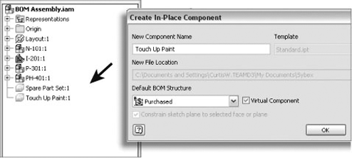
If known at the time of creating the subassembly file, determine the BOM structure for this subassembly. Note that you can change this later as needed. Figure 8.5 illustrates the selection choices for the BOM structure.
The choices for BOM structure are listed here with a brief description. You'll take a more in-depth look at BOM structure settings later in this chapter.
- Virtual Components
These components require no geometry, such as paint, grease, and so on.
- Normal
This is the default structure for all parts that are intended to be fabricated.
- Purchased
These are parts or assemblies that are not fabricated in-house.
- Inseparable
Generally, these are assemblies that cannot be disassembled without damage, such as weldments, riveted assemblies, and so on.
- Phantom
Typically, this is a subassembly created to simplify the design process by reducing assembly constraints and to roll parts up into the next highest assembly level.
- Reference
This is used for construction geometry or to add detail and references to the top-level assembly.
In this top-down design example, you will be using Normal components. Confirm the Default BOM Structure is set to Normal, and click OK.
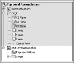
You will then be prompted to select a sketch plane for the base component of this assembly. In the Model browser, expand the assembly origin folder, and select the XY Plane option.
This will place and anchor the new assembly to the top-level assembly origin. The origin planes of the new assembly will be anchored to the selected top-level assembly origin plane upon creation and will be grounded to the top-level origin plane. This new, second-level assembly will be activated within the Model browser, ready for editing, as shown in Figure 8.6.
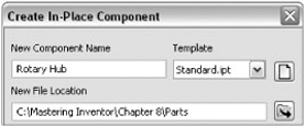
With the second-level assembly active, select Create Component once again, and this time use the
Standard.ipttemplate to create a new part. Name this component Rotary Hub, and locate it in a subdirectory called Parts within your workspace, as shown in Figure 8.7. If the subdirectory does not exist, you will be prompted to create it. Use the Normal BOM structure for all parts in this example.To place the part, select the XZ plane from the origin folder in
2nd Level Assembly.iam, and click the XZ plane.Because the XZ plane is perpendicular to the screen, you will need to realign the view to the current sketch plane. Click the View Face button on the Navigation bar, and click Sketch1 in the Model browser. When clicking this icon, you will notice that Sketch1 is active and everything else within your assembly is grayed out. You should now be properly oriented to view Sketch1.
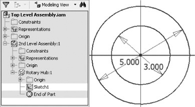
Create and dimension the sketch, as shown in Figure 8.8.
Press E to display the Extrude dialog box, and extrude the outer ring to a length of 1 inch.
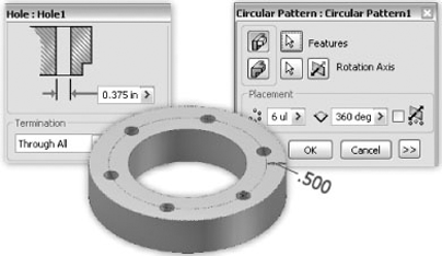
Create a sketch on the top face of the ring. Sketch a concentric circle offset 0.5 inch to the inside of the overall diameter. Place a center point on the offset circle.
Start the Hole tool. The center point will be automatically selected. Set the diameter to 0.375 inch, and set Termination to Through All.
Create a circular pattern of the hole feature with six instances, as shown in Figure 8.9.
Click the Save icon. Since the part is active, it is saved, but the top- and second-level assemblies are not. Click the Return button twice to return to the top-level assembly.
Click Save again, and you will be prompted to name the top-level assembly file. Name the file Top Level Assembly, and click OK.
The Save dialog displays the state of all the assembly files. Both of the assembly files are marked Initial Save. This means that they exist only in memory and haven't been saved to disc yet. If you were to click in the Save column to change it to No, the files would be closed without saving, and you would just have the part file. Confirm that the both files are marked Yes, and click OK.
Inventor 2010 includes new functionality that supports top-down and middle-out design workflows. Layout sketches enable you to separate form and function. The first step is creating a layout sketch for the assembly. Next, 2D sketch geometry and sketch blocks are used to represent components. Once the basic design is complete, you use Make Part and Make Component to create the models from the sketch blocks. The models are linked to the sketch blocks, so if you update the layout, the parts and assemblies will automatically update.
The following example will introduce layout and sketch block functionality:
Switch to the Get Started tab, and click Open.
Browse to Chapter 8 in the Mastering Inventor 2010 directory, and open
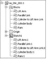
mi_08a_001.iam.Right-click
mi_008a_001:1in the browser, and select Expand All Children. Note that there is a Blocks folder, and it contains the same blocks as Sketch1, as shown in Figure 8.10.Click Create Block on the Layout panel of the Sketch tab.
Select the three yellow sketch lines.
Change Block Name to Jack Plate.
Click OK. Note that Jack Plate is added to both the Blocks folder and Sketch1.
Click and drag the horizontal yellow line in the Jack Plate block. This simulates the motion of the jack.
Click Make Components on the Layout panel of the Sketch tab.
Select all of the blocks. Click Next, and make note of the filenames.
Click OK. A part is created for each block.
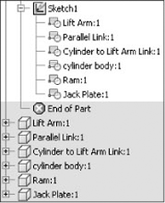
The parts have the same name as the blocks, as shown in Figure 8.11. This makes it important to use descriptive names for the blocks instead of accepting the defaults.
Layout sketches can boost your productivity. During the initial stage of design, there are frequent changes as you nail down the details. When you initially create the layout sketch, you can easily investigate "what if?" scenarios. You can add as much or as little detail as you need to define the function and form. If you do need to make a change in the relationship of components, you can do that in the layout sketch, and then the update will get pushed to all the components. Once components are generated from the blocks, you can edit them and build the model parts based on the basic blocks.
Cross-part adaptivity is a powerful feature of Autodesk Inventor. Unlike some other 3D modelers, creating relationships between parts in an assembly is a simple task. In Inventor, you can turn adaptivity on or off at will. Other modelers may require that the relationships be deleted in order to turn off an adaptive feature.
Although adaptivity is a powerful tool when properly used in Autodesk Inventor, it can cause performance problems when used indiscriminately in large assemblies or when an adaptive part is utilized in another assembly without its related part. But you can fix both situations with very simple methods.
Active adaptive parts can cause performance issues in large assemblies. As a result, you should turn off adaptivity after use. If a related part is edited, adaptivity on the associated part should be turned on, and the assembly should be updated to reflect the changes on the related part. Once this is done, that adaptivity should be turned off once again.
If an adaptive part is to be used in other designs, then it is suggested that you save the part as a different filename and remove the adaptivity from the new part. Otherwise, the adaptive relationships will carry over into the other design, preventing the ability of shared parts to be edited.
This example creates an adaptive relationship between two parts and demonstrates how they are linked together:
On the Get Started tab, click Open.
Browse to Chapter 8 in the Mastering Inventor 2010 directory, and open
mi_08b_001.iam.Double-click
mi_08b_002:1in the browser to edit it.Click Create on the Assemble tab, or right-click in the browser or graphics area and select Create Component.
Name the new part file Gasket. For the New File Location, browse to the Chapter 8 folder. Confirm that "Constrain sketch plane to selected face or plane" is selected. Click OK.
Select the top face of the part. When this face is selected, a Flush constraint is created between the two parts.
Sketch1 in the new part is automatically activated, and the existing part becomes transparent. The Component Opacity setting on the Application Options dialog box's Assembly tab controls this behavior.
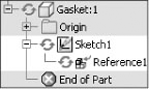
Click Project Geometry on the Sketch tab, and select the top face of the existing part. The geometry is projected into the sketch. Note that adaptive glyphs have been added to the browser to indicate that the part and sketch are adaptive. Also, there is a Reference1 node nested under the sketch. This node contains the information linking the two parts, as shown in Figure 8.12.
The adaptive glyph is displayed when adaptivity is turned on. You can turn adaptivity on and off by right-clicking the node in the browser. You can toggle the feature or sketch adaptivity while editing the part, but you have to return to the assembly level to toggle adaptivity on the part.
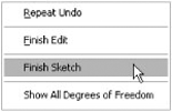
Finish the sketch by selecting Finish Sketch from the right-click menu, as shown in Figure 8.13. Do not click Finish Edit because Inventor will not only finish the sketch in that case but will also exit the part and return you to the subassembly.
Extrude the Gasket part to a thickness of 0.040 inch, click the Return icon once to move up to the second-level assembly design state, and then click Save.
To see how adaptivity works, double-click the Rotary Hub component to activate that part for editing. You can double-click the part in the graphics area or the icon next to the part name in the Model browser to activate any part for editing.
In the Model browser, right-click Extrusion1, and select Edit Sketch. Change the overall diameter from 5 to 7, and click OK.
You will notice that the overall diameter and the diameter of the hole pattern of the Rotary Hub component have changed, but the corresponding Gasket part remains unchanged.
Click Return to move up to the second-level assembly design state once again. Both parts are active at the subassembly level, so the Gasket part updates to match the Rotary Hub component.
Once a design has been approved and released for production, you should completely remove adaptivity from all parts within your assembly. Removing the adaptivity ensures that the part can be reused within other designs without conflict.
If you decide to retain adaptivity within your original assembly but plan on using the adaptive part in other assemblies, the adaptive icon will not display on those instances of the part. This is because only one occurrence of a part can define its adaptive features. However, all occurrences reflect changes and adaptive updates, including occurrence in other assemblies. It is for this reason that you must use adaptivity carefully.
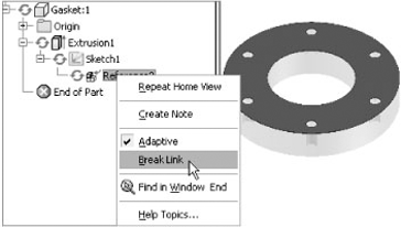
To completely remove adaptivity from a part, either activate or open the adaptive part, and activate the adaptive sketch. Expand the sketch and right-click Reference to select Break Link, as shown in Figure 8.14.
When the adaptive link is broken, the reference geometry is converted to normal sketch geometry. This geometry will need to be fully dimensioned and constrained. Once the geometry has been converted to normal sketch geometry, the part will no longer be able to be adaptive.
3D constraints are the glue and nails of construction when it comes to 3D modelers. Properly using 3D constraints will permit the construction of stable assemblies, assist in developing stack-up tolerances, and allow parts to be driven to show the animation of a process.
Improperly using 3D constraints can create a nightmare of broken and/or redundant constraints, preventing assemblies from functioning properly, destroying assembly performance, and creating rework. Understanding how 3D constraints function in an assembly will help assure success in building and editing your design.
In a 3D modeler, constraints are used to attach parts or subassemblies together, creating assembly relationships between the components. In practice, constraint function follows real-world assembly techniques where fasteners, adhesives, and welds attach one component to another.
Using the Mate constraint as an example, three Mate constraints can function like glue in the real world, permanently binding components together. The net effect within an assembly is just like glue in that if you move one component, the other component will move also. Unlike glue, however, this joint is editable at any time.
Applying one Mate constraint between two components will remove one direction in which those components can be moved freely. The result of the Mate constraint is dependent upon the geometry selected. Consider two simple blocks with a single hole in each of them. If you apply a single Mate constraint between the top face of one block and the bottom face of the second block, they would no longer be free to travel in the Z direction but would still be free to travel in the positive and negative X and Y planes. Adding a second Mate between the centerlines of the holes would reduce the ability of the parts to travel freely in the X and Y planes but would still allow the blocks to rotate around the z-axis. Another constraint could then be added to remove that rotation if required, or it could be left unconstrained if that were the intent of the design.
Some 3D constraints permit the use of an offset distance to separate two components by a specified amount. This allows the precise control of clearance between parts.
Motion constraints create rotational relationships between parts, allowing the simulation of geared or driven movement. Transitional constraints can allow one component to move along an exact path, maintaining a perfect alignment relationship to the path.
When using 3D constraints, remember that a minimum of two and a maximum of three constraints are required to fully constrain two components together. Components fully contained within a subassembly will not figure into the constraint analysis when the top-level assembly is opened or modified.
Each unconstrained component existing within an assembly file possesses six degrees of freedom. The degrees of freedom are bidirectional and consist of three axial degrees of freedom along the x, y, and z origin axes, as well as full rotational freedom around the same axes.
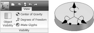
For ease of use when learning and applying 3D constraints, you may make the degrees of freedom visible through the View tab by clicking the Degrees Of Freedom button. As constraints are applied to your component, the Degrees Of Freedom icon will change to reveal the remaining degrees of freedom. When the component is fully constrained, the icon will disappear. Figure 8.15 illustrates the activation process.
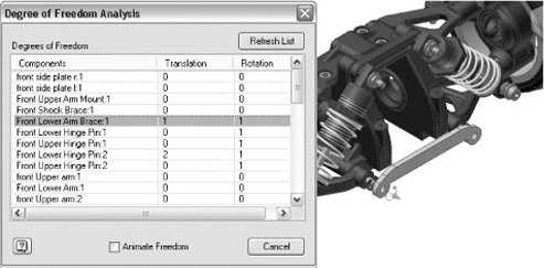
You can also analyze the degrees of freedom for the complete assembly. Degree Of Freedom Analysis is located in the Productivity panel's drop-down list on the Assembly tab of the Ribbon. A dialog box displays each component (part or subassembly) at the active level of the assembly. The number of translation and rotation degrees of freedom are listed.
If you select Animate Freedom at the bottom of the dialog box, an underconstrained component will move when you click it in the list, as shown in Figure 8.16.
Follow these steps to animate the underconstrained component:
Close any files you might have open in Inventor.
Click the Get Started tab, and click Open.
Click the Projects button to display the Projects dialog box.
Double-click the Samples project to activate it, and then click Done.
Browse to Models

On the Assemble tab, click the drop-down on the Productivity panel, and select Degree of Freedom Analysis.
Click Front Lower Arm Brace:1. Watch it move in and out and then rotate. This component is underconstrained.
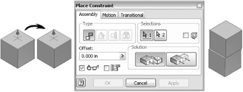
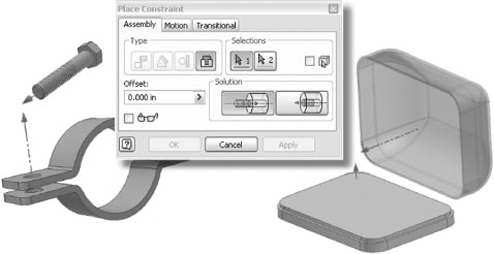
Activating the Place Constraint dialog box, you will notice that there are four basic types of assembly constraints: Mate, Angle, Tangent, and Insert. Each of these assembly constraints has more than one solution, allowing great flexibility in joining two components together.
Exploring the Mate solutions, you will see that one solution option is Mate, which permits two opposing faces to mate together, similar to joining two physical objects together. The other solution option is the Flush constraint, which allows two component faces to be made flush to each other. With either option, offset distances will affect how the two faces are positioned. Figure 8.17 shows a Mate/Mate solution with no offset.
Within the Place Constraint dialog box, you have three check boxes. First, the Pick Part First check box, indicated by the small red cube, is useful when parts are partially obscured or are positioned in such a way that clicking a face or edge is difficult. This option filters the selectable geometry to a single component.
Second, the Show Preview check box, indicated by the glasses icon, previews the constraint based upon the geometry selected once both selections are made. If the Show Preview check box is not selected, underconstrained components move into place only when the OK or Apply button is clicked. If either component is adaptive, constraints are not previewed even when the Show Preview box is checked.
Third, the Predict Offset And Orientation check box, found next to the Show Preview check box, captures the current offset location value when the object is selected. When unchecked, the offset location value is assumed to be zero.
To apply a Mate constraint between two components, select an edge, face, circular feature, or work feature on the first component. Note that you can cycle through the available selections using the Select Other tool, as shown in Figure 8.18.
Next, select the geometry on the second component to be mated. If the Show Preview box is selected, the components will move to reflect the results of your selection. If you make an incorrect selection, you can choose the selected geometry again by simply clicking the arrow buttons that correspond to selection 1 or selection 2.
Entering a value in the Offset text box will adjust the preview according to the value you specify. To preview the Flush solution, click the Flush button in the Solution area of the Place Constraint dialog box. Note that the Flush constraint requires two faces. If you selected something other than a face, that selection is cleared when you click the Flush button. To set the constraint, you can click either the OK button or the Apply button. Note that clicking Apply allows you to continue placing constraints as required, whereas clicking OK sets the constraint and exits the dialog box.
The Angle constraint permits three solutions within this constraint type. The solutions are Directed Angle, Undirected Angle, and Explicit Reference Vector. The Directed Angle solution always applies the right-hand rule, meaning that the angle rotation will function in a counterclockwise direction.
The Undirected Angle allows either counterclockwise or clockwise direction, resolving situations where a component orientation will flip during a constraint drive or drag operation.
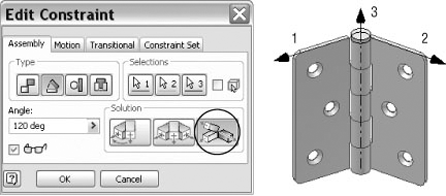
The Explicit Reference Vector solution allows for the definition of a z-axis vector by adding a third click to the selection. This option will reduce the tendency of an Angle constraint to flip to an alternate solution during a constraint drive or drag. Figure 8.19 illustrates the selections required for this solution.
You will probably find that using edges rather than faces for angle constraints will provide more predictable results, particularly when setting up constraints to be used in creating positional variations for animation or documentation purposes. The Explicit Reference Vector solution will provide you with the most predictable results because it defines the angle completely within the angle constraint, whereas the other solutions may be dependent upon other assembly constraints.
A Tangent constraint results in faces, planes, cylinders, spheres, and cones coming in contact at a point of tangency. Tangency can exist inside or outside of a curve depending on the direction of the selected surface normal. The number of degrees of freedom a Tangent constraint removes depends on the geometry. When a Tangent constraint is applied between a cylinder and a planar face, the constraint will remove one degree of linear freedom as well as one degree of rotational freedom from the set. Figure 8.20 shows the placement of a Tangent constraint.
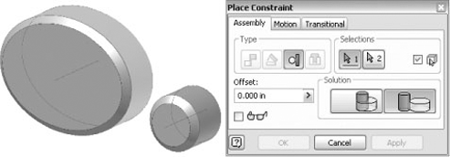
The Insert constraint is probably the best choice for inserting fasteners and other cylindrical objects into holes or for constraining any parts where circular or cylindrical geometry is to be constrained to one another. A single Insert constraint will replace two Mate constraints, retaining one rotational degree of freedom. Options for the Insert constraint are Opposed and Aligned. The Insert constraint also allows for specifying offset values between components. Figure 8.21 shows common uses of Insert constraints.
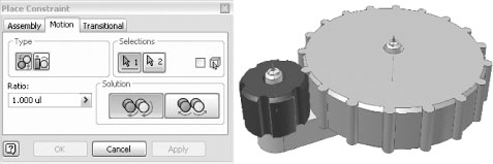
Within the Place Constraint dialog box is the Motion tab. The tab allows you to add a Rotational constraint between two components such as gears, simulating a ratio-based rotation.
To create a simple Rotational constraint, first place two components constrained around their axes. Neither component should be grounded; instead, they should be constrained to allow rotation around the axes. The Rotational constraint applies a forward or reverse solution, as shown in Figure 8.22, to the two components, along with a ratio that will determine rotation speeds.
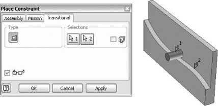
Transitional constraints allow the movement of an underconstrained component along a path in a separate part. To create a Transitional constraint, you first select a moving face on the underconstrained component. Then you select a transitional face or edge on a fully constrained or grounded part.
Figure 8.23 illustrates a pin following a spline curve acting as a guide face. To drive the pin along the path, a second Mate constraint with an offset will be applied between the origin work plane in the pin and the end of the part.
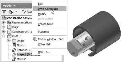
It is often desirable to simulate motion by driving a constraint through a beginning position and an ending position to confirm the intent of the design. In general, Offset and Angle constraints may be selected to drive components within an assembly. To accomplish this, simply right-click the desired constraint, and select Drive Constraint (as shown in Figure 8.24).
The Drive Constraint dialog box will appear, allowing you to alter the constraint by specifying steps between the start position and the end position. When a constraint is driven, any components constrained to the driven component will move in accordance to their particular shared constraints. The motion may be set to forward or reverse, stopped at any time, and even recorded by clicking the Record button prior to activating the move. If any of the affected components are constrained to a grounded component or if the movement will violate any existing constraint, then the drive constraint will fail.
Expanding the dialog box as shown in Figure 8.25 by pressing the >> button will reveal additional controls over the drive constraint. The increment of movement can be controlled by a value or by a total number of steps from beginning to end. The length of a particular driven constraint can be controlled by the number of allowable repetitions from Start to End or can be reversed by using the Start/End/Start option. For a continuous revolution by degrees, you may exceed 360° by specifying the total number of degrees of revolution or by including an equation such as 360 deg *3.
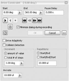
Other parts properly constrained within the driven assembly that are adaptive will adjust to changes if the Drive Adaptivity option is selected. This particular option allows determination of a maximum or minimum condition for the adaptive part.
Checking the Collision Detection option allows for determination of an exact collision distance or angle between the driven parts. Using the Collision Detection option will help you determine interferences between moving parts so that those parts can be modified before manufacturing.
Excessive constraints are considered redundant when you have overconstrained components. Redundant constraints will interfere with the proper operation of your assemblies and can cause constraint failures and performance issues.
Two toggles will assist in flagging bad constraints; you can find them by selecting Tools
Enabling Related Constraint Failure Analysis allows Inventor to perform an analysis to identify all affected constraints and components, if a particular constraint fails. Once analysis is performed, you will be able to isolate the components that use the broken constraint(s) and select a form of treatment for individual components.
Because analysis requires a separate process, performance can be affected if these two check boxes are active. Because of this, it is advisable to activate the analysis only when problems exist.
Another method for driving components within an assembly involves the Contact Solver option. With this option, only minimal constraints are required to drive a number of components. Components are not required to be constrained to one another for the Contact Solver to work.
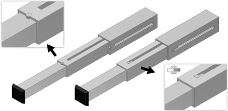
The Contact Solver works in much the same way as parts interact within the real world. Without the Contact Solver applied, moving parts can be run through one another, creating interference. With the Contact Solver applied, parts will stop when they contact one another. A simple example of this is the slide arm pictured in Figure 8.26. On the left, you can see that the arm segments have been extended past the point that they could be in reality, allowing the slide stops to run through the slide slot. On the right, the parts have been added to a contact set, and the Contact Solver has been turned on, preventing the slide stops from running through the slots.
To add parts to a contact set, simply right-click the part, and click Contact Set in the context menu. An icon will appear before each component showing when a component has been added to the contact set. In addition to adding parts to a contact set, you must also ensure that the Contact Solver is turned on by going to the Tools menu and clicking Activate Contact Solver. Once all active participants within the contact set are selected and the Contact Solver is activated, then a single driven constraint can provide a real-life simulation. Note that it is best practice to turn the Contact Solver off when performance is a consideration.
An assembly feature is a feature created and utilized purely within the active assembly file and environment. Because this feature was created within the assembly file, it does not exist at the single part or subassembly level.
A good example of an assembly feature in use is the technique of creating drilled holes through a standard tabletop within an assembly. Common practice is to place brackets on the tabletop in order to find the mounting hole locations. This allows the holes to be drilled at the same time, ensuring an exact match and placement. Assembly features in Inventor mimic this approach.
Examining the individual tabletop file reveals that the part file does not contain the drilled holes, simply because the drill operation was performed at the assembly level rather than the part level. To understand the reasoning behind this, you might consider that the tabletop is a common part stocked in the shop and then machined as required for each assembly in which it is used. Although the stock part might exist as a cataloged item with no holes, it may exist in many different assemblies with holes of various sizes and locations. Using assembly features allow you to work in this manner.
Other examples of assembly features are contained within the weldment environment, where preparations used to facilitate welding components together are at the assembly level. Preparation features allow trimming of soon-to-be-welded components to eliminate interferences between welds and other parts of the weldment.
Care must be taken when creating geometry within the context of the assembly, because it is easy to create an assembly feature when intending to create a part feature. Although this is a common mistake that new users will make, it is one that anyone can experience. In a multilevel top-down design, always make sure you are working in the proper assembly or component by double-clicking the assembly or component in the Model browser for the purposes of opening that component for editing.
Assembly features in Inventor can be created by clicking the 2D Sketch icon in the Inventor Standard toolbar located at the top of your screen. Once you click the icon, selecting any planar face within the assembly will initiate the sketch environment. Examining the browser reveals that the newly created sketch is located above the End Of Features portion of the Model browser and that all components located within the assembly are grayed out. Note that the End Of Features marker replaces the expected End Of Part marker at the end of each part feature creation or edit. In addition, the Assembly panel has replaced the 2D Sketch panel.
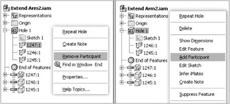
Once assembly features have been created, components can be removed from the impact of those features by expanding the assembly features in the browser, right-clicking the component, and choosing Remove Participant from the menu. Components can be added to an assembly feature by right-clicking the feature, choosing Add Participant from the menu, and then choosing the component from the browser. On the left of Figure 8.27, component 1247 is being removed from the Hole feature so that the hole does not go through the part. On the right, the same component is being added to the feature.
In addition to sketch-based assembly features, Extrudes, Revolves, Holes, Sweeps, Fillets, Chamfers, and Move Face features can be created as assembly features. Note that assembly features are allowed only to cut or remove material. Other commonly used assembly feature commands within the Assembly panel environment include the Mirror and Patterns commands.
In Inventor, the BOM is the internal, real-time database that exists within every assembly. Real-time means that as components are added to the assembly, they are automatically added and counted in the BOM. Although you might be accustomed to referring to the tabled list of parts on the 2D drawing as a bill of materials, in Inventor such a table is called a parts list. Part lists pull directly from the assembly BOM.
The BOM is controlled at two different levels: the part level and the assembly level. Both levels factor in certain aspects of how the bill of materials is generated, how components are represented, and ultimately how the parts list is generated within the drawing environment.
In the part environment, the designer has the ability to define the BOM structure of just that part. At this level, the structure can be defined as Normal, Inseparable, Purchased, Phantom, or Reference. Determining the default setting at the part level allows control of how the part is identified within the overall assembly (or assemblies) BOM. By setting the structure at the part level, you can control the assembly BOM display according to the part settings. Any structure settings at the part level can be overridden and changed to Reference at the assembly level.
Another important structure setting at the part level is the Base Quantity property. This setting controls how the part is listed in the BOM. If the Base Quantity is set to Each, the part is tallied by count. This is the default for most standard parts. The Base Quantity can also be set to reflect the value of any given model parameter. This is most often set to a length parameter so that the Base Quantity property will tally the total length of a part used in an assembly. Parts pulled from the Content Center and the Frame Generator have their Base Quantity property set to pull a length parameter by default. The Base Quantity property is set by selecting Tools
BOM control accelerates at the assembly level. You can access the Bill Of Materials dialog box by selecting the Bill Of Materials icon from the Manage panel of the Assemble tab. In the drawing environment, the BOM Editor dialog box is accessible by right-clicking the parts list and selecting Bill Of Materials.
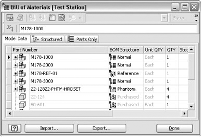
The Bill Of Materials dialog box allows you to edit iProperties, BOM properties, and the BOM structure; override quantities for components; and sort and create a consistent item order for generating parts lists. Figure 8.28 shows the Bill Of Materials dialog box.
Exporting a bill of materials is a straightforward process, with icons across the top of the dialog box allowing the export of the BOM data in a structured or parts-only view in formats such as MDB, dBase, or various Excel formats. The Engineer's Notebook icon permits the export of database information as a note.
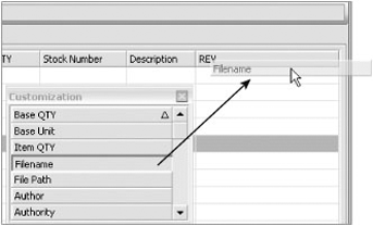
You can add columns to the model in any of the three tabs in the Bill Of Materials dialog box by clicking the Choose Columns icon, which will display a dialog box list in which you can drag a desired column to a specified location, as shown in Figure 8.29. To remove a desired column, simply drag the column to be removed back to the dialog box list.
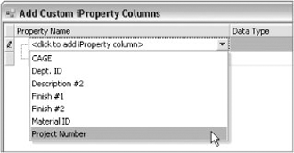
The next icon at the top of the Bill Of Materials dialog box allows you to add custom iProperty columns. The drop-down list shown in Figure 8.30 within the Add Custom iProperty Columns dialog box will display a combined list of all the available custom iProperties contained within the assembly.
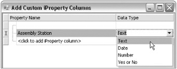
If a desired custom iProperty does not exist within the list of components, you can add it manually by selecting the <Click To Add iProperty Column> option displayed in the list box. Be sure to set the data type to the correct format when manually adding a custom iProperty to the assembly file. Manually added iProperties will be stored in the assembly file. Figure 8.31 shows the addition of a custom iProperty column called Assembly Station.
Once custom iProperty columns have been added to the assembly bill of materials, individual parts can be populated with custom iProperties as needed. Individual parts that already contain those iProperties will show the values within the respective row and column. iProperties that are edited or added to a respective part row will be pushed down to the part level; therefore, filling out iProperties at the assembly level is often the most efficient way to populate part iProperties.
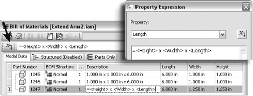
The Create Expression icon located at the beginning of the Formula toolbar launches the Property Expression dialog box so you can create an iProperty expression. The newly created expression can contain a combination of custom text and iProperty names in brackets. The iProperty expression will be substituted for the field in which the expression was created, once the expression is evaluated. In Figure 8.32, the expression is created in the Description field.
Looking across the top of the Bill Of Materials dialog box, the two icons to the far right are Part Number Merge Settings and Update Mass Properties Of All Rows. The Update Mass Properties Of All Rows icon recalculates the total mass for all components within the assembly.
Clicking the Part Number Merge Settings icon will allow different components possessing the same part number to be treated as the same component. For instance, say six base plates of the same size are used in an assembly. Four of these plates have holes drilled upon installation, and two have holes placed during fabrication. As far as the shop is concerned, all six are the same part, but in the design both plate types exist as separate part files.
To have the BOM count the total number of plates, you set the Part Number property to match on both items and then use the Part Number Merge Settings to have these files counted as a single item.
You can choose from five designations when assigning BOM structure to components: Normal, Inseparable, Purchased, Phantom, and Reference. Any part or assembly file can be assigned one of these designations within the BOM. That designation is then stored in the file, meaning that if a part is marked as Purchased in one assembly, it will be designated as Purchased in all assemblies. The structure designations are as follows:
- Normal
This is the default structure for most components. The placement and participation in the assembly bill of materials are determined by the parent assembly. In the previous example, you are creating an assembly file rather than a single part. As a result, you will be determining the characteristics of how this assembly file will behave in the top-level assembly bill of materials. With a Normal BOM structure, this assembly will be numbered and included in quantity calculations within the top-level assembly.
- Inseparable
These are generally assemblies that cannot be disassembled without damage. Examples of inseparable assemblies might include weldments, glued constructions, and riveted assemblies. In a parts-only parts list, these assemblies will be treated as a single part. Another example is a purchased part such as a motor.
- Purchased
This designation is typically for parts or assemblies that are not fabricated in-house. Examples of purchased components are motors, brake calipers, programmable controllers, hinges, and the like. A purchased component is considered as a single BOM item, regardless of whether it is a part or a subassembly. Within a purchased assembly, all child parts are excluded from the BOM and quantity calculations.
- Phantom
Use Phantom components to simplify the design process. A Phantom component exists within the design but is not shown as a line item in the BOM. A common use for a Phantom component would be a subassembly of parts that are grouped for ease of design. Setting the subassembly to be a Phantom component allows the parts to be listed in the BOM individually. Other examples of Phantom components could include hardware sets, screws, nuts, bolts, washers, pins, and various fastener-type components. A good example of a Phantom assembly would be a collection of parts that are normally assembled onto the machine one at a time. However, in the interest of reducing the overall number of assembly constraints within the design, the engineer might choose to preassemble the various components within a Phantom assembly. That assembly could then be constrained as one component instead of multiple parts.
- Reference
Mark components as Reference when they are used for construction geometry or to add detail and references to the top-level assembly. A good example of a Reference component is a car body and frame that represents the outer shell for placement of a power train. In the 2D documentation, the car body and frame would be shown as hidden lines illustrating the overall design while highlighting the power train as the principal component within a view. Reference geometry is excluded from quantity, mass, or volume calculations regardless of their own internal BOM structure. As a result, they are not included within the parts list. They are placed only within the overall assembly to show design intent and position.
In addition to these five BOM structure designations for component files, you also have the ability to create a virtual component, which has no geometry and does not exist as an external file. A virtual component can have a complete set of properties that are similar to real components but are primarily used to represent bulk items such as fasteners, assembly kits, paint, grease, adhesive, plating, or other items that do not require creating an actual model. A virtual component can be designated as any of the previous BOM structure types and can contain custom properties, descriptions, and other aspects of the BOM data like any other component.
A virtual component will be shown in the Model browser as if it were a real part. Virtual components can be created by selecting the check box next to the BOM Structure drop-down in the Create In-Place Component dialog box, as shown in Figure 8.33.
Each tab in the Bill Of Materials dialog box represents a different BOM view. All tabs permit ascending or descending sorting of the rows in the BOM by clicking the respective column header. You can also reorder rows by simply clicking and dragging a component's icon.
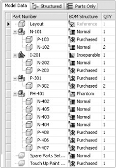
With the Model Data tab active, you see the components listed just as they exist in the Model browser. You can add or remove columns to populate the Model Data tab independently of the other BOM view tabs. On this tab all components are listed in the BOM, regardless of BOM structure designation. Item numbers are not assigned on the Model Data tab. The model data is not exportable or available for placement as a parts list. Instead, this tab is typically used for organizing the BOM and assigning the BOM structure designation.
Figure 8.34 shows a bill of materials on the Model Data tab. Notice that there are no item numbers listed and that all component structure types are displayed, including Reference and Phantom components. Notice too that the last two parts listed are virtual parts and have been given different BOM structure designations.
In addition to the Model Data tab are the Structured and Parts Only tabs. These tabs are disabled by default. To enable them, right-click the tab, and choose Enable BOM View; alternatively, click the View Options button along the top of the Bill Of Materials dialog box.
The Structured tab can display all components of the assembly, including subassemblies and the parts of the subassemblies. When in structured view, additional icons will be active on the toolbar, allowing you to sort by item and renumber items within the assembly BOM. The order of the BOM item numbers is stored in the assembly file.
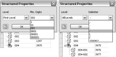
The View Options icon allows you to enable or disable the BOM view and set the view properties from the dropdown. Choose View Properties to modify the Structured view. The resulting Structured Properties dialog box contains two drop-down lists defining the level, the minimum number of digits, and the assembly part delimiter value. If the level is set to First Level, subassemblies are listed without listing the components contained within. If set to All Levels, each part is listed in an indented manner under the subassembly, as shown in Figure 8.35.
The Parts Only tab lists all components in a flat list. In this BOM view, subassemblies designated as Normal are not listed as an item, but all their child components are displayed. By contrast, Inseparable and Purchased subassemblies are displayed as items, but their child components are not displayed.
Bill of materials settings that are modified by the Bill Of Materials dialog box will carry forward into the drawing parts lists contained in the assembly. Note that if both the Structured and Parts Only views of the BOM are enabled, the same part may have a different item number in each view.
Figure 8.36 shows a bill of materials in the Structured view compared to the same assembly in the Model Data view. The first thing to note is that all the components have been assigned item numbers in the Structured view. You might also notice that the Reference and Phantom components that are listed in the Model Data view are filtered out of the Structured view. Closer inspection reveals that although the Phantom subassembly named PH-401 is not included in the Structured view, all of its child parts (N-402 through P-407) are listed, each with an arrow next to the icon to denote that they are part of a subassembly. Recall that Phantom subassemblies are used to group parts for design organization and to reduce assembly constraints while allowing the parts to be listed individually.
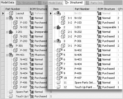
Figure 8.37 shows a bill of materials in the Parts Only view. This Parts Only view filters out Reference and Phantom components just as the Structured view does. Notice too that although the subassemblies are not listed as items, their child parts are. The exceptions to this are Purchased and Inseparable assemblies. In the figure, the Purchased subassembly lists as a single item, since it is a Purchased component comprised of two Purchased parts and is assumed to be purchased as one item. Note that if you had the need to list the parts as items rather than the subassembly, you would designate the subassembly as Phantom rather than Purchased.
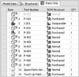
Take a look also at the Inseparable subassembly named I-201. It lists as an item along with one of its child parts named P-203. This child part lists because it is a Purchased item and needs to be ordered. Had both children of the Inseparable subassembly been Normal parts, neither would list in the Parts Only view.
Quite frequently, existing assemblies are used in other designs or are used in multiple locations within the top-level assembly. There are three basic workflows for reusing assemblies in design:
Quite often you'll need to copy a previous design in order to create a similar design based on the original. Part of the challenge of doing this with Inventor is creating copies of only the parts that will be modified in the new design while reusing parts that do not incur changes, all while maintaining healthy file links. To do this effectively, you can employ the Copy Components tool from within the assembly to be copied.
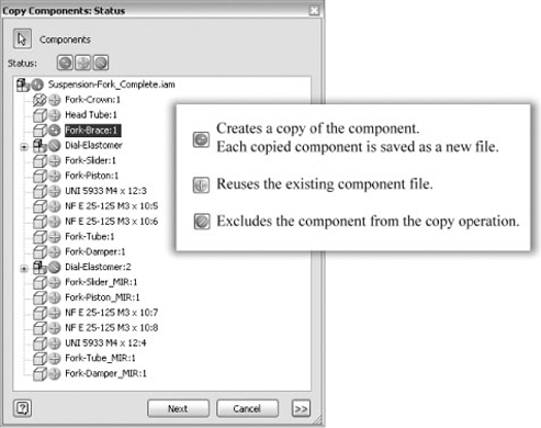
To begin this process, first select the top-level assembly from the browser tree, and then click the Copy Components button in the tool panel. You will be presented with the Copy Components: Status dialog box, which lists the top-level assembly and the components within, as shown in Figure 8.38. Use the Status buttons next to each component to set the component to be copied, reused, or excluded from the copy operation.
In the example in Figure 8.38, the Fork-Brace is the only part that needs to be redesigned for the new assembly; therefore, it is the only part set to be copied. In the original design, there are two instances of a subassembly called Dial-Elastomer. You can see that both instances have been excluded in this copy operation because they will be swapped out for another dial assembly that you have on file already. You will notice that all other components except the top-level assembly are set to be reused. Once the copy status of each part is set, click the Next button to move to the Copy Components: File Names dialog box, as shown in Figure 8.39.
In the Copy Components: File Names dialog box, you want to set the destination button to Open In New Window in order to create a new, separate assembly file. You can then use the Prefix and/or Suffix controls to modify the existing filenames, or you can type in new names as required. By default, the File Location is set to Source Path, meaning that the new files will land right next to the existing ones. If that is not desirable, you can right-click each File Location cell and choose User Path or Workspace. Care should be taken to ensure that file location paths are not set outside the project search path. When the filename and paths are set, click OK.
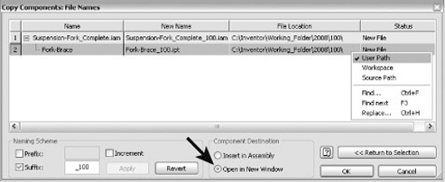
The new assembly file will open in a separate window. Interrogation of the Model browser should reveal that the components set to be reused are listed just as they were in the original assembly, the components set to be copied are listed as specified, and the components set to be excluded are not present at all.
Inventor provides the ability to create and store three basic types of representations within an assembly file. Representations allow you to manage assemblies by setting up varying views, positions, and levels of detail for your models. Each of these allows for the creation of user-defined representations, and each has a master representation. Note that although user-defined representations can be renamed and deleted as required, master representations cannot. Using representations enhances productivity and improves performance in large assembly design.
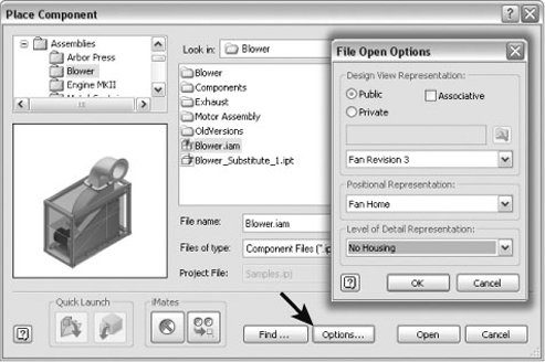
Once representations are created in an assembly, that assembly file can be opened in any combination of those representation states by clicking the Options button in the Open File or Place Component dialog box, as shown in Figure 8.40. Keep in mind that although you can open or place a file by typing the filename rather than scrolling and clicking the icon, you cannot access the Options button without explicitly scrolling and selecting the file in the dialog box.
View representations, also known as design views and ViewReps, are used to configure the display of an assembly and save that display for later use. View representations control the visibility state of components, sketch features, and work features. Also controlled by view representations are component color and styles applied at the assembly level. The enabled/not enabled status of components can be controlled in a view representation as well. In addition to these component properties, a view representation controls the on-screen zoom magnification and orientation. In effect, view representations allow "snapshot views" of portions of an assembly file. Each view representation is saved within the assembly file and has no effect on individual parts or subassemblies.
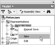
View representations are relatively simple to create and use. While in the assembly, simply zoom and rotate your model until you have the desired view showing in the current graphics window. Then, expand the Representations folder, and right-click View to select New, as shown in Figure 8.41. Now, turn off the visibility of a few parts; these visibility changes will take place only within this view representation.
After creating the new view representation, click Save to preserve the newly created representation. You can protect the view representation you create from accidental edits by right-clicking it and choosing Lock. View representations can be accessed either by double-clicking the desired representation or by right-clicking the desired representation and selecting Activate. Private view representations are views created in early releases of Inventor and are not associative.
Positional representations, often referred to as PosReps for short, can be employed to set up and store components in various arrangements and are used to help test and analyze assembly motion. Positional representations work by overriding assembly constraints, assembly patterns, or component properties.
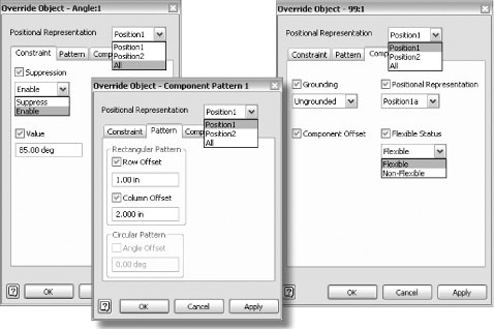
To create a new positional representation, expand the Representations heading in the browser, right-click the Positional Representations heading, and then choose New. Continue by right-clicking the component, pattern, or constraint in the Model browser that you want to change. Choose Override from the right-click menu. The override dialog box will open to the tab that is appropriate to the entity on which you right-clicked. Figure 8.42 shows the override options for each tab. You can rename the new representation from the default name to something more meaningful; however, you cannot rename the master representation.
Follow these steps to create a simple positional representation:
On the Get Started tab, click Open. Ensure the Mastering Inventor project is active, and then open the file called
mi_8a_077.iamfrom the Chapter 8 folder of the Mastering Inventor directory.Locate and expand the subassembly called
K130.iamin the Model browser. Notice the constraint called Angle1 and its current value of 180 degrees. You will create positional representations in this assembly by overriding this constraint.First locate and expand the Representations folder in the browser.
Find and expand the Position node.
Right-click Position, and choose New. This will create a positional representation called Position1.
Click the name Position1, and rename it Open.
Next locate the Angle1 constraint, right-click, and choose Override.
In the override dialog box, select the Value check box, and enter 60 in the text box.
Click OK. Your positional representation has been created.
Switch between the Master and Open positional representations by double-clicking them in the browser. Note that the Angle1 constraint is in bold text when Open is active to indicate that it has been overridden.
Follow the same steps to create additional positional representations for practice.
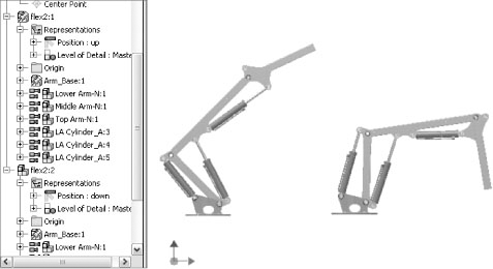
Positional representations also allow the reuse of identical subassemblies within a top-level assembly file. When using positional representations in conjunction with flexible assemblies, you can illustrate a subassembly in different positions. Figure 8.43 shows an assembly containing two instances of the flex2.iam subassembly. The original instance, flex2:1, has the positional representation set to Up. The second instance has its positional representation set to Down.
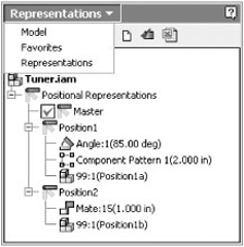
To help manage positional representations, you can set up the browser to display only the overrides present in each positional representation, as shown in Figure 8.44. The buttons along the top of the Representations browser allow you to create a new positional representation, validate the overrides ensuring that no errors are created in the representations, and manage the overrides via Microsoft Excel.
Because the positional representation properties of an assembly are stored separately, multiple views can be created in the drawing environment representing different positions of the same assembly. Figure 8.45 shows an example of an overlay view showing both available positions of this arm.
Proper use of level of detail (LOD) improves speed and reduces the memory required to load and navigate large assemblies. When working with a large assembly, you suppress components that are not required for a certain aspect of working with the design and then save that suppression state as a level of detail representation. For instance, if you are designing a large material-handling unit, you might open the unit in the LOD representation with everything suppressed except the frame while you work on the frame skins, thereby significantly reducing the number of parts loaded into memory.
Another common example of LOD representations might be to suppress external components while working on internal components simply for convenience. In addition to this standard method of suppressing components to create LOD, you can employ substitute LOD representations to trade out a large multipart assembly with a single part derived from that assembly.
Just as view and positional representations have master representations, so too does the LOD. However, there are three additional default LOD representations: All Components Suppressed, All Parts Suppressed, and All Content Center Suppressed. These system-defined LODs cannot be removed or modified.
- All Components Suppressed
Suppresses everything within the assembly, allowing you to quickly open the assembly and then unsuppress components as required.
- All Parts Suppressed
Suppresses all parts at all levels of the assembly; however, subassemblies are loaded, allowing you to examine the assembly structure without loading all the part files.
- All Content Center Suppressed
Suppresses any component in the assembly that is stored in the Content Center Files directory as designated by the IPJ (project) file.
Although Chapter 9 covers the specific steps to create LODs, here are the general procedures.
To create a user-defined LOD, follow these steps:
Expand the Representations heading in the browser, right-click the Level Of Detail heading, and then choose New Level Of Detail.
Continue by right-clicking the component or components you want to suppress, and choose Suppress from the menu.
Once this is done, you must save the assembly while still in the LOD.
After saving the assembly, you can create more LOD representations or flip from one to another to compare the results.
To create a substitute LOD, follow these steps:
Expand the Representations heading in the browser, right-click the Level Of Detail heading, and then choose New Substitute.
There are two methods for creating substitutes. The first method simply prompts you to select any existing part file to swap out for the assembly file in the LOD, and the second creates a derived part from the source assembly.
When using the Derive Assembly method, you are asked to specify a part template to use and then are brought right into the derive assembly process.
The derived part is automatically marked as a substitute during the derive process and placed into the LOD.
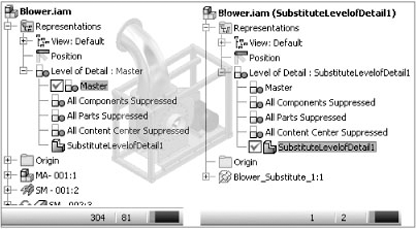
On the left, Figure 8.46 shows an assembly in its master LOD with 304 component occurrences in the assembly and 81 unique files open in the Inventor session. On the right, the same assembly is set to a substitute LOD and reduced to a single component in the assembly and only two unique files open in the Inventor session. As you can imagine, you can achieve a significant savings in memory by placing an assembly with a substitute LOD active into a top-level assembly.
It is important to understand that substitute LODs are intended to be used by either excluding components during the derive process or in combination with user-defined LODs to exclude components. Simply making a substitute LOD of an assembly with all components included may not give you the performance gain you anticipated unless you have made the substitute from another LOD that has parts suppressed or you have excluded parts while creating the substitute LOD.
LOD states are created automatically when you suppress components while in the master LOD. To save suppressions to a new LOD representation, click Save, and you will be prompted to click Yes or No to save the LOD. If you choose Yes, you can specify a name for the LOD. If you choose No, the suppression states of the component are discarded, and the assembly is saved in master LOD.
Temporary LOD representations are created in subassemblies when a subassembly component is suppressed from a top-level assembly. A tilde and index number are listed after the subassembly name to denote a temporary LOD state. Note that the subassembly is not modified. You can open the subassembly on its own and save the suppression states as a named LOD if desired.
It is important to understand the difference between LOD representations and iAssembly configurations with respect to how they affect the bill of materials. Although you can suppress features at will and substitute part files for assemblies with the use of LOD representations, Inventor still understands that all the parts in the master LOD will be included in the bill of materials. When you suppress a component in an LOD representation used in a drawing view, the view updates and any balloons attached to that component are deleted. However, the parts list will still list the component because it always refers to the master bill of materials.
If your intent is to create an assembly configuration where some parts are to be listed in the bill of materials and others excluded, iAssemblies is the correct tool.
An iAssembly is a table-driven assembly file that allows the use of component part configurations to build variations of a design. Some of the strengths of assembly configurations of this type are the abilities to swap out one component for another, to include or exclude components all together, and to adjust assembly constraint offset values to create various configurations of the original assembly.
It is important to understand that when you create an iAssembly, you create what is called an iAssembly factory. The configurations that will be output from this factory are called the iAssembly members. It may help to think of the factory as the parent file and the members as children.
To create an iAssembly, most often you start with an assembly composed of iParts. First, the iParts are created for all parts that will vary in size or configuration of features. Next, create the assembly using iPart members where required. Once the basic assembly is created, you add the configuration table, turning the assembly into an iAssembly.
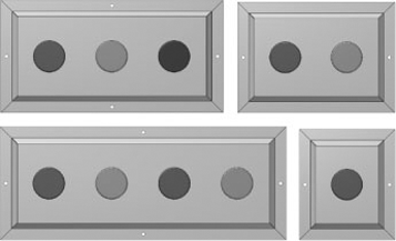
The assembly used in the next exercise represents a simplified push button panel. Your goal is to create an assembly configuration with variations in the number and type of buttons used, as shown in Figure 8.47.
On the Get Started tab, click Open.
Browse to Chapter 8 in the Mastering Inventor 2010 directory, and open
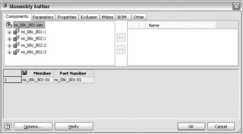
mi_08c_001.iam.Switch to the Manage tab, and click Create iAssembly on the Author panel. This will open the iAssembly Author dialog box, as shown in Figure 8.48.
The first thing you should do is consider the naming conventions for the iAssembly members. Click the Options button at the bottom of the dialog box to bring up the naming options. Here you would typically configure the name for the member part number and member names so that, as you add rows to the iAssembly table, the naming drops out automatically. In this case, we'll simply click OK to choose the defaults.
Either column can be set to be the filename column from which member part numbers are generated. This can be done by right-clicking the Member or Part Number column headers and choosing File Name Column from the menu. The filename column is indicted by the save or disk symbol.
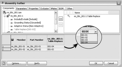
Next, let's examine the Components tab and expand the tree next to part mi_08c_001:1. In the tree of each part are four different nodes that you can use to add a column to the table. Select Table Replace from the tree, and use the >> button to add it as a column in the table. Now that you have added a column to the table, you will add a row. Right-click anywhere on row 1 in the lower pane of the dialog box, and choose Insert Row. Your table should now resemble Figure 8.49.
The table replace column allows you to replace an iPart member for another iPart member within the assembly. In this case, the part named 801 is the sheet-metal cover plate. This plate is an iPart that has four different sizes within the iPart table.
Click the cell in row 1 in the mi_08c_001:1 Table Replace column to activate a drop-down menu. From the menu, select 001-04, as shown in the inset of Figure 8.49. Click OK to exit the dialog box.
You will notice that the model has changed from a three-hole plate to a four-hole plate. This is a result of having set the Table Replace cell to use the iPart member 001-04, which is predetermined in the iPart to be a four-hole plate.
Examine the Model browser, and you will notice that a table has been added to the browser. Expand the table, and you will find a listing of the iAssembly members, mi_08c_001-01 and mi_08c_001-02.
mi_08c_001-01 will have a check mark next to it informing you that this is the active member of the iAssembly. To set mi_08c_001-02 as active, right-click it and choose Activate, or simply double-click it. Then double-click mi_08c_001-01 to set it back as the active member of the table.
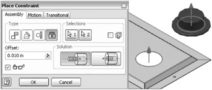
Now that you have used a different size plate, you will need to add another button to the assembly. To do this, simply select one of the existing instances, and use Copy and Paste to add a new instance.
Next, place an Insert constraint between the new instance of the button and the empty hole on the plate, as shown in Figure 8.50.
Once the new button is constrained, set mi_08c_001-02 active again in the table tree, and notice that you are presented with an error message warning you that the new constraint is looking at geometry that is no longer present. Click Accept in the error dialog box.
Notice the new button remains even though the hole it was constrained to is gone. To address this, you need to edit the table further and configure the iAssembly to suppress the extra button when not needed.
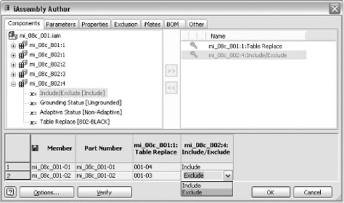
Right-click the Table icon in the Model browser, and choose Edit Table.
Locate part mi_08c_802:4 in the tree as shown, and use the >> button to place Include/Exclude in the table as a column.
Next, set the value for this column to be Exclude for row 2, as shown in Figure 8.51. Click OK to return to the model, and activate both members to see that no constraint errors occur.
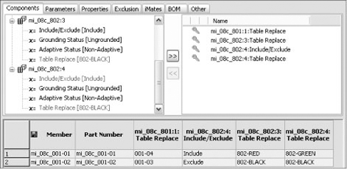
Next, you will change out the black buttons in member mi_08c_801-01 to use a second green and a second red button. Edit the table, and choose the last two instances of part mi_08c_802 (the button) from the tree in the top-left pane. Locate the Table Replace parameter for each, and use the >> button to include them in the table. Set the Table Replace values in row 1 to Red and Green, as shown in Figure 8.52. You do not need to change the values in row 2 because one of the buttons is already set to Black as required and the other, as you recall, you excluded so that it does not show in the row 2 configuration. Click OK to exit the table authoring dialog box, and note the changes to configuration mi_08c_001-01 in the iAssembly Author dialog box.
Lastly, let's set one of the buttons to be in a different position. Edit the table to return to the iAssembly Author dialog box again, and activate the Parameters tab. Expand the Constraints folder, select Insert:1, and use the >> button to add it as a column in the table. Set the value of this column to 0.25 inch for row 1 of the configurations. Click OK to exit the dialog box, and notice the first button is enabled because you have modified the constraint offset value.
- Organize designs using structured subassemblies
Subassemblies add organization, facilitate the bill of materials, and reduce assembly constraints; all this results in better performance and easier edits. One of the habits of all Inventor experts is their effective use and understanding of subassemblies.
- Master It
You need to hand off an accurate BOM for finished designs to the purchasing department at the end of each design project.
- Use positional reps and flexible assemblies together
Often you may need to show a design in various stages of motion to test interference and/or proof of concept. Copying assemblies so that you can change the assembly constraints to show different assembly positions can become a file management nightmare. Instead, use flexible subassemblies and positional representations.
- Master It
You need to show your assembly in variations dependent upon the position of the moving parts and the task the machine is accomplishing at given stages of its operation.
- Copy designs
Because of the live linked data that exists in Inventor assemblies, using Windows Explorer to copy designs and rename parts is difficult and often delivers poor results. Using the tool provided in Inventor will allow you to copy designs and maintain the links between files.
- Master It
You need to duplicate an existing design in order to create a similar design.
- Substitute a single part for entire subassemblies
Working with large assemblies, particularly where large, complex assemblies are used over and over as subassemblies within a top-level design, can tax almost any workstation if not approached in the correct manner.
- Master It
You would like to swap out a complex assembly for a simplified version for use in layout designs or to use in large assemblies in an attempt to improve performance.