
In this chapter, we will introduce the concept of design the "Inventor way," recognizing that many users of Autodesk Inventor are transitioning from the 2D world of AutoCAD or from one of the many other 3D modeling packages available today.
The change is not painful, provided you fully understand the concepts and workflows in creating efficient, accurate models and drawings.
In this chapter, you'll learn to:
Use the Ribbon bar in Autodesk Inventor
Utilize the Inventor Model browser
Understand the various file types used in Inventor
Understand basic principles of parametric design
Understand the differences between solid and surface modeling
Develop best practices for using Autodesk Inventor
To the experienced AutoCAD user, Inventor may seem extremely foreign and difficult to use. In actuality, Inventor is much simpler to learn and use than AutoCAD. The key to grasping the concepts of part creation in Inventor is to set aside the methods of AutoCAD design and embrace a new and more powerful way to approach computer-aided design.
AutoCAD was developed as a general-purpose drafting tool. Although there have been many enhancements over the years, it is still basically an electronic drafting board.
Inventor was developed as a mechanical design tool. In Inventor, you focus on creating a model of your design. Just like a machine is made of parts and assemblies, you create parts and assemblies in Inventor.
Many commands in AutoCAD are very specific. For example, there are different dimension commands for lines, angles, and circles. Inventor has only one general dimension tool that creates the appropriate dimension based on what you select.
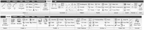
At the top of Figure 1.1 is the 2D Sketch tab that you use to create and dimension the sketch profiles. Upon the completion of a sketch, simply right-click and then choose Finish Sketch in order to allow the creation of a part feature. Once you do this, the Ribbon automatically switches to the Model tab, as shown at the bottom of Figure 1.1.
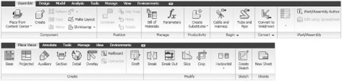
When working with assemblies, the tool tab changes to the Assemble tab (as shown at the top of Figure 1.2). When you create a 2D drawing of parts or assemblies, you see the Place Views tab, as shown at the bottom of Figure 1.2.
As you can see, the tabs on the Ribbon change with every environment. With a task-based user interface, there is no need to display every possible tool.
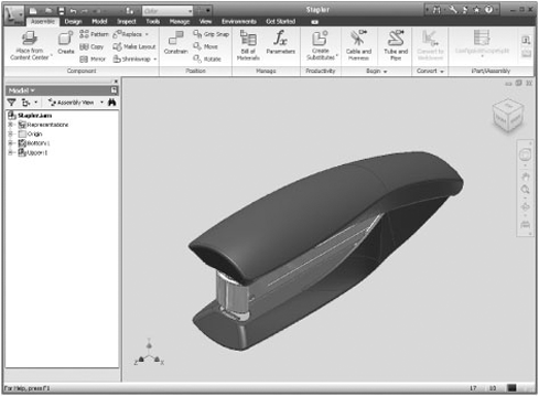
The Inventor graphical interface might be different from what you're used to in AutoCAD. In Figure 1.3, you can explore the entire Inventor window, which shows an assembly file open for editing.
Starting at the upper left of the Inventor window, the Inventor button has a drop-down panel that is similar to the File menu in previous versions. The title bar now includes two toolbars:
You can customize the Quick Access toolbar for each file type by selecting and deselecting icons from a list, but you can't rearrange them. The custom part modeling toolbar in Figure 1.4 shows all the icons in the same order as they appear on the list.
Table 1.1 defines all the Quick Access toolbar icons available for the different file types.
The Help toolbar, shown in Figure 1.5, gives direct access to help files and Autodesk websites. Table 1.2 defines each Help toolbar icon.
Inventor has two sets of tools for manipulating the graphics window:
The ViewCube is used to change the view orientation.
The navigation bar has tools such as Zoom and Pan.
The ViewCube, shown in Figure 1.6, is a 3D tool that allows you to rotate the view. Here are some viewing options:
If you click a face, edge, or corner of the cube, the view rotates so the selection is perpendicular to the screen.
If you click and drag an edge, the view rotates around the parallel axis.
If you click and drag a corner, you can rotate the model freely.
If you click a face to have an orthogonal view, additional controls will display when your mouse pointer is near the cube.
The four arrowheads pointed at the cube rotate the view to the next face.
The arc arrows rotate the view by 90 degrees in the current plane.
If you click the Home icon, the view rotates to the default isometric view. If you click the drop-down arrow, you have several options to change the default isometric view behavior. For instance, you can modify the home view to any view you like, and you can reset the front view in relation to your model so that the named views of the cube match what you consider to be the front, top, right, and so on.
Table 1.1. Quick Access Toolbar Icons
Table 1.2. Help Toolbar Icons

The navigation bar is located on the right side of the graphics window. At the top of the bar is the steering wheel. Below the steering wheel are the other standard navigation tools: Pan, Zoom, Orbit, and Look At. Figure 1.7 shows the navigation bar.
You can use the navigation bar's steering wheel to zoom, pan, walk, and look around the graphics area. Also available is the ability to rewind through previous steering wheel actions. The steering wheel has more functionality than can be explored in this book. You should review the help topics for more information (click the steering wheel and then click F1).
The Ribbon bar is similar to AutoCAD 2009 and Microsoft Office 2007 in that it is composed of tabs and panels. Each tab contains commands for a particular task, such as creating drawing views, and each panel contains related commands. The Ribbon will change to the proper tab based on the current environment (for example, sketching or assembly modeling), but you can select a different tab as needed.
You can customize the Ribbon bar by doing the following:
Turning off command text, reducing icon size, or using a compact icon layout
Turning off panels that you don't use
Adding frequently used commands to a tab
Minimizing the Ribbon
Undocking the Ribbon so it becomes a floating tool palette
Docking the Ribbon on the left, right, or top of the Inventor window
Most of the icons on the Get Started tab, shown in Figure 1.8, link to help topics. The Show Me Animations tool is one of the most useful help tools. It links to a comprehensive set of short videos that show you how to accomplish tasks in Inventor. You can use these to your benefit as quick reminders for tasks that you may not complete often and just need a helpful reminder of how a particular tool works.

The View tab, shown in Figure 1.9, has controls for object visibility and appearance, window control, and navigation. There are some variations in the icons, depending on the environment, but most of the icons are used in all of the modeling environments.
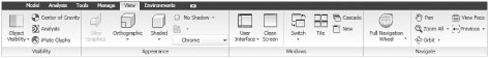
The Visibility panel on the View tab has tools for controlling which objects are visible. When you click Object Visibility, a large list is displayed so that you can control the appearance of your graphics window.
The Appearance panel has tools for controlling the way models are displayed. You can switch between orthographic (parallel model lines appear parallel) and perspective (parallel model lines converge on a vanishing point) views, display the model as shaded or wireframe, and use drop or x-ray shadows.
Most of the tools in the Windows panel are standard controls, such as switching tiling windows. If you click User Interface, a list of items such as the ViewCube and the status bar are displayed. The Clean Screen icon hides most of the UI elements. Only the title bar and a minimized Ribbon bar are displayed. Click the small drop-down arrow to return to the display of the tool panels.
The tools in the Navigate panel are the same as those found on the navigation bar, as discussed earlier in the chapter.
The browser pane is a listing of everything that makes up an Inventor file. The part browser shows all of the features, the assembly browser shows all of the components, and the drawing browser shows the sheets with the views. Because Inventor files are similar to actual parts and assemblies, the browser plays an important role in navigating the files. In this section, we will explore the behavior of the browser pane when working in Inventor:
With Inventor open, ensure you have no files open in the current session.
Next click the Get Started tab, and then click Projects. This opens the Projects dialog box from which you can select the Samples project that Autodesk has provided for you as part of the installation of Inventor.
To set this as the active project, click the Apply button toward the bottom of the dialog box. Once the project is active, you will see a check mark next to the project name.
Now that the Samples project is set to be the current one, you can click Done and then close the Projects dialog box. (You'll find a more detailed explanation of working with and setting up projects in Chapter 2.)
To open the assembly, go to the Get Started tab, and click Open.
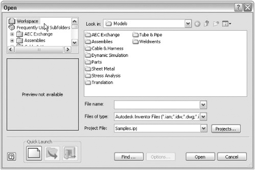
To ensure that you are looking at all the files in the Samples project (and only the files in this project), click Workspace in the Open dialog box, as shown in Figure 1.10.
Browse for the file called
Stapler.iam, located atModelsAssembliesStapler.
When opening your current assembly file (Stapler.iam), the Assemble tab of the Ribbon bar is active. You'll notice that in the Model browser (to the left of the screen) all items are shown in a white background, with no portion of the Model browser grayed out. You are currently in the top level of the assembly, meaning that the uppermost level of the assembly is currently active.
Double-click the subassembly called Bottom (to do this, you simply click twice quickly on the grounded assembly icon next to the word Bottom). Note that it is best practice to get into the habit of double-clicking the icon next to the component name, rather than the name itself, because the latter may initialize an edit of the name depending upon the speed of your clicks. Double-clicking the icon will activate the subassembly for editing in place, within the Stapler assembly. Once this subassembly is activated, all other portions within the Model browser will be grayed out.
With the Bottom subassembly activated, you will notice the Assembly panel is still visible. Next double-click the part icon for Bottom-Back. This activates the single part for editing. You will notice that the Ribbon bar has changed and the Model tab is active. The Ribbon bar change reflects that you are now editing a part file, and are therefore working at the part editing level of the model hierarchy, with part feature tools ready for selection.
With the part active for editing, you will notice that the Model browser now shows all the features present in the active file. Examining these features within the active part, you can see the standard origin features, some user work planes, some additional features such as extrusions, and a fillet feature. You will also notice a red X at the bottom of the part signifying an end-of-part (EOP) marker.
To return to the top-level assembly, you can simply double-click the filename (Stapler.iam) at the top of the Model browser, or you can click the Return icon at the top of your screen. Each click of the Return icon will move you up one level in the assembly. Regardless of which method you use, you will notice that the Ribbon bar returns to the assembly tools (from the part feature tools) once you are back to the top-level assembly.
As demonstrated in this quick tour of a typical assembly structure, the Inventor Ribbon tabs are unique and intuitive to the environment you are in at the time. In the next example, you will explore the changes encountered in the Styles Editor located on the Format tab.
In addition to the Ribbon bar updating based on the current environment, as described in the previous section, some Inventor dialog boxes are also task-based. Instead of containing every control needed for every environment, the dialog box displays only the controls necessary for the current task. Follow these steps to see an example of this:
While in an assembly file, with either the top-level assembly or a subassembly active, select the Manage tab and then select Styles Editor, as shown in Figure 1.11.
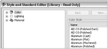
When the Style And Standard Editor dialog box opens, the styles relating to the assembly file will be shown, as in Figure 1.12. You will notice that while in assembly or part mode, three style areas are available: Color, Lighting, and Material.
From the Get Started tab, click the New button.
With the new drawing file active, select the Manage tab, and then click the Styles Editor button. You will see that the style area option reflects styles pertaining to drawings, as shown in Figure 1.13.

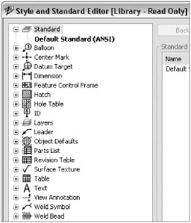
An IDW or DWG drawing style contains various dimension styles, layers and layers names, line type settings, object defaults, text styles, and other settings related specifically to 2D drawing styles. These drawing styles relate and translate to AutoCAD drawing styles and layer names. In like fashion, the presentation file type (.ipn) style types include only Color and Lighting configurations.
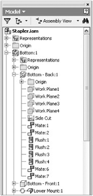
Inventor has what is called a Model browser that reflects the content in order of features, subassemblies, and parts contained within the current file. In Figure 1.14, the Stapler.iam file provides a good example of the Model browser contents of an assembly file. The figure shows a representative assembly model with the browser expanded.
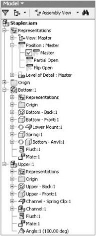
In this figure, starting from the top, you can see a folder containing representations, including view representations, position representations, and level of detail (LOD) representations. These representations allow the user to create various view states of the assembly. For example, Figure 1.7 shows that the Position folder contains a view called Flip Open, which represents the stapler in a fully hinged open position. In Chapter 8, you'll find more information about representations.
To expand any portion of the Model browser, click the plus sign to the left of the item. For example, clicking the plus sign at the left of the Representations folder expands the item to show View, Position, and Level of Detail.
Moving further down the browser tree, you'll encounter another folder called Origin. Each part and assembly file contains an Origin folder. In this example, the first Origin folder you encounter is the assembly origin. The assembly origin folder contains basic YZ, XZ, and XY work planes, work axes, and the origin center point. These work features comprise the origin of the assembly file, and it is this origin that provides the starting point for placing files within the assembly. These work features in the origin plane are defaults and cannot be deleted; however, you can change the visibility of these work features as required by right-clicking them.
Next in line in this example is the first file that was placed within the assembly file. In this case, it is another assembly called Bottom. An assembly placed into another assembly is typically called a subassembly. You will notice that there is a pushpin icon next to the filename. The pushpin represents a grounded component, which means that the component is currently set to its current X, Y and Z coordinates and cannot accidentally be moved. The first file inserted into an assembly file is always automatically grounded. The grounded status of a component can be turned on and off, and in fact all or none of the parts in an assembly can be grounded. However, it is best practice to ensure that at least one component is grounded in order to prevent problems generating orthographic views in the 2D drawings.
You will notice that the same Representations and Origin folders exist in this grounded assembly and in all other parts and assemblies that exist in this file. The relationships between origin planes in each of the files provide a permanent reference for downstream modifications, including 3D constraints and editing of individual parts.
In the subassembly called Bottom, there are additional files: Bottom-Back:1, Bottom-Front:1, Lower Mount:1, Spring:1, and Bottom-Anvil:1. Each of these files represents a separate part within the subassembly. The 1 that follows each part represents the first instance of that part name within the assembly. If a second identical part name is inserted within the same assembly, the number would be incremented according to the number of times that part is instanced within the assembly.
In the browser, note that two of the parts, Lower Mount and Bottom-Anvil, have a red-and-green icon preceding the part name. This icon tells the user that these two parts are set to be adaptive, meaning that these two parts will automatically adjust to changes in the part they reference. Right-clicking the Adaptive icon will display a context menu, allowing the user to turn adaptivity on or off.
Next to each part name within the subassembly is a small plus sign, signifying that the part or subassembly can be expanded to show more of the contents of that specific part (see Figure 1.15). When the part or subassembly has been expanded, the plus sign switches to a minus sign, which allows the user to compress the part or assembly back to a smaller state and save room for reviewing other items within the Model browser.
At the bottom of this section within the browser, you will see the words Flush and Mate. The Flush and Mate references are two of several 3D constraints used to "assemble and constrain" various parts. Right-clicking a constraint in the browser allows the user to locate the other part to which this part is constrained within the assembly.
In AutoCAD, you might be used to having the DWG file format as your main file format. Inventor, on the other hand, follows the structure common to most other 3D modelers in the engineering field today. Instead of placing all information in one file, the data load is distributed into many different files. Placing the data in multiple files permits higher performance, promotes file integrity, and vastly improves performance on large designs. As you've already explored, having different file types allows you to have environment-specific tools for working with each file type.
The payoff of multiple file types is exemplified in the comparison between the way that AutoCAD handles model space/paper space and the way that Inventor handles the same tasks. To put it simply, in Inventor the part and assembly files represent model space, and the drawing file is in effect paper space. Using multiple file types to handle the separate tasks required for modeling vs. detailing simplifies the interaction between both tasks, and as a result, the headaches of managing model space and paper space in AutoCAD are eliminated in Inventor.
Here are the primary file formats commonly used in Inventor:
.ipj: Inventor project file.ipt: Inventor single part file.iam: Inventor assembly file.ipn: Inventor presentation file.idw: Inventor 2D detail drawing file.dwg(Inventor): Inventor 2D detail drawing file.dwg(AutoCAD): AutoCAD nonassociative drawing file.xls: Excel files that drive iParts, threads, and other data
Although this list may seem intimidating, once you get used to using Inventor, having many different file types will be less of a concern. The benefit of using multiple file types to have fully associative, automatically updating designs is a cornerstone of most 3D parametric modelers. Performance and stability in the use of Inventor require good data management principles, including storing the saved files in an efficient and organized manner. We'll introduce this subject later in this chapter and expand upon it in Chapter 2.
You can use DWG files in a number of ways in Inventor. Although Inventor does not support the creation of AutoCAD entities, you can utilize AutoCAD geometry in Inventor sketches, Inventor drawings, title blocks, and symbol creation.
When creating a new part file in Inventor, you can copy geometry directly from an AutoCAD DWG and paste it into an Inventor sketch. AutoCAD dimensions will even be converted into fully parametric Inventor dimensions. However, only minimal sketch constraints will be created when doing this. Using the Auto Dimension tool within the Inventor sketch environment, you can apply sketch constraints to the copied AutoCAD data quickly. It is important to remember that many AutoCAD drawings contain fundamental issues such as exploded or "fudged" dimensions and lines with endpoints that do not meet. Copying such drawings into an Inventor sketch will of course bring all of those issues along and will typically provide poor results.
Another way to use AutoCAD data in Inventor is in an Inventor DWG file. Often you'll have symbols in AutoCAD in the form of blocks that you want to use on a drawing in Inventor, such as a directional flow arrow or a standard note block. Although you could re-create these symbols in Inventor, you can also simply copy the block from AutoCAD and paste it into the Inventor DWG. This functionality exists only within an Inventor DWG and is not supported in an Inventor IDW. In fact, it is one of the few differences between an Inventor DWG and an Inventor IDW.
Mechanical Desktop DWG files can be opened or linked into Inventor assemblies. When the Mechanical Desktop file is opened in Inventor, options allow the translation of Mechanical Desktop models into parametric Inventor parts and assemblies, as well as fully associative layouts into Inventor drawing files. When the Mechanical Desktop file is linked into an Inventor assembly, it behaves similarly to an AutoCAD XRef, and all edits will be maintained using Mechanical Desktop.
Users of Inventor may often find that they are called upon to create native DWG files from Inventor IDW files for use by customers or other people within the company. A user may create a DWG file by simply performing a Save Copy As and saving it as an AutoCAD DWG file. The newly created DWG file will not be associative to the Inventor part or assembly or IDW file and will not reflect any changes made to the part, assembly, or Inventor drawing file. It is common to use Save Copy As on an Inventor drawing and save it to an AutoCAD DWG just before making revision changes, thereby preserving a copy of the drawing in a static state at that revision level. Once the static copy is saved, revision edits can begin, and the original Inventor drawing will update automatically.
Beginning with Inventor 2008, users have the option of creating a native Inventor DWG file in place of the IDW file. This DWG file will behave exactly like an Inventor drawing file, except that the file extension will be .dwg instead of .idw. Just like an IDW file, an Inventor DWG file will update whenever parts or assemblies linked to the file are changed and updated. Note too that if you have IDW files that were created in a version of Inventor previous to Inventor 2008, you can save those files as fully associative DWG files so that your drawing library contains one consistent drawing file type. This process can even be batched and scheduled to run overnight using the Task Scheduler, which you can open by selecting Start
You can open an Inventor DWG file in AutoCAD and edit it with some limitation. The primary limitation is that the Inventor objects are protected from modification. AutoCAD dimensions and other entities can be added and will remain intact when the file is opened again in Inventor, but as a rule, objects must be edited in the application from which they were created.
Another aspect of working with an Inventor DWG in AutoCAD is that whereas the Inventor DWG does not contain a model space by default, once it is opened in AutoCAD, you can access model space. From model space in an Inventor DWG, you can use the Insert command to place the Inventor drawing views of the model as AutoCAD blocks. These blocks will update automatically so long as they are not exploded and remain in the current DWG. However, you can explode the blocks and copy them into other DWGs without worrying about having a negative impact on the Inventor DWG. If objects such as these blocks are added to the DWG's model space in AutoCAD, you will then be able to access model space for that file in Inventor. However, you will be able only to view, measure, and plot the model space objects.
If you are moving from AutoCAD 2D to Inventor 3D modeling, you can have a great experience in the process if you put design concepts used in AutoCAD on the shelf while learning this exciting design tool.
If your experience is like that of many others who made the transition from the drawing board to drawing lines in AutoCAD, it was difficult to say the least. At first you may have been frustrated with spending more time creating electronic drawings than it would have taken to produce the drawing with the board. However, a key reason for the acceptance of AutoCAD was the ability to make edits far more quickly than you could with eraser and paper. Once you master Inventor, you will find the same benefit of faster edits, as well as the many benefits that parameter-based design has to offer.
Making the move to Inventor successfully requires some evaluation of current methods of design in AutoCAD. The following are some of the evaluation steps in planning your successful move:
Assess your current directory structure of AutoCAD drawings. How do you store, name, and reuse current AutoCAD files? Will the structure be compatible for storing Inventor documents, or is it time to take a deep look at your data management structure?
Determine how you will manage Inventor files. Inventor utilizes projects to manage assemblies, drawings, and associated part files. What worked in AutoCAD will probably not be the ideal scenario in Inventor.
Document your current design workflow when using AutoCAD. Is it time to reevaluate the design process in light of the efficiencies that may be gained when using Inventor? How are revisions, engineering change orders, and production currently being managed, and how can Inventor improve on the design-to-manufacturing processes?
Determine whether your current computer hardware and network are up to the task of implementing and using Inventor. What gets by for using AutoCAD seldom will work for the demands of 3D modeling in Inventor.
Set aside time for training and implementing Inventor. If you have multiple users, it might be best to consider phasing Inventor in over a period of time, allowing new users to acclimate themselves to a new way of design.
If you take the time to plan your leap into Inventor, your chances of success are greatly improved. The rewards of a successful transition are great!
In future chapters, we will expand on the evaluation tools needed to plan a great transition, but first you need to learn what is expected from Inventor. To do that, let's enter the world of 3D design.
Common to machine design, actual prototypes are built to test or validate the design, and they help discover weaknesses or areas that require redesigning. It is a costly and time-consuming process but one that is needed when working from 2D designs.
Even the best engineer or designer cannot anticipate everything needed to create an accurate design the first time around. Mistakes are made, scrap is generated, and redesign and retooling are needed. The entire prototyping process is expensive and time-consuming.
But creating prototypes is part of the old way of doing things. It worked when you made 1,000 of something and had plenty of time and resources to lend to the project. It worked when material costs were relatively low. In today's competitive market, you most likely have no such luxuries of time and materials. More and more often, manufacturing and design are pressed by worldwide competition for products, jobs, and manufacturing bases.
The emphasis is on designing and building something quickly and economically, without sacrificing quality or performance. Many companies today specialize in custom machines and automation where the "prototype" is the end product. Clearly, anything that can be done to reduce or eliminate prototyping will greatly influence your financial health and competitive strengths.
Over the years, as designs tools have evolved, so too have the ways we design. However, it is possible to use new design tools in the same manner we used the old tools if we are not careful. As companies moved from the drafting board to AutoCAD, many users continued to use AutoCAD in much the same way they used the board. Not reusing data in the form of blocks and block libraries and not employing block attributes to pack those blocks with intelligence are common examples of this.
In much the same way, it is possible to use Inventor like it is AutoCAD. Creating 3D models simply for the sake of generating a 2D shop print is a common example of this. To ensure that you are getting the most out of Inventor, you want to ensure that your designs are more than 3D models and are in fact virtual prototypes. You want to ensure that your 3D models are more than a collection of related features and instead relate parameters from one feature to update based on the edits of another to reflect the intent of the overall design. You want to build a digital prototype in every sense of the word, anticipating change and revision and making it as robust and intelligent as you can.
So, what is a 3D virtual prototype? Put simply, it's a digital prototype that has not yet been built. And although that simple answer seems obvious, it is the "not yet built" part of that description that is key. A virtual prototype is a completely digital 3D parametric model that functions the same way a real mechanism should. It is far more than a just a 3D model.
The virtual prototype consists of a main assembly, which contains many subassemblies that have individual parts. All these components are constrained in such a way that the fit and functionality of all parts and mechanisms can be visualized, tested, and proven before any parts are manufactured. Scrap and rework are virtually eliminated if the design is fully completed and proven in the digital form.
Making the virtual prototype allows the designer to explore the function of a mechanism before lengthy design and engineering time is expended on a design that just won't work. Developing the virtual prototype eliminates the part procurement and creation process, slashing the design time even further.
The virtual prototype can be proven with the use of stress analysis and dynamic motion simulation to find and correct weaknesses in the design, rather than just ensuring that everything is overbuilt and calling it a good design. Interference between components is also easily discovered while still in the design process.
The use of functional design in the prototyping process allows engineers to properly determine loads, power, stresses, inertia, and other properties before a machine is built. Weights, center of gravity, and other physical characteristics are at your fingertips during any stage of the design.
In 2D design software such as AutoCAD or other legacy packages, including most surface modelers or 3D modelers capable of creating static models, the ability to modify the design is typically limited. Modern 3D feature-based modelers provide the ability to easily change virtually any part of the design within the model.
This ability to change or modify a design is based on constraints that control either the shape or the size of a feature. The combination of geometric constraints and dimensional constraints allows virtually any variation within the model.
Most of today's 3D modeling systems utilize the same 2D constraint manager. As a result, the 2D constraints in use today are virtually identical from one software package to another. In like fashion, the dimensional constraint systems are similar from one software package to another, and these similarities allow you to more easily learn a second 3D modeling system the next time around.
Let's start on familiar territory with software that most of us have used in the past: AutoCAD. When you created a design in AutoCAD, that design was not much different from creating the same design on a drawing board. In AutoCAD you can draw precise lines, arcs, circles, and other objects, placed precisely and with accurate dimensions reflecting your design, in a way that you cannot do by hand. When a design requires modification, you erase, move, copy, stretch, and otherwise manipulate the existing geometry more quickly than you can by hand as well. But other than those gains in speed and accuracy, the workflow is much the same as working on a drafting board. In short, AutoCAD automates drafting tasks but does less to speed up the design process.
Standard dimensions in AutoCAD are what we call driven or reference dimensions. A driven dimension is controlled by the geometry, and it reflects the actual value of the geometry that is referenced by the dimension. If you stretch a line, for example, the dimension that is attached to the line will update to the new value. If you think about it, the only reason for a dimension on a 2D drawing is to convey the value of a feature or part to a person who is going to build it. If you import that 2D file into a CAM package, no dimensions are needed because the line work contains all the information about the part.
The workflow in a 3D model is substantially different from in 2D modeling. In a 3D model, you create sketches in 2D and then add geometric constraints such as horizontal, vertical, parallel, and so on. Adding the geometric constraints allows line work to adjust in a predictable and desired manner and helps control the overall shape of the sketch. Once geometric constraints are in place, you add parametric (driving) dimensions to the sketch geometry. By changing the value of the dimension, you change the size of the sketch object. As you can see, the Inventor dimension is far more powerful than the standard AutoCAD dimension because it not only conveys the value of a feature or part but also serves as a design parameter, allowing you to change the dimension to change the design.
Parametric feature-based modeling relies on the creation of numerous features within the model. By creating a number of features within the model, you are able to independently change or modify a feature without rebuilding the entire model. An example of editing a feature would be changing the radius of an edge fillet.
Parametric model features are typically either dependent or independent of one another. A dependent feature is dependent upon the existence or position of a previously created feature. If that previously created feature is deleted, then the dependent feature either will also be deleted or will become an independent feature. An independent parametric feature is normally based upon an origin feature such as a work plane, work axis, or work point or is referenced off the original base feature.
Functional design is an Autodesk term for a knowledge content tool that moves the user from creating geometrical descriptions to capturing knowledge. Engineers and designers can use functional design to analyze the function and solve the design problems, rather than spending time on modeling a solution needed to create 3D representations.
Functional design supports design through generators and wizards that add mechanical content and intelligence to the design. By using the components within Inventor functional design, you can create mechanically correct components automatically by entering simple or complex mechanical attributes inside the generator.
Using the functional design components within Inventor provides many advantages:
You shorten the design and modification process through the use of intelligent components.
You produce a higher level of design quality and accuracy.
Functional design provides a more intuitive design environment, compared to creating complicated geometrical designs.
Functional design can eliminate the need for physical prototypes for the purpose of analyzing stress and movement.
The following portions of Autodesk Inventor are part of the functional design system:
Design Accelerator
Frame Generator
Inventor Studio
AutoLimits
Content Center
Bolted Connection Generator
The Design Accelerator is an important component of the functional design system, providing the user with engineering calculation and decision-making support to identify and place standard components or create standards-based geometry from the input provided by the user. Design Accelerator tools automate selecting standard parts and creating intelligent geometry. The initial design quality is improved by validating against design requirements. Standardization is simplified by selecting the same components for the same tasks.
The Design Accelerator provides a set of component generators and calculators that are able to create mechanically correct standard components automatically by entering simple or detailed information.
The Bolted Connection Generator is one example of a tool that can create and insert a complete bolted connection all at once by sizing the bolt diameter and length, by selecting the right parts and holes, and by assembling all the components together.
The Frame Generator will create internal or external frame assemblies for machines. The Frame Generator functions by creating a skeleton part to define the frame within an assembly file. You then use the skeleton to place and size the frame members. You can then use multiple skeletal models within an assembly to create frame members, and you can create frame members between skeletal models. You can also create frame members from the vertices and edges of existing subassemblies. This ability allows you to build framing between other components within an assembly.
Joining frame members together and adjusting the end treatments for connection between members is a simple matter when using the Frame Generator. Joining frame members with weld gaps and coped joints is supported.
Inventor Studio is an environment within Autodesk Inventor with a complete set of tools for creating and editing renderings and animations. With Inventor Studio you will be able to create animated renderings and photorealistic still images of parts and assemblies to help visualize the appearance and motion of designs before they are built.
Inventor Studio allows you to specify geometry and apply settings for background lights and cameras to create a scene for rendering or animation. You can create and save multiple animations within any one assembly file. You can use Inventor constraints and parameters to drive animations within the assembly file. In addition, any changes that are made in the part or assembly file will be transferred and reflected in the rendering and animation files.
The AutoLimits tool monitors selected aspects of the design relative to boundaries that the user specifies. If results fall above or below the boundary limits, a warning indicator is displayed. AutoLimits can also be used to measure distance, length, volume, mass, and so on. Once AutoLimits are created, they constantly monitor to make sure the design still fits its requirements.
The Inventor Content Center libraries provide the designer with standard parts (fasteners, steel shapes, shaft parts, and so on) and part features. You can access the Content Center libraries from the Content Center in the Assembly tool panel, and you can share the libraries between users to provide a high level of standardization.
The Content Center dialog box permits you to look up and insert standard parts and features into an assembly design. You can create custom Content Center folders to allow users to create custom parts for use within the Content Center. Content Center parts allow users to specify ANSI, DIN, ISO, and other international standard parts within the design environment.
Inventor provides the ability to create parametric models in either solid modeling or surface modeling form. In many cases, you can employ both techniques when creating a single part.
3D modeling began because of the desire to create a 3D wireframe representation of a part. This representation provided early users with the ability to visualize and measure the limits or boundaries of parts they were designing. Wireframes provided a minimal amount of information needed to create a part.
It soon became apparent that much more was needed in a 3D model. Software engineers devised objects called surfaces that could be created from the 3D wireframe model. Creating surfaces permitted the accurate definition of the faces or shapes that would be required in order to machine the design.
This new model description technology revolutionized the manufacturing industry. With surfaces, shapes could be programmed into CNC machines, producing accurate geometry to be used for creating precision parts. Surface modelers quickly jumped into the forefront of leading-edge technology. With surfaces, virtually anything could be designed or created.
However, surface modeling had some shortcomings. Creators of surface models had great difficulty calculating volumes, centroids, and mass. The development of surface modeling technology evolved into the ability to create a collection of watertight surfaces. Modeling kernels were further developed to allow the representation of the watertight collection of surfaces as a solid model composed of faces (surfaces).
Solid modeling got off to a good start in the mid-1980s. The first iteration of solid modeling was the ability to create static, base solids. Like surfaces, base solids were difficult to impossible to edit once created. If a mistake was made in the model, the user started over.
The second generation of solid modeling introduced parametric, history-based model creation with the ability to parametrically modify dimensions and constraints within the model to edit or modify the size or shape of the part. If an error was made in creating the part, users could access the history tree and retrace their steps toward the beginning of the part creation process, selecting the point to rebuild the rest of the model. Unfortunately, with history-based modeling, anything that was previously created from that point forward would be deleted and have to be re-created.
The current generation of solid modelers provides dynamic feature-based parametric modeling, where powerful features can be added, modified, suppressed, deleted, or reordered within the model without having to re-create good geometry. With the introduction of feature-based modeling, 3D became a must-have within the engineering community. Now, complex designs can be quickly created and modified to create virtual prototypes of complex machines without having to cut metal to prove the design.
The following are frequent questions among 3D users: Which is better? Should I use surface or solid modeling? Which should I use? The answer is that you should become proficient at using both and never have to limit your abilities. Both surface and solid modeling have a place in today's engineering environment. Learning to use both proficiently should be on the agenda of every aspiring modeler.
Although solid modeling is preferred by more users, primarily because it is a simpler approach to design, the ability to add surfaces to sculpt or modify a solid model or to add faces that would be difficult to impossible to create using solid model features adds a new dimension to creating a quality model. It's a little thing, but it differentiates an expert user from the rest of the pack.
Let's look at definitions of some of the aspects of solid and surface modeling:
- Wireframe
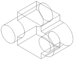
A collection of curves and lines and other geometry is connected into a 3D (XYZ) construction representing the outer boundaries and features of a 3D part. See Figure 1.16 for an example of a wireframe model.
- Surface
A 3D mesh is composed of U and V directional wires or vectors representing a 3D face. Surfaces are generally described by a few different types: polyface meshes (typical in graphics modelers), representing planar faceted faces with joined edges culminating in one face; triangulated meshes (typical in STL files), composed of three-sided planar faces connected into one mesh; and NURBS surfaces (based upon nonuniform rational B-splines), providing smooth, constantly evolving surfaces that can be constrained and made tangent to other adjoining surfaces and providing smooth surface transitions across a single part.
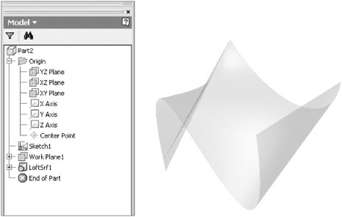
Inventor supports NURBS surface types in created or imported geometry. Inventor surface models, as shown in Figure 1.17, typically display as a translucent object. Surfaces can be combined with solid models in a number of ways to enhance your modeling experience.
- Solid
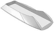
A 3D solid is composed of a collection of surfaces joined together to provide a watertight collection with no gaps or holes. When a collection of surfaces is joined together in such a manner, it is generally considered solidified. Solids can provide the benefit of physical properties such as mass, volume, centroids, and moments of inertia or principal moments and can be tagged with other properties such as material specifications. Figure 1.16 illustrates a solid model part shown in wireframe, whereas Figure 1.17 shows a rather free-form surface. Figure 1.18 shows a solid model in shaded mode that demonstrates the combination of solid and surface model techniques used together to create a complex shape.
Every 3D modeling package follows a workflow designed to produce the best and most efficient design while retaining the stability required to update or modify the design at a later time. In addition, the workflow encourages high performance and stability within the file structure. Inventor is no different from other packages in that an efficient design workflow must be followed to ensure good results.
The following are six important areas to consider when creating an ideal workflow that will both benefit your designs and meet your company's operational requirements:
In the previous pages, we discussed the need for an efficient and practical data management structure that will fit the needs within your company. A good data management structure may be something that your company has already created or something that you may design, keeping in mind your company's and customer's requirements.
Even if your company has been working in other CAD packages for many years, your filing system may be in serious need of reorganization or replacement. Many times, the file structure you find yourself working under today has simply evolved over time as changes in hardware and operating systems have come about. These evolutions range from very inefficient systems with vestiges of some long-gone setup or decision that negatively impacts the way things are done today to very efficient systems where filing is intuitive and well structured. When you implement Inventor, it's a good time to evaluate your system and see what changes are or are not required because of the way that Inventor uses linked files within the application. It is also important to note that parametric modelers such as Inventor create more files than traditional design software.
Redesigning a file management system for efficiency may require the skills of an outside data management consultant who also thoroughly understands the data management structure required for efficient use of Autodesk Inventor and AutoCAD. Or it may mean your IT staff needs to become familiar with how Inventor works with linked files. One qualified individual who can tackle this task might be your local Autodesk reseller, if your reseller has an Autodesk Manufacturing Implementation Certified Expert or Certified Data Management Expert on staff. If such a consultant is not locally available, then you may want to contact Autodesk Technical Services for assistance.
The need to thoroughly evaluate and correct any deficiencies in your current data management structure cannot be overstated. Having a data management system that is set up to ensure the use of unique names for every file should be a primary goal of every Inventor user. This requires some forethought and planning in setting up a good file-naming scheme. Fixing any problems now will deliver a great payback in the use of Autodesk Inventor or AutoCAD.
Selecting the proper project file type after correcting any errors or inefficiencies in your data management structure is crucial to your success with Autodesk Inventor and, in the future, with various AutoCAD vertical applications. The next chapter of this book will introduce you to the different project file types that may or may not be suitable to your specific needs.
If you need to have multiple designers working on a single project simultaneously, it is highly recommended that you investigate Autodesk Vault. Autodesk Vault provides many benefits over other project file types when working in a collaborative system group or even when working alone. Vault is bundled with the Inventor suite and can be installed at the time of your Inventor install or at a later date. Although Vault is a highly effective tool for managing your engineering files, a poorly implemented Vault can cause a lot of headaches. Following the recommendations in this book for setting up a Vault project should keep you in the clear.
On the other hand, you may already have another product data management (PDM) database in use within your company for other applications. You may want to consider integrating Inventor into that PDM system, assuming that your existing system fully accommodates and supports Inventor at least as well as Autodesk Vault. Optionally, you might want to consider an upgrade of the included Autodesk Vault version to one of the other versions with extended functionalities.
If you are working in a smaller company or have just a few users each working on individual jobs with no crossover, the Single User Project file mode might be the best way for you to work.
Paramount to the success of 3D solid modeling is developing an efficient and stable part-modeling workflow that works for your designs. Unlike AutoCAD, where lines are independent of one another, 3D modelers build relationships between features. When you add a boss to the face of a part, there is a relationship. If you make a change to the face that interferes with the relationship, then the boss will fail. In order to build a stable model, you have to think about how the part functions and how the features relate to each other.
Here are a few attributes of good part design:
Sketched part features created from simple sketches that represent and document design intent
Creation of part features that do not have a high degree of dependency upon other previously created part features
Part features that are easily identified and able to be edited without creating errors
Fully constrained and dimensioned sketches and features that will update and behave predictably when other features are edited
Features that are properly named and identified for future editing reference
Part creation workflow that is easily understood by other people, should editing be necessary in the future
Practicing restraint in creating large numbers of duplicate features, when identical features could be combined into a single feature
Adding details later in the design, creating fillet features instead of adding them to sketches, and adding fillets at the end so a change to fillet won't cause a failure in a downstream feature
Developing a good workflow that will be repeated in future design projects, providing consistency and design, and helping others to understand and follow good design practices
One issue that AutoCAD users struggle with is complex sketches. A sketch should have only the geometry necessary to create the feature. If a sketch has more than eight to ten elements, you should try to split it up into smaller sketches.
Developing an efficient assembly structure is essential for success and maximum performance in the 3D modeling environment. Poor assembly design will plague the design process throughout the entire life of the job, often creating large assemblies that cannot be rotated for view, cannot be used to create 2D drawings, or often break down, requiring many hours of repair and constant attention.
You can avoid the nightmares of poor assembly design structure with the proper use and understanding of how assembly files work. A properly designed assembly structure possesses the following qualities:
A top-level assembly will be composed of numerous subassemblies constrained to one another. The use of individual parts within the top-level assembly should be limited.
All components within a top-level assembly must be properly constrained to one another so that they will move or not move as they would in the real world. All adaptive components should have adaptivity turned off when adaptivity is not required at that particular moment.
By limiting the number of components at the top-level assembly, the number of 3D constraints present in the top-level assembly will be limited, improving overall performance. Note that when we say component, we could be referring to a part file or a subassembly file.
Properly created and named design views and/or level of detail (LODs) should be present within the assemblies and subassemblies of the design. Use of either or both will provide flexibility and improve performance in the assembly design as well as the 2D documentation process.
Reuse of library parts (including but not limited to fasteners, purchased parts, or company-standard parts used in multiple designs) will improve consistency and performance when loading assemblies. In addition, placing company-standard parts will eliminate duplication of files and filenames within the data management system.
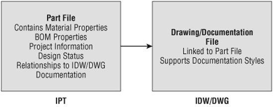
Documenting your designs in 2D drawing files should follow a standard established by your company. However, documenting 3D designs and assemblies using traditional methods and workflows might pose performance and stability issues.
Consider a workflow similar to this: establish a design workflow that encompasses the principle of "one part=one part name/number=one drawing." This establishes a link between just one part file and a single drawing file. This part could be used in many different assemblies and should be documented separately from assembly documentation. Figure 1.19 illustrates this workflow.
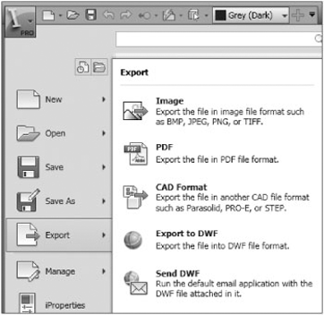
Documentation may take many forms. Inventor offers several options in this area. Your choice of methods may greatly influence productivity downstream. Aside from conventional paper prints generated from an IDW or Inventor DWG file, the Export command allows many options for creating various image formats. Figure 1.20 lists the options available in Autodesk Inventor 2010.
In making the move from two-dimensional to three-dimensional design, you may want to consider modernizing all aspects of your documentation workflow. Now may be the time to move from paper to electronic documentation in all areas where the transmitted information may be utilized.
Instead of plotting paper drawings and having to manage them to make sure that the latest version of each drawing file is properly distributed to all departments, consider using the Autodesk DWF format as a method of recording and documenting IDW or DWG output.
If you are using Autodesk Vault, you could set an option to automatically generate an updated DWF file that could then be made available to all departments. A relatively ordinary PC in each department could be used to view the DWF document, apply markups and changes, and, if necessary, generate a paper print. Using electronic files in this manner assures that every department has access to the latest, up-to-date documentation.
- Use the Ribbon bar in Autodesk Inventor
In this first chapter, you learned how the Inventor interface is designed to function efficiently, with the Ribbon bar that switches depending upon the stage of design and the environment in which you are working. The Inventor interface is designed for simplicity, ease of use, and ease of learning.
- Master It
You find that using the tabs on the Ribbon bar to access commands is tedious and a bit difficult to keep track of which command is where.
- Utilize the Inventor Model browser
The Inventor Model browser displays information about the model in a hierarchy. When working with parts, features are listed in the browser in the order they were created, providing an evolutionary timeline of the model. In the assembly environment, parts are organized in the Model browser in subassemblies for organization and performance. Even in the drawing environment, you have a browser to organize the hierarchy of views.
- Master It
You want to explore an existing part model to get a better understanding of how it was created and how it might be improved.
- Understand the various file types used in Inventor
You have learned that Inventor supports many different file types in its native environment, separating tasks and files to improve performance and increase stability.
- Master It
You have decided to use the native Inventor DWG format for all your drawing files so that you can email files without translating when sending files to vendors and customers who do not have Inventor. But you notice that when you start a new drawing, it is always an IDW file.
- Understand basic principles of parametric design
Parametric design is simply a method of design in which you link dimensions and variables to geometry in a way that allows the part to change by modifying the dimensions. The power of this approach is that you can design parts, building the intent of their function right into them, as you create the model.
- Master It
You need to create a model based on key inputs and want to see how changing the value of those inputs affects the relationship of the features and parts within the model.
- Understand the differences between solid and surface modeling
Over time, as computing technology has progressed, so too has the way that programs approach 3D design. While surface models initially allowed the designer to visualize a design and even manufacture it from a digital file, the desire to be able to extract data for calculations concerning mass and center of gravity required a solid model. The need to easily edit and modify designs without having to start over pushed solid modeling to the next step: parametric solid modeling.
- Master It
You need to create models that are functionally and aesthetically sound.
- Develop best practices for using Autodesk Inventor
You were introduced to some of the best practices in using Autodesk Inventor as your design tool. You would do well to review these best practices from time to time as you progress toward mastering this powerful design tool.
- Master It
You want to ensure that your implementation of Inventor is successful and in line with industry best practices.