
Each of The Bottom Line sections in the chapters suggest exercises to deepen skills and understanding. Sometimes there is only one possible solution, but often you are encouraged to use your skills and creativity to create something that builds on what you know and lets you explore one of many possible solutions.
Chapter 1: Inventor Design Philosophy
- Use the Ribbon bar in Autodesk Inventor
In this first chapter, you learned how the Inventor interface is designed to function efficiently, with the Ribbon bar that switches depending upon the stage of design and the environment in which you are working. The Inventor interface is designed for simplicity, ease of use, and ease of learning.
- Master It
You find that using the tabs on the Ribbon bar to access commands is tedious and a bit difficult to keep track of which command is where.
- Solution
Right-click anywhere in the Ribbon, click Ribbon Appearance, and select Text Off, Small, or Compact to reduce the height of the Ribbon.
- Utilize the Inventor Model browser
The Inventor Model browser displays information about the model in a hierarchy. When working with parts, features are listed in the browser in the order they were created, providing an evolutionary timeline of the model. In the assembly environment, parts are organized in the Model browser in subassemblies for organization and performance. Even in the drawing environment, you have a browser to organize the hierarchy of views.
- Master It
You want to explore an existing part model to get a better understanding of how it was created and how it might be improved.
- Solution
Activate any feature in the Model browser for editing, and all successive features will be suspended so that the model exists as it did at the time that feature was created. You can also use the end-of-part maker to roll back the model and view it is as was during its creation.
- Understand the various file types used in Inventor
You have learned that Inventor supports many different file types in its native environment, separating tasks and files to improve performance and increase stability.
- Master It
You have decided to use the native Inventor DWG format for all your drawing files so that you can email files without translating when sending files to vendors and customers who do not have Inventor. But you notice that when you start a new drawing, it is always an IDW file.
- Solution
You can set the default drawing type by going to the Tools tab, clicking Application Options, and clicking the Drawing tab in the dialog box that opens. In the default section, click the drop-down arrow for Default Drawing File Type, and set this to Inventor Drawing (*.dwg).
- Understand basic principles of parametric design
Parametric design is simply a method of design in which you link dimensions and variables to geometry in a way that allows the part to change by modifying the dimensions. The power of this approach is that you can design parts, building the intent of their function right into them, as you create the model.
- Master It
You need to create a model based on key inputs and want to see how changing the value of those inputs affects the relationship of the features and parts within the model.
- Solution
Create your models in Inventor, driving the model off of key parameters you've identified. Set the model up with the intention of editing the features to interrogate the validity of your design. Aim to build a digital prototype rather than just a 3D drawing.
- Understand the differences between solid and surface modeling
Over time, as computing technology has progressed, so too has the way that programs approach 3D design. While surface models initially allowed the designer to visualize a design and even manufacture it from a digital file, the desire to be able to extract data for calculations concerning mass and center of gravity required a solid model. The need to easily edit and modify designs without having to start over pushed solid modeling to the next step: parametric solid modeling.
- Master It
You need to create models that are functionally and aesthetically sound.
- Solution
Learn to use the solid and surfacing tools in Inventor, and use the two methods in concert to create designs that are as functional as they attractive.
- Develop best practices for using Autodesk Inventor
You were introduced to some of the best practices in using Autodesk Inventor as your design tool. You would do well to review these best practices from time to time as you progress toward mastering this powerful design tool.
- Master It
You want to ensure that your implementation of Inventor is successful and in line with industry best practices.
- Solution
Seize the opportunity for change to evaluate how you arrived at your current file management and general design practices. Don't convince yourself that new software will solve bad habits and poor organization. Develop a plan with a total design and file management solution in mind, and understand that how you manage the files you create with Inventor should facilitate design work, not interfere with it. Find out how others in the industry are tackling the same challenges by visiting the Autodesk Inventor discussion groups at
http://discussion.autodesk.com.
Chapter 2: Data and Projects
- Create an efficient data file directory structure
Create clear paths for support, data, and library files. Be sure to support a unique filename for each assembly and part.
- Master It
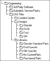
Earlier in the chapter, you looked at a sample job-based directory structure. Now, consider a directory structure for a product-type-based directory structure to serve customers in the automotive industries. Create a directory structure.
- Solution
Compare your directory structure with the one shown here. Do you have clear paths for support, data, and library files? Have you made it easy to locate parts? Does your structure support unique file and folder names?
- Create efficient search paths
Keep your search paths isolated. For instance, keep libraries in the library path, data in the project path, and so on. Organize and group your library parts into logical folders without duplication. Make it easy to find and maintain unique parts.
- Master It
Consider the location of the libraries in the following directory structure. How is this structure inefficient? Why is it more likely that duplicate parts will be created? How would you improve the search paths in this directory structure?
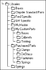
- Solution
Locating reusable library files in the data area makes them difficult to find, could lead designers to believe that the parts are intended to be edited, and will slow search and file resolution functions. For example, a designer working on optical components might not realize that the hex screw she's looking for has been filed away under in the motor parts area, buried in a gear library, which was filed in the Springs library. If the library were in the library path with other fasteners, the designer would not need to waste time re-creating the part, pulling a part number, and so forth. To improve efficiency, all libraries should be organized according to the type of part that should be located in that folder.
- Understand how Inventor uses data, library, and Content Center files
Your project file is an XML file that lists the locations and functions of each search path. Part loads and searches begin in the library search path, then move to the local workspace, and finally move to any workgroups. Keep your paths simple to reduce search and load times. Use library files to share designs and automatically protect parts and assemblies from inadvertent revision.
- Determine the best project type for your work
Project types include single-user projects, which are single-seat or single-designer projects, and Vault projects, which are single- or multiple-designer workflows to track work, maintain version control, and facilitate design reuse.
- Master It
For a complex product that will be worked on by several design teams and updated twice a year for the next five years, which project type would you choose?
- Solution
The best choice would be a Vault project given the number of revisions, engineering change orders, and updates anticipated and the fact that multiple design teams will work on the project. A single-user project would require that design team members work sequentially, vastly increasing the design time.
- Create single- and multiuser projects
Use the Inventor Project Wizard. Customize the default settings for your work. Include only the paths and files you expect to use. You can always add more later as needed. Use a master project if you frequently create similar projects.
- Master It
Why not include every library and data file in your project? What is the benefit of including a master project file?
- Solution
Limiting the files and library/data paths you include in your project reduces part and assembly loading, searching, and file resolution times. Using an include file to add a master project file to your project automatically sets the project configuration to preset values from the master project. This ensures consistent projects and saves project setup time.
Chapter 3: Sketch Techniques
- Set up options and settings for the sketch environment
Understanding the settings and options that apply to the sketch environment is an essential first step in working with Inventor.
- Master It
You want to configure your own set of options and settings for your sketch environment and then back them up and/or distribute them to other workstations. How would you do this?
- Solution
You configure the options and settings by going to the Get Started tab and selecting Application Options and then clicking the Sketch tab. Click the Export button to save the settings as an .xml file.
- Create a sketch from a part file template
Creating a sketch in a blank template file is the fundamental step in creating 3D parametric models. You will use this basic step to start most of your part designs.
- Master It
How would you capture the intent of your design when creating a base sketch for a new part?
- Solution
Use a combination of lines, arcs, and geometry as well as sketch constraints and dimensions to properly constrain your sketch. You can then use this sketch to create a base feature for your part.
- Use sketch constraints to control sketch geometry
Understanding what each sketch constraint does when applied will allow you to determine when to use each type. Recall that often more than one constraint will work in any given situation.
- Master It
How would you create a sketch that allows you to test "what if?" scenarios concerning the general shape and size of your part?
- Solution
First ensure that your sketches are properly constrained. Sketches that are properly constrained are needed to allow you to experiment with your dimensional parameters by changing values and testing "what if?" scenarios. If the sketch geometry is not properly constrained, then changes to dimensions may create unpredictable results.
- Master general sketch tools
Learning the features and tricks of the sketch tools will allow you to master Inventor sketching.
- Master It
You are given a print of mixed units to work from and need to enter dimensions exactly as they are on the print. You understand that you can enter any dimensions in any unit simply by adding the correct suffix. But how would you create a radius dimension on a circle or a dimension from the tangents of a slot?
- Solution
Recall that you switch between variant dimension solutions such as diameter to radius simply by right-clicking after having selected the geometry. You can also get alternate dimension solutions by selecting different parts of the same geometry. For instance, selecting a line and then almost anywhere on a circle will give you a dimension from the center point of the circle to the line, whereas selecting a line and the tangent quadrant point of the circle will give you a dimension from the tangent point of the circle and the line.
- Create sketches from AutoCAD geometry
You can use existing AutoCAD files to create a base sketch for an Inventor model of the same part.
- Master It
You have many existing 2D AutoCAD drawings detailing legacy parts. You want to reuse these designs as you convert to 3D modeling. How would you proceed?
- Solution
You can copy and paste selected geometry from AutoCAD directly into an Inventor sketch and then turn it into a solid model. Keep in mind that the results are dependent on the accuracy of the original AutoCAD data.
- Use 3D sketch tools
Much of working with a 3D parametric modeler can be done by sketching in a two-dimensional plane and then giving depth to the sketch to create 3D features. However, sometimes you need to create paths or curves that are not planar. In those cases, you use the 3D sketch tools.
- Master It
You know the profile of a complex curve as viewed from the top and side views. How would you create a 3D sketch from this data?
- Solution
Start by creating a separate 2D sketch for both the top and side views of the curve. Then create a 3D sketch and use the 3D Intersection Curve tool to find the intersecting curve.
Chapter 4: Basic Modeling Techniques
- Set application options and settings for part modeling
Understanding the settings and options that apply to the modeling environment is essential for getting the results you want from Inventor.
- Master It
You want to configure your options and settings for your sketch environment and then back them up and/or distribute them to other workstations. How would you go about doing this?
- Solution
You will first configure the options and settings by clicking Application Options on the Get Started tab, and then selecting the Sketch tab in the Application Options dialog box. Then use the Export button to save the settings as an
.xmlfile.
- Create basic part features
In this chapter, you learned how to plan a workflow that allows you to create stable, editable parts that preserve the design intent.
- Master It
You need to create a fairly complex part consisting of many extrusions, revolves, sweeps, or lofts. In addition, you will need to create holes, fillets, chamfers, and other part modifiers. This part may need significant modification in the future by you or by other designers.
- Solution
Determine how this part will be manufactured. Think about how the part might be designed to minimize production costs, while still fulfilling the intent of the design, by determining how many machining operations will be required. Determine the design intent of this part and how your approach will affect stability and any future edits or modifications.
- Use the Extrude tool
The Extrude tool is one of the most common feature tools in the Inventor modeling tool set. Understanding the options and solutions available in this tool will prove useful throughout your designs.
- Master It
Imagine you need to create an extruded feature but don't know the exact length; instead, you know the extrude will always terminate based on another feature. However, the location of that feature has not been fully determined just yet.
- Solution
Use the Extrude To option and extrude the feature profile to a face or work plane of the other feature. Then as you determine the location of the other feature and make adjustments, your extrusion will update as well.
- Create revolved parts and thread features
Creating revolved features and parts in Inventor can often resemble the creation of turned part and features in the real world. Applying thread features to a cylindrical face allows you to specify threads without having to actually model them.
- Master It
Let's say you have a part that you intend to fabricate on a lathe. Although you could create the part with a series of stepped circular extrusions, it occurs to you that the Revolve tool might work also.
- Solution
Oftentimes it may make sense to create a base extrusion from an extruded circle and then use the Revolve tool to create revolved cuts. This allows you to design both the stock material and the cut features with the intent of the design in mind, anticipating changes that might occur. You can then use the Thread tool to apply threads to any features requiring them.
- Create work features
Using work features, work planes, work axes, and work points enable you to create virtually any part or feature. Work features are the building blocks for sketch creation and use.
- Master It
Your design will require creating features on spherical and cylindrical faces. You need to precisely control the location and angle of these features.
- Solution
Using existing origin features, created model features and edges, sketch objects, and other existing geometry within the file will permit you to create parametric work features as the basis for additional geometry creation.
- Use the Fillet tool
The Fillet tool has a great deal of functionality packed into it. Taking the time to explore all the options on a simple test model may be the best way to understand all the options.
- Master It
You are trying to create a series of fillets on a part. You create four sets of edge selections to have four different fillet sizes, but when you attempt to apply them, you receive an error stating that the feature cannot be built.
- Solution
Sometimes the creation of multiple fillet sizes combined into one feature is not the way to go. Instead, identify the edges that will "compete" for a common corner, particularly where they differ in radius size, and create these fillets as individual fillet features. This allows Inventor to solve the corner in steps and makes the results more robust and less ambiguous.
- Create intelligent hole features
Although you can create a hole in a part by sketching a circle and extrude cutting it, this is typically not the recommended approach.
- Master It
You need to create a part with a series of various-sized holes on a plate. You would like to lay out the hole pattern in a single sketch and then use the Hole tool to cut the holes to the sizes required. However, when you select the From Sketch option in the Hole tool, it selects all of the holes, so you're thinking you must need to sketch out the hole pattern as circles and then use the Extrude tool to cut them out.
- Solution
Using the Extrude tool is not the way to go. Instead, create a sketch on the face of the plate, and use center points to mark the hole centers. Dimension each center point in place, and then start the Hole tool. Hold down Ctrl to deselect the center points for holes of a different size, and then create the hole feature for the first set of holes. Locate your sketch in the browser, right-click it, and choose Share Sketch. Then use the Hole tool to place the next size holes.
- Bend parts
You can bend a portion of a part after you define a bend line using a 2D Sketch line. You can specify the side of the part to bend, the direction of the bend, and its angle, radius, or arc length.
- Master It
You need to create a model of a piece of rolled tube and would like to specify the bend direction, but when you use the direction arrow, you get a preview in only one direction.
- Solution
Use a work plane to create a sketch in the middle of the part and then sketch the bend line on that work plane. This will allow you to specify either direction for the bend.
Chapter 5: Advanced Modeling Techniques
- Create complex sweeps and lofts
Complex geometry is created by using multiple work planes, sketches, and 3D sketch geometry. Honing your experience in creating work planes and 3D sketches is paramount to success in creating complex models.
- Master It
How would you create a piece of twisted flat bar in Inventor?
- Solution
Create the flat bar profile in a base sketch. Then create a work plane offset from the original sketch the length of the bar. Create the profile sketch on this work plane at a rotated orientation to match the degree of twist needed. Create a 3D sketch, and connect the corners of the first profile to the appropriate corners of the second profile. Use the Loft command to loft from one profile to the other, using the 3D sketch lines as rails, to produce the twisted part.
- Work with multi-body and derived parts
Multi-body parts can be used to create part files with features that require precise matching between two or more parts. Once the solid bodies are created, you can create a separate part file for each component.
- Master It
What would be the best way to create an assembly of four parts that require features to mate together in different positions?
- Solution
Create the parts in a multi-body part file, and subtract material from one part based on the profile of the other. Consider creating the first two of the parts in one multi-body part file and the other two in another multi-body part file in order to keep the files as simple as possible. You can also derive the first multi-body part into the second for better control.
- Utilize part tolerances
Dimensional tolerancing of sketches allows the checking of stack-up variations within assemblies. By adding tolerances to critical dimensions within sketches, parts may be adjusted to maximum, minimum, and nominal conditions.
- Master It
You want to create a model feature with a deviation so that you can test the assembly fit at the extreme ends of the tolerances.
- Solution
Use the Parameters dialog box to set up and adjust tolerances for individual dimensions. In the Parameters dialog box, set the tolerance to the upper or lower limits for the part, and then update the model using the Update button. Check the fit of the feature against its mating part or parts in the assembly environment, and then edit the part to set it back to the nominal once done.
- Understand and use parameters and iProperties
Using parameters within files assist in the creation of title blocks, parts lists, and annotation within 2D drawings. Using parameters in an assembly file allows the control of constraints and objects within the assembly. Exporting parameters allows the creation of custom properties. Proper usage of iProperties facilitates the creation of accurate 2D drawings that always reflect the current state of included parts and assemblies.
- Master It
You want to create a formula to determine the spacing of a hole pattern based upon the length of the part.
- Solution
Set up a user parameter that calls the part length and divides by the number of holes or the spacing, and then reference this user parameter in the hole pattern feature.
- Troubleshoot modeling failures
Modeling failures are often caused by poor design practices. Poor sketching techniques, bad design workflow, and other factors can lead to the elimination of design intent within a model.
- Master It
You want to modify a rather complex existing part file, but when you change the feature, errors cascade down through the entire part.
- Solution
Position the end-of-part marker just under the feature you intend to modify. Then move it back down the feature tree one feature at a time, addressing each error as it occurs. Continue until all features have been fixed.
Chapter 6: Sheet Metal
- Take advantage of the specific sheet-metal features available in Inventor
Knowing what features are available to help realize your design can make more efficient and productive use of your time.
- Master It
Of the sheet-metal features discussed, how many require a sketch to produce their result?
- Solution
Five sheet-metal features consume a sketch: Contour Flange, Face, Cut, Punch, and Fold. Since Inventor has well-established paradigms for how sketches can be manipulated, knowing which features consume sketches may allow you to develop designs that are flexible and parametrically configurable.
- Understand sheet-metal templates and rules
Templates can help get your design started on the right path, and sheet-metal rules and associated styles allow you to drive powerful and intelligent manufacturing variations into your design; combining the two can be very productive as long as you understand some basic principles.
- Master It
Name two methods that can be used to publish a sheet-metal rule from a sheet-metal part file to the style library.
- Solution
Rules and styles can be published or written to the style library either from Inventor or by using the Style Management Wizard (the harvester). Using the native Inventor method, right-clicking a given rule/style produces a command called Save To Style Library. Using the harvester, you can select a specific file and add its style information to your existing style library or create a new one.
- Author and insert punch tooling
Creating and managing Punch tools can streamline your design process and standardize tooling in your manufacturing environment.
- Master It
Name two methods that can be utilized to produce irregular (nonsymmetric) patterns of punch features.
- Solution
Sketch center marks can be patterned within the insertion sketch as a symmetric array. During Punch tool insertion, the Centers control on the Geometry tab can be used to deselect center marks where you want a tool to be placed. The feature-patterning tools can also be used to create irregular patterns after a punch feature has been created. You can do this by first creating a symmetric pattern of punch features, then expanding the child pattern occurrences in the feature browser, and finally individually suppressing them. Both methods prevent the feature from being displayed in the folded and flat pattern as well as omit the Punch tool information in the flat pattern punch metadata.
- Utilize the flat pattern information and options
The sheet-metal folded model captures your manufacturing intent during the design process; understanding how to leverage this information and customize it for your needs can make you extremely productive.
- Master It
How can you change the reported angle of all your Punch tools by 90 degrees?
- Solution
The flat pattern's orientation infers a virtual x-axis for punch angle calculation, so rotating the flat pattern by 90 degrees will change all the punch angles by the same amount. The flat pattern can also affect the bend and punch direction (up or down) by flipping the base face, and reported bend angles can be changed from Bending Angle to Open Angle by changing options in the Bend Angle tab of the Flat Pattern Definition dialog box.
- Understand the nuances of sheet-metal iPart factories
Sheet-metal iPart factories enable you to create true manufacturing configurations with the inclusion of folded and flat pattern models in each member file.
- Master It
If you created sheet-metal iPart factories prior to Inventor 2009, any instantiated files contain only a folded model. Name two methods that you could use to drive the flat pattern model into the instantiated file.
- Solution
Once you have opened, migrated, and saved a legacy sheet-metal iPart factory, you can decide between two methodologies for obtaining the flat pattern model within your instantiated files: push or pull. The push method is accomplished from within the iPart factory by using the context menu command, Generate Files, which is associated with the member filename. This method pushes out a new definition of the member file including the flat pattern model. The pull method requires you to using the Inventor command, Rebuild All, followed by saving the factory file. Now that the factory has been rebuilt, any time you open one of the instantiated files associated with the factory, it will see that it's out-of-date and will trip the update flag. Selecting Update will pull the flat pattern model into the instantiated member file.
- Model sheet-metal components with non-sheet-metal features
Inventor doesn't always allow you to restrict yourself to sheet-specific design tools; understanding how to utilize non-sheet-metal features will ensure that your creativity is limitless.
- Master It
Name two non-sheet-metal features that can lead to unfolding problems if used to create your design.
- Solution
As discussed in the chapter, Loft and Shell can lead to numerous problems during unfolding because of nondevelopable curvature introduced by Loft and nonuniform thickness introduced by Shell.
- Work with imported sheet-metal parts
Understanding the way in which Inventor accomplishes unfolding as well as how to associate an appropriate sheet-metal rule are keys to successfully working with imported parts.
- Master It
Name the one measured value that is critical if you want to unfold an imported part.
- Solution
The measured sheet thickness is the most important geometric measurement in an imported sheet-metal part. Ensuring that the thickness of your imported part matches the active Thickness parameter means the difference between success and frustration. Although you can change the active rule (or create a new one) to match all the geometric conditions of your imported part, these will affect only new features or topology that you introduce; Thickness is the key.
- Understand the tools available to annotate your sheet-metal design
Designing your component is essential, but it's equally important to understand the tools that are available to efficiently document your design and extract your embedded manufacturing intent.
- Master It
What process is required to recover flat pattern width and height extents within your Drawing Manager parts list?
- Solution
By creating custom iProperties within your sheet-metal part file set equal to <FLAT PATTERN LENGTH> cm and <FLAT PATTERN WIDTH> cm, flat pattern extents can be referenced by your parts list by adding these new properties using the Column Chooser command. To make this process more efficient, you can predefine the custom iProperties in your sheet-metal template file, and the custom properties can be authored into a custom Drawing Manager parts list template for quick application.
- Harvest your legacy sheet-metal styles into sheet-metal rules
Using the harvesting utilities provided, you can extract your legacy sheet-metal styles and publish them into style library sheet-metal rules, pre-associated to material styles, sheet thickness values, and sheet-metal unfold rules.
- Master It
How can you extract sheet-metal style information from a legacy part files or template files for the purpose of publishing it with a Sheet Metal Rule?
- Solution
By launching the Style Management Wizard application (also known as the harvester) from Program Files

As a reminder, although it is possible to harvest sheet-metal rules that contain references to model parameters and linked external files, this is simply a result of the harvester's inability to detect these conditions. The extracted rule information will be broken, and the rule will not be usable. By default, the sheet-metal document will leverage some programmatic values to keep your model from being corrupted, but once you open the Style And Standard Editor dialog box, you will see errors that must be resolved. To avoid this situation, it is recommended that you preview the contents of files before utilizing them for harvesting. If you need to be able to reference model parameters or external files to drive your sheet-metal rule, define these rules within your template file.
Chapter 7: Part and Feature Reuse
- Create and modify iParts
iParts are the solution to creating parts that allow for an infinite number of variations without affecting other members of the same part family already used within your designs.
- Master It
You use a purchased specialty part in your designs and would like to create the many size configurations that this part comes in ahead of time for use within assembly design.
- Solution
Create or use an existing model, and edit the parameter list to name specific parameters to logical names. Add the configuration table by creating an iPart from this model. Configure the parameters in the table and add rows according to variations needed. And finally, test the newly created iPart by inserting all variations of the part into a blank assembly.
- Create and use iFeatures and punches
Creating a library of often-used features is essential to standardization and improved productivity within your design workflow.
- Master It
You want to be able to place common punches, slots, and milled features quickly, rather than having to generate the feature every time.
- Solution
Extract iFeatures from existing standard and sheet-metal part features, and place them in user-defined folders within the
Catalogsubfolder. Using your custom-created iFeatures as well as standard iFeatures, practice placing them into your designs to see how they behave and how they can be modified. Finally, once the iFeatures or punches have been proven to work as expected, use them to quickly place common features in your production designs.
- Copy and clone features
You do not have to create iFeatures in order to reuse various part features in your designs. If a part feature will have limited use in other designs, it is often better to simply copy it from part to part or from face to face on the same part.
- Master It
You need to reuse features within a part or among parts. You consider iFeatures, but realize that this feature is not used often enough to justify setting up an iFeature.
- Solution
Right-click the existing feature, and choose Copy. Determine whether dependent and independent features such as fillets and chamfers need to be copied as well, and then paste the feature onto another face in the same part. Or open a different part file and paste onto a selected face. Copying between two parts is called cloning.
- Link parameters between two files
Linking design parameters between two or more files allows you to control design changes from a single source, making it easy to update an entire design from one file.
- Master It
You want to specify the overall length and width of a layout design in a base part and then have other components update as changes are made to this part.
- Solution
From the other component files, open the parameter editor, use the Link button to specify the source file, and then choose which parameters to link. You can then call those linked parameters into the sketch and feature dimensions of the other components in your design.
- Configure, create, and access Content Center parts
Content Center provides a great opportunity to reuse database-created geometry within assemblies and within functional design modules. The Content Center Editor provides the means to add custom content into Content Center. You can create and add custom libraries to your current project file.
- Master It
You would like to change the part numbers in some Content Center components to match the part numbers your company uses. You would also like to add proprietary components to Content Center.
- Solution
Create a custom Content Center library. Configure your project file to include your newly created read/write Content Center library. Utilize the Content Center Editor to create new categories within your custom Content Center library. Convert a part or an iPart to a Content Center component using the Publish option.
Chapter 8: Assembly Design Workflows
- Organize designs using structured subassemblies
Subassemblies add organization, facilitate the bill of materials, and reduce assembly constraints; all this results in better performance and easier edits. One of the habits of all Inventor experts is their effective use and understanding of subassemblies.
- Master It
You need to hand off an accurate BOM for finished designs to the purchasing department at the end of each design project.
- Solution
Organize parts in subassemblies in a real-world manner matching the way that components are assembled on the shop floor. Use Phantom assemblies when structuring parts merely for the purpose of reducing assembly constraints. Set assemblies as Purchased or Inseparable when you want multiple components to appear as a single item in the BOM. Export the BOM from the assembly to an Excel spreadsheet or other intermediate format to give to purchasing.
- Use positional reps and flexible assemblies together
Often you may need to show a design in various stages of motion to test interference and/or proof of concept. Copying assemblies so that you can change the assembly constraints to show different assembly positions can become a file management nightmare. Instead, use flexible subassemblies and positional representations.
- Master It
You need to show your assembly in variations dependent upon the position of the moving parts and the task the machine is accomplishing at given stages of its operation.
- Solution
Leave subassemblies underconstrained if they have parts that determine their position based on the relationships with parts within another subassembly. Set them to Flexible to allow them to be mated to other parts and used in different positions within the same top-level assembly. Create positional representations to show the design in known kinematic states, such as fully opened, closed, opened at a given angle, and so on. As an added benefit, animating assemblies in Inventor Studio is very simple when positional representations have been set up in the model.
- Copy designs
Because of the live linked data that exists in Inventor assemblies, using Windows Explorer to copy designs and rename parts is difficult and often delivers poor results. Using the tool provided in Inventor will allow you to copy designs and maintain the links between files.
- Master It
You need to duplicate an existing design in order to create a similar design.
- Solution
Use the Copy Components feature in the assembly environment to copy designs and choose which parts to copy and rename, reuse, or omit from the new design. Use Autodesk Vault to take it to the next level and include all the 2D drawings in the copied design.
- Substitute a single part for entire subassemblies
Working with large assemblies, particularly where large, complex assemblies are used over and over as subassemblies within a top-level design, can tax almost any workstation if not approached in the correct manner.
- Master It
You would like to swap out a complex assembly for a simplified version for use in layout designs or to use in large assemblies in an attempt to improve performance.
- Solution
Create LOD representations to suppress components when not in use during the design cycle. Create single substitute parts from large complex assemblies to be used as subassemblies within the design. Enjoy the benefits of referencing fewer files while maintaining an accurate bill of materials.
Chapter 9: Large Assembly Strategies
- Select a workstation
Having the right tool for the job is the key to success in anything you do. This is true of selecting a large assembly workstation. You have learned that for optimal performance you should strive to keep your system working in physical memory (RAM).
- Master It
You notice that your computer runs slowly when working with large assemblies and want to know whether you should consider a 64-bit system.
- Solution
Evaluate the amount of time you spend working on large assemblies and the amount of that time you spend waiting on your workstation in order to decide whether your system is adequate. Monitor your RAM usage, and decide whether upgrading to 64-bit system is a good solution for your needs. You should plan for hardware upgrades in your budget to make them more manageable.
- Adjust your performance settings
You have learned that there are many settings in Inventor and in Windows that you can use to configure the application to work more efficiently with large assemblies.
- Master It
You want to make your current workstation run as efficiently as possible for large assembly design.
- Solution
Disable the unneeded Windows visual effects and discontinue the use of screen savers, large resolution screen sizes, and desktop wallpapers. Learn the location of the Application Options settings within Inventor that will provide performance gains.
- Use best practices for large assembly
Knowing the tools for general assembly design is only half of the battle when it comes to conquering large assemblies. Understanding the methods of large assembly design and how they differ from a general assembly design is a key to success.
- Master It
You want to create adaptive parts so that you can make changes during the initial design stage and have several parts update automatically as you work through the details. But you are concerned about how this will adversely affect your assembly performance.
- Solution
Create adaptive relationships between parts as you normally would, but ensure that the adaptivity is turned off once the initial design is done. If the parts require an update, turn adaptivity back on, make the edits, and then turn adaptivity back off.
- Manage assembly detail
Inventor includes several tools to help manage assembly detail so that you can accomplish your large assembly design goals.
- Master It
You want to reduce the number of files your large assembly is required to reference while you are working on it and yet maintain an accurate bill of materials.
- Solution
Use substitute LOD representations to derive a subassembly into a single part file. Place multiple instances of the subassembly into the top-level assembly at the substitute level of detail.
- Simplify parts
Creating highly detailed parts may be required for generating production drawings or Inventor Studio renderings, but using those high-detail parts in large assemblies may have an adverse affect.
- Master It
You want to create a lower level of detail part file for common parts to be reused many times over in your large assemblies but are concerned about managing two versions of a part.
- Solution
Create an embedded link between the two versions so that you can easily locate and access the other version if the first version requires an edit.
Chapter 10: Weldment Design
- Select and use the right weldment design methodology
We have shown you three weldment design methodologies. Before starting on any weldment design, it is imperative to keep the documentation, interference analysis, mass properties, and other design criteria in perspective and select the right design methodology.
- Master It
What is the right weldment strategy for you? If you don't need to document the weldment design stages, you could consider the part files and part features methodology or the weldment assembly and derived methodology. With the weldment assembly methodology, you get to document the different stages of weldment design and reap the benefits of any new enhancements.
- Solution
Talk to your machine shop, and then choose the right one that best suits you. Use the weldment assembly design methodology if you can't decide.
- Create and edit weld preparations and machining features
Following the weldment methodology, you need to plan on creating the gaps needed (weld preparations) to deposit the weld beads. You need to create post weldment machining features that go through the weld beads.
- Master It
Where can you find preparation and machining features, and when do you use them? Weld preparations and machining features are similar to part modeling features. Based on the weld bead shape needed, you need to plan for creating the preparations in advance. Once the welds are done, you need to create the features for the machining processes.
- Solution
Double-click the Preparations or Machining command in the assembly Model browser to go into those environments. Chamfer and Move Face are most commonly used. Most groove welds require some kind of weld preparations.
- Create and edit different kinds of weld beads such as cosmetic, fillet, and groove
We have described the relative advantages and disadvantages of cosmetic and solid weld beads. Weldment design involves the optimal mix of these weld beads based on needs and requirements.
- Master It
You need to create the weld annotations only in drawings, without any need to create them in the model. You have weld subassemblies that need only lightweight representation in both the model and drawings. In situations involving accurate interference and mass properties, you need accurate weld beads. The question is: What type of weld beads should you use?
- Solution
Double-click Welds in the assembly Model browser, and choose the desired weld bead type. For a lightweight representation with no interference and accurate mass properties, use cosmetic welds. For interference and accurate mass properties, use the solid representation. Use a combination of fillet and groove welds as needed to generate the desired weld bead shape. Use the split technique in cases where you need precise control. Observe that you can use a single weld symbol to call out multiple weld beads.
- Document weldment stages in drawings
Welds need to be documented in assemblies or drawings. It is important to show the different stages of weldment design in drawings to get a good idea of how to manufacture the weldment. You can use the drawing tools effectively to annotate the welds in drawings. This will help the welder understand the design intent better.
- Master It
What are the different tools used for weld documentation? You can annotate the welds in assemblies. If you prefer to document the welds in drawings, you could document the four stages of weldment design: as-assembled, as-prepped, as-welded, and as-machined stages in drawings. Besides, you could use other drawing manager tools to customize weld documentation.
- Solution
While creating a drawing view on the Model State tab of the Drawing View dialog box, select Assembly, Machining, Welds, or Preparation. Use the End Fill tool to customize the weld bead process shape. The Weld Caterpillars is another useful tool to show welds in a drawing.
- Generate and maintain a consistent BOM across welded assemblies, drawings, and presentations
You have been shown how to generate and maintain a consistent bill of materials for weldment assemblies and a parts list in drawings. Mark parts or assemblies as inseparable to designate them as weldments.
- Master It
How do you generate the BOM and parts list for your weldment? You can generate the bill of materials and mark the components as Inseparable. In the drawing, you generate the parts list for the weldment assembly.
- Solution
Click the BOM command in a weldment assembly. In the Structure column, you can set each part to be inseparable. Use the Parts List tool and appropriate table wrapping options to generate the parts list.
Chapter 11: Functional Design
- Use Inventor's Design Accelerators
Design Accelerators and Design Generators allow you to rapidly create complex geometry and the associated calculations that verify the viability of your design.
- Master It
Your design needs a bolted connection, but you are not certain about the number of bolts to use to ensure a proper connection.
- Solution
Use the Bolted Connection Generator to determine the optimum number of bolts for a given material and loading conditions.
- Use Inventor's Design Calculators
Design Calculators do not create any geometry, but they permit you to store the calculations in the assembly and repeat the calculation with different input values at a later time.
- Understand the interaction of these tools with Content Center
Some of the generators use content center, while others create custom geometry.
- Master It
You receive an error when you try to specify fasteners for a Bolted Connection.
- Solution
The Bolted Connection Generator requires Content Center. If you use Desktop Content, check your project file to make sure you have Content Center Libraries configured. If you use shared content, confirm that you are logged into the Content Center server.
- Develop best practices for using these tools
In this chapter, we explained how to use Design Accelerators in the best possible way by providing best practices and tips and tricks concerning the use of templates, exploring the benefits of using a particular type of calculation or connection method for a given scenario, and showing how to select the right material to do the job.
- Master It
You need to design a camshaft to activate an inlet valve that needs to respect a specific lift-over-time graph. You also want to reuse the design and slightly modify it for other similar cams like the exhaust valve.
- Solution
Use the Disc Cam Generator to design the shape of the cam; then use a template to export the design, import it, and reuse it for a new design.
- Master It
You want to design a compression spring that operates within very strict dimensional limitations and find a spring material that also satisfies the load requirements.
- Solution
Use the Spring Generator to select the combination of pitch, wire diameter, and material that withstands the applied force without becoming fully compressed.
- Master It
Your design needs a gear transmission between two shafts with a predefined position, and you want the gears to be separate components that need to be connected to the shaft.
- Solution
Use the Spur Gear Generator to construct the gears. Use the Key Connection Generator to connect the gears to the shafts.
Chapter 12: Documentation
- Create an exploded assembly view by creating a presentation
Presentation files are used to virtually disassemble an assembly so downstream consumers can better visualize the design. The explosion created in the presentation file can be referenced in an assembly drawing to complement nonexploded assembly views.
- Master It
Your assembly design is complex and contains many internal components that can't be visualized in traditional assembly drawing views.
- Solution
Create a new presentation file, reference an assembly, and tweak parts and subassemblies away from their constrained positions. Add as many tweaks as necessary to communicate the design affectively. You may choose to create several explosions in one presentation file to achieve this goal.
- Create and maintain drawing templates, standards, and styles
Inventor provides numerous methods to create, store, and use drawing templates and styles. Careful planning should be considered for how and where to manage these resources. Consideration must be given to how templates are deployed on your network and whether to use the style library.
- Master It
Rather than using one of Inventor's out-of-the box drawing settings, you need to set up a drawing template, a drafting standard, and annotation styles to conform to a particular international, industry, or company drafting standard.
- Solution
Use one of the drawing templates that are installed with Inventor, and reconfigure it to meet your or your company's requirements. Edit the drawing resources to customize your title block, border, and sketched symbols. Define annotation styles such as dimension and parts list styles, and determine how best to share them across your workgroup.
- Generate 2D drawing views of parts, assemblies, and presentations
The Drawing Manager environment in Inventor enables you to generate traditional 2D drafting views from your 3D solid models.
- Master It
You've used Inventor's modeling tools to generate parts and assemblies to meet your design criteria. Now you need to generate drawing views of this design so that it can be communicated to machinists, fabricators, and inspectors.
- Solution
Generate drawing views of your model using the Drawing Views panel in Inventor's Drawing Manager. Generate as many projected and cut views as necessary to fully communicate your design.
- Annotate drawing views of your model
Drawing Manager provides a rich set of dimensioning tools, special symbols, and tables that enable you to fully annotate part and assembly drawings conforming to several international drawing standards.
- Master It
Now that you've generated drawing views of your design, the views must be fully annotated in accordance with your company's or your customer's required drafting standard.
- Solution
Use the Drawing Annotation panel to place dimensions, tables, and symbols on your part or assembly views to fully communicate the design. Use styles to help create consistent drafting techniques and conformity to drafting standards.
Chapter 13: Inventor Tools Overview
- Take your models from Inventor to Autodesk Building Systems
If you frequently need to take your Inventor models to ABS, then AEC Exchange can help you in this process with three simple steps. Inventor provides a variety of ways to simplify the model and author it. Such models can be published in ABS.
- Create AutoLimits (design sensors)
You use AutoLimits to monitor design parameters in which you are interested.
- Master It
How many AutoLimits can you use in an assembly?
- Solution
Create the AutoLimits and set up their boundaries. Although technically the number of AutoLimits you can use in your model is unlimited, you should consider limiting the number of AutoLimits to around 10, in order to avoid impacting the performance of your model.
- Manage design data efficiently using Inventor tools
There are different tools for managing design data, which is typically distributed across part, assembly, and drawing files. You can associate Excel spreadsheets, text files, Word documents, and so on, with these tools.
- Master It
The Design Assistant keeps the file relationships while copying, renaming, and moving files. Whenever you are sending Inventor files to others, use Pack And Go, which hunts the file relationships down for you and then you can package it into a single ZIP file. You can delegate many of the tasks in Inventor to the Task Scheduler. You can propagate source drawing template information to several destination drawings using the Drawing Resource Transfer Wizard.
- Solution
In the Design Assistant, click the Manage button. Right-click the file in the Action column, and select Action. Right-click the file in the Name column, and select Change Name. Click Save Changes. Right-click the file in Windows Explorer to use Pack And Go. In the Task Scheduler, use the Create Task menu to create your task. In the Drawing Resource Transfer Wizard, select source resources, deselect any unwanted resources, and propagate the template information to destination drawings.
- Manage styles
You can use the Style Library Manager and the Style Management Wizard to organize your styles to keep them simple and clean.
- Master It
How do you manage your styles? Styles normally need to be copied, edited, and deleted. Use the Style Library Manager. How can you create a central repository of styles? How do you purge styles? Use the Style Management Wizard for these tasks.
- Solution
You can create a new style library using the Create New Style Library button in the Style Library Manager. You can copy styles by clicking Style Library 1 and then clicking Style Library 2. To delete styles, right-click the style in the Style Library Manager, and then rename or delete the style. You can harvest styles by adding files and then clicking Harvest Styles Into Target Style Library. You can select an existing style library or create a new library by clicking Start. You could also purge styles in a library by clicking Purge All Unused Styles From Files in the Style Management Wizard.
- Create expressions with iProperties
Property fields can be concatenated to produce desired customized information in BOM and parts lists.
- Master It
You can break down for example "stock size" of your parts to be used in your BOM with associativity to model parameters. You can create and manage expressions for iProperties.
- Solution
You can create expressions on the Summary, Project, Status, or Custom tab. Start with the = sign, and type in the text. To include parameters or iProperty names, include them in brackets. A detected expression is denoted by fx. You can create a template file with predefined expressions for iProperties to unify your parts list and other documentation.
- Measure in assemblies
Click the right Measure tool and selection filters to make measurements.
- Master It
How do you measure in assemblies? Once you set the selection filter, you make the selections and use the measurement helpers to get complex measurements.
- Solution
Use the measurement helpers to accumulate measurements. Click the correct selection filter in the assembly's environment to get the measurement between components, parts, or faces and edges.
- Give feedback to Autodesk
You can participate in the Customer Involvement Program (CIP). Customer error reporting (CER) helps Autodesk know about any issue you might experience.
- Master It
You have a repeatable crash that you suspect is related to a specific file, or a specific machine, and want to know if Autodesk can help you determine this.
- Solution
You can use the CER form to supply step by step information about repeatable issues and contact information, and then call reseller support or log a case with Autodesk through the subscription website. Autodesk can look up your CER based on the submittal time and contact information you entered.
Chapter 14: Exchanging Data with Other Systems
- Import and export geometry
In the design world today, you most likely need to transfer files to or from a customer or vendor from time to time. Chances are, the files will need to be translated to or from a neutral file format to be read by different CAD packages.
- Master It
You are collaborating with another design office that does not use Inventor. You are asked which you would prefer, IGES or STEP files.
- Solution
Request a STEP file over IGES when you have the choice. Take advantage of the extra intelligence related to assembly structure and filenames that can be retained in the STEP file format.
- Use Inventor file translators
Inventor offers native file translators for CATIA, Pro/ENGINEER, SolidWorks, Unigraphics, and other CAD file types. This allows you to access these file formats with Inventor and translate the files into Inventor files directly.
- Master It
You are a "job shop" and in the past have been required to maintain a copy of SolidWorks in addition to your copy of Inventor in order to work with customers who send you SolidWorks files. You would like to eliminate the cost of maintaining two software packages.
- Solution
Use Inventor to access the customer's files directly and convert them to Inventor files for your in-house use. Use Save Copy As to export the file back out as a SolidWorks file to send to the client for review. In this way you may be able to eliminate the need to maintain two software packages.
- Work with imported data
Using the construction environment in Inventor, you can repair poorly translated surface files. Often a file fails to translate into a solid because of just a few translation errors in the part. Repairing or patching the surfaces and promoting the file to a solid allows you to use the file more effectively.
- Master It
You download an IGES file from a vendor website, but when you attempt to use the component in your design, the surface data is found to have issues.
- Solution
Open the file and copy the surfaces to the construction environment. Use Stitch Surface to create composite surfaces, and identify the gaps in the surface data. Use the construction tools to delete, patch, and extend surfaces in order to close the gaps and promote the data to a solid. Before getting started on this, evaluate the amount of time required to repair the surface data. You may find that you can model the vendor component, by using catalog specs or by measuring an actual part, faster than you can repair some surface models.
- Work with Design Review markups
Design Review offers you and the people you collaborate with an easy-to-use electronic markup tool that can be round-tripped from Inventor. Design Review markups can be made on both 2D and 3D files.
- Master It
You want to use Design Review to communicate with vendors and clients in order to save time and resources, but you have found that others are unsure of what Design Review is and how to get it.
- Solution
Suggest using Design Review to the people you collaborate with and mention to them that this application is a free download. Send them the link to download the application and the online demonstration found in Design Review's Help menu. Continue to offer your collaborators the review material in PDF, DWG, or any other traditional file type in case they end up in a time crunch, but send them DWF files as well. If they use Internet Explorer 7, consider sending them DWFx files, and mention to them that they can open those files directly in their web browser.
Chapter 15: Frame Generator
- Work with frame files
Frame Generator puts all the members at the same level in the assembly.
- Master It
You have a frame that is built up in sections that are welded together. You need to document the manufacturing process.
- Solution
Use Demote to create subassemblies of frame members. Select the frame members in the browser. From the context menu, select Component
- Insert frame members onto a skeleton model
Frame Generator builds a skeleton model for the frame from the selected lines and edges.
- Master It
Since Frame Generator builds its own skeleton model, you don't have to build a master model before you start creating the frame. You can use sketches, surfaces, and model edges to insert frame members.
- Solution
Use layout sketches and surfaces to design the basic frame shape. Position the components that will be mounted to the frame in the assembly, and reference edges on the parts. As you make changes to the assembly, such as the overall size or the position of components, the frame will automatically update.
- Add end treatments to frame members
Frame Generator does not support end treatments on merged members.
- Master It
Let's assume you are building a stairway and the handrail has curved sections.
- Solution
You can handle this situation in several ways:
When you create the frame member, don't select the Merge option. This creates individual files for each segment. You can add end treatments to the end segments and document the details in the assembly drawing.
Create the sketches so the ends of the curved member terminate at the face of another member. If the mating member has a flat face, you don't need an end treatment.
Add short linear segments that aren't merged with the rest of the curved member. You can document that the length of the curved member does not include end treatments.
Manually create end treatments using part-modeling commands. Frame members are created as custom parts that can be edited.
- Make changes to frames
Inventor provides detailed frame member information.
- Master It
You need to determine the size and wall thickness of the tubing and make it either thicker or larger.
- Solution
Use the Frame Member Info tool to get the properties for the frame members. Then, you can use the Change tool to increase the wall thickness, increase the size, or select a different structural profile.
- Author and publish structural profiles
Frame Generator uses structural shapes from the Content Center.
- Master It
You need to add custom aluminum extrusions to the Content Center so Frame Generator can access them.
- Solution
Use the Structural Shape Authoring tool to prepare the parts for publishing. Use the Publish Part tool to add the parts to the Content Center.
- Create BOMs for Frame Generator assemblies
Frame Generator has special parameters for frame members.
- Master It
You need to add the profile dimensions and the length to the Description field.
- Solution
Use the BOM expression builder to add the Stock Number and G_L parameters to the Description field.
Chapter 16: Inventor Studio
- Create and manage surface, lighting, and scene styles
Creating your own more realistic styles is often the difference between a rendering that looks kind of real and one that is photorealistic.
- Master It
You need to create a surface style that portrays black, bumped plastic.
- Solution
Here is the preferred way to create a new surface style:
Copy the Black surface style, giving the new style an appropriate name, such as Plastic (Black – textured).
On the Diffuse tab, click Use Texture Image.
In the list of images, select one of the Plastic image textures.
On the Bump tab, click Same As Texture, and set the percent value to 50 percent.
Save and apply the texture to the component.
Here is the preferred way to create a new lighting style:
Copy the lighting style containing most of what your new style needs, giving the new style an appropriate name.
On the various tabs, modify the lighting parameters.
Click OK.
Here is the preferred way to create a new scene style:
Copy the scene style that has similarities to the new style, giving the new style an appropriate name.
On the various tabs, modify the scene parameters.
Click OK.
- Create and animate cameras
Although static camera animations are a common part of any animation, creating and animating cameras give your renderings a much more professional feel. You need to create a camera and animate it.
- Master It
You decide to use the most expedient means to capture camera keyframe positions.
- Solution
To create a new camera, do the following:
Use the view orientation tools to position the view to show what the camera would see in the first frame.
Right-click, and select Create Camera From View.
To animate the camera, do the following:
In the Animation Timeline window, in the drop-down list, select the new camera by name.
In the Animation Timeline window, set the time slider to the time position representing when you want the camera to be in another location.
In the Scene browser, right-click the new camera node, and click Animate Camera.
In the graphics region, use the view orientation tools to position the view to show what you want at that time position.
In the Animation Timeline window, click Add Camera Action.
Repeat as needed.
- Start new animations, modify animations, and use the various animation tools
Animating your assemblies so that the function of the mechanism is showcased is often the purpose of an assembly animation.
- Master It
You have an existing animation but want to do a variation on it. You want to copy and edit an existing animation.
- Solution
Copy the animation:
In the Scene browser, expand the Animations node.
Right-click the animation for which you want to make a variation, and click Copy Animation.
Right-click the Animations folder, and click Paste Animation.
The Animations folder populates a new animation based on the selected animation.
Modify the animation:
Right-click the new animation, and click Activate.
In the Animation Timeline window, make modifications to actions as needed.
Add new actions as needed using the animation commands.
- Use multiple cameras to create a video production of your animation
Video Producer provides the means to combine camera shots into a single video output.
- Master It
You have created several cameras, animated and static, and want to make a composite animation.
- Solution
Do the following:
In the Scene browser, expand the Productions node.
If no production exists, right-click the Productions node, and click New Production.
The cameras are loaded into the Video Producer window and ready for use.
Drag and drop shots into the timeline, and set their parameters.
Drag and drop the desired transitions between the shots.
- Use props to enhance your scene
Inventor assemblies can be combined with other components to create a more realistic scene for rendering.
- Master It
You have completed a design and want to render a realistic image of it in its working environment.
- Solution
Do the following:
- Render realistic and illustrative images
Inventor provides the means to render both realistic and illustrative images.
- Master It
With your new product nearing completion, the marketing department has asked for rendered images for marketing collateral and technical documents such as white papers.
- Solution
To create a realistic rendering, do the following:
Prepare the scene with what you want to render.
Click the Render Image command.
In the Render Image dialog box, select Realistic as the render type.
Specify the camera, lighting, and scene styles to use.
Click Render.
To create an illustration rendering, do the following:
Prepare the scene with what you want to render.
Click the Render Image command.
In the Render Image dialog box, select Illustration as the render type.
Specify the camera, lighting, and scene styles to use.
On the Style tab, specify the appropriate settings for your rendering.
Click Render.
- Render animations and video productions
Inventor provides the means to render animations and video productions.
- Master It
You've created a wrapper assembly and set up the scene with cameras, lighting, and a scene style. Now you want to render an animation for design review and a video production for a multidiscipline review or marketing use.
- Solution
To render the animation, do the following:
In the Scene browser, select and activate the animation you want to render.
Deactivate any active production.
Remember: When a production is active, it is the render target. To render a single animation, you must deactivate any active production.
In the Studio tool panel, click Render Animation.
Specify the various styles to use and the render type.
Specify the output file type and other parameters.
Render the animation.
To render a production, do the following:
In the Scene browser, select and activate the production you want to render.
If you have not completed composing the production, you should do so.
In the Studio tool panel, click Render Animation.
Specify the various styles to use and the render type.
Specify the output file type and other parameters.
Render the animation.
Chapter 17: Stress Analysis and Dynamic Simulation
- Set up and run Stress Analysis simulations
Oftentimes you may find yourself guessing at what impact a change to your design might have on the strength and overall integrity of your part. Questions such as "Can I make this part a bit lighter?" or "Can I move this cutout closer to the edge?" become key to the success of your design.
- Master It
Set up a parameter study in your model to explore the consequences of editing features and their locations. Nominate all the crucial parameters to the table, and then create the configuration simulations for all of the combinations.
- Solution
Interpret the results of the parameter study, looking for the configuration that promises to exhibit the results that come closest to your goals such as a target safety factor. Interrogate the various configurations to see which ones would be considered underbuilt and overbuilt, and then determine why. Understanding what works and doesn't work will allow you to get closer to the target from the beginning of the design process next time.
- Set up and run Dynamic Simulation simulations
When you find yourself working out the details of a design with many moving parts, consider using the Dynamic Simulation tools early in the process to prove what will or will not work before going forward.
- Master It
Even before the assembly is complete, switch over to the Dynamic Simulation environment, and create assembly constraints in the simulation. Test the motion as you build the parts, and attempt to understand how contact will occur from the beginning.
- Solution
Enable the automatic assembly constraint option so that as you create constraints, standard joints are automatically created. Use the input grapher to design in the fourth dimension (time), understanding how a mechanism will or will not work as you go through the stages of its operation.
- Export results from the Dynamic Simulation environment to the Stress Analysis environment
Often when setting up a stress analysis simulation you are guessing at what the loads might be based on rough calculations. As you make changes to the design, those calculations become out-of-date and therefore invalid.
- Master It
Use the Dynamic Simulation tools to determine the force exerted on one part by another. When the parts are modified, the load calculations will automatically update based on the mass properties.
- Solution
Export the FEA information for the crucial time steps from the Dynamic Simulation environment into the Stress Analysis environment, and run the simulation. This helps keep your calculations both accurate and up-to-date.
Chapter 18: Routed Systems
- Create routes and runs
Using routed systems tools allows you to quickly define many different routes types in order to check for clearance and fits within a design, all while creating a bill of materials that can be used downstream in the manufacturing process.
- Master It
How can you extract a bill of materials from a routed systems assembly?
- Solution
BOM data can be extracted from a routed systems assembly in the same way that it is in a standard assembly file, by using the Bill Of Materials button on the Assemble tab. Keep in mind that routed systems designs, by default, consist of subassemblies, which allows for greater control over the BOM data you extract.
- Author a tube and pipe component
To create your own fittings, coupling, and so on, to be used within tube and pipe design, you need to first author it for use with the tube and pipe tools.
- Master It
How can you set the depth at which pipe, tube, or hose segments are inserted into a fitting?
- Solution
The pipe engagement is set during the tube and pipe component authoring process to determine how deep the segment will fit into the fitting. For butt weld–style components, the engagement is set to 0, since there is no insertion. Content Center components have the engagement positioning already set.
- Author an electrical component
To create your own electrical connector components be used within cable and harness designs, you need to first define pins within the parts.
- Master It
How can you create a family of electrical connectors with varying numbers of pins?
- Solution
First use the Place Pin or Place Pin Group tools to add the maximum number of pins to the connector part. Then convert the part to an iPart. In the iPart Author dialog box, use the Work Features tab to include only the pins required for each pin variation.
- Create and document cable and harness assemblies
Cable and harness assemblies are created using a specific subassembly and part structure. Each harness is contained in a harness subassembly, and the parts such as wires, cables and segments are created within a harness part file.
- Master It
You have a complex design that includes many harness assemblies and would like to turn some of them off while you work on others and/or create new ones. What is the best way to do this?
- Solution
You can create level of detail representations in cable and harness assemblies in much the same way that you would in a standard assembly. You can suppress an entire harness assembly and the harness part. But you cannot suppress other harness objects within the harness. Harness objects do not include connectors that are within the harness assembly. These can be suppressed.
Chapter 19: Plastics Design Features
- Set up plastic part templates
Creating templates that are specific to your design work saves time, reduces the tedium of initial part creation, and is an efficient way to create consistency from one design to another.
- Master It
How do you create a template with design information focused on plastic part design?
- Solution
Start a new part file. Set up predefined user parameters according to the standard thickness, radii, draft angles, and so on. Then save the part to your template directory as special plastics template.
- Create thicken/offset features
When creating plastic parts, you will often find that working with surfaces allows you to achieve more free-form shapes than working with solids. Once the surfaces are created, you'll need to give them a thin wall thickness.
- Master It
How would you create a plastic part file with many curved, free-form elements?
- Solution
You can use the extrude and revolve features, among others, to create surface shapes that are much more free-form than what you can generally create with solid features. Once the surfaces are created, use the Thicken/Offset tool to give them a wall thickness.
- Create shell features
Shelling solids parts and features is a common way to create base features for plastic parts. Once the shell feature is created, other features can be added to it.
- Master It
You want to create a shell feature but need to have the thickness of some faces be thicker than the rest. How would you accomplish this?
- Solution
You can use the >> button to expand the Unique Thickness option in the Shell tool dialog box to specify faces that require unique face thicknesses. Or you can use the Thicken/Offset tool to change the thickness of faces after a shell is created.
- Create split features
Many times you may want to establish the overall shape of the feature and then divide the shape into separate parts of the overall design. You can use the Split tool to do just that and more.
- Master It
You have a plastic part that needs to have a raised face for a rubber grip applied during the manufacturing process. How would this be done?
- Solution
Use the Split tool to create a surface that is unique to the rubber grip area, and then use the Thicken/Offset tool to build up the rubber face.
- Create grill features
Grill features allow the inflow or outflow of air through a plastic thin wall part. Grills can be created with a number of subfeatures such as islands, ribs, and spars, but only the outer profile of the grill is required.
- Master It
How would you determine the area of a grill opening to determine the airflow that it can handle?
- Solution
Edit the sketch that the grill feature was created from, and then use the Measure Region tool to determine the general area of the opening. Or create a sketch on the grill and project all of the islands, ribs, and spars into the sketch, and then use the Measure Region tool on it to determine the exact area of the opening.
- Create rule fillet features
Rule fillets can be an extremely efficient way to apply fillets to many edges throughout the design that meet the same rule criteria.
- Master It
How would you apply fillets to all the edges that are generated by extruding a shape down to an existing set of base features?
- Solution
Use the Rule Fillet tool with the source set to the new extruded shape, the rule set to Against Features, and the scope set to include all the base features to include intersecting fillets. If this feature changes to create new edges or remove existing edges that fit the rule, the fillets are added or removed automatically.
- Create rest features
Rest features can be used to create level platform faces for mounting other parts to an irregular plastic part face.
- Master It
You want to create a rectangular pocket on the inside of a plastic housing to hold an electronic component. How would you do this?
- Solution
Create a sketch on a work plane that defines the shape of the pocket. The work plane location will define the orientation. Use the Rest tool to create the pocket, using the options in the Rest tool to achieve the exact result you require.
- Create boss features
Boss features are ideal for creating fastener-mounting standoffs for thin wall plastic parts. You can use the Boss tool to create both halves of the fastener boss.
- Master It
You want to create multiple boss features around the perimeter of a flat, pan-type, base part, but you know this base part is likely to change size. How would you set up the boss features to adjust to the anticipated edits?
- Solution
You can create a 2D sketch on a work plane that defines the height of the bosses. Use the Offset tool in the sketch environment to create an offset loop based on the perimeter of the part. Add sketch center points at all the required locations. Ensure that the offset loop and the sketch center points are fully constrained and dimensioned, and then use these points when creating the boss feature.
- Create lip and groove features
When designing plastic parts, it is often required that one half of a design fit into the other half. The Lip tool allows you to create both lip and groove features for these situations.
- Master It
You want to create a groove around the edge of an irregular, curved edge. How would ensure the lip on the corresponding part would match?
- Solution
Use the clearance height to remove uneven mating surfaces during the lip and groove creation, ensuring a proper fit.
- Create snap fit features
Snap features are a common way to join plastic parts together so that they can be disassembled as needed. You can use the Snap Fit tool in Inventor to quickly create these features.
- Master It
How would you create a U-shaped snap fit with the Snap Fit tool?
- Solution
Use the standard sketch and extrude methods to create the base of the U-shape. And then use the Snap Fit tool to add the snap and loop as needed.
- Create rib and web features
Ribs and webs are often used to add rigidity and prevent warping during the design of plastic parts. You can add ribs based on open profile sketches in Inventor.
- Master It
How would you create a network of ribs that are evenly spaced, where some of them contain different cutouts than others?
- Solution
Create an open profile sketch for the first single rib. Then use the Rib tool to create it. Use the Rectangular Pattern tool to pattern the rib as needed, and then create the cutout profile and use the Extrude tool to cut the shape from the first rib. Then pattern the cutout to match the rib pattern. Finally, suppress the cutouts you do not need.
- Create draft features
Because plastic parts must be extracted from a mold during the manufacturing process, drafted faces must be included to ensure the parts can indeed be extracted from the mold.
- Master It
You want to create drafted faces on a complex part containing various shapes within it. How would you do this?
- Solution
Start the Draft tool, and then click the Help button in the lower-left corner; or just press F1 on the keyboard. This will open the help page specifically for the Draft tool. Expand the nodes on the Concept tab to explore the examples of the different results achieved by the different inputs. Use the various methods throughout the part where they will provide the correct result. Set up work planes to help establish fixed-plane faces.