
The means to communicate your design, in order to sell your concept or product, is valuable whether your customer is internal or external to your company. Visualization, through static imagery or animation, has the potential to improve that communication by providing your customers with a conceptual or practical demonstration of your design. Inventor Studio, a rendering and animation environment, is a visualization tool built into Inventor's assembly and part environments.
With Inventor Studio, you can create and apply surface styles that enhance the realism of your components and create lighting styles that draw attention to specific aspects of your design. Inventor Studio comes with many surface styles and a modest set of lighting and scene styles to use. You can modify the delivered styles or make as many new ones as you need. The goal is to make your image as true to your concept as you want.
Inventor Studio uses assembly constraints and positional representations for animation purposes. You can animate a single part or an assembly. This chapter will discuss how to use Inventor Studio to create the images and animations that communicate your design to the targeted audience.
In this chapter, you'll learn to:
Create and manage surface, lighting, and scene styles
Create and animate cameras
Start new animations, modify animations, and use the various animation tools
Use multiple cameras to create a video production of your animation
Use props to enhance your scene
Render realistic and illustrative images
Render animations and video productions
The Studio environment contains the tools required for creating realistic imagery and animations of mechanistic movement. This section will discuss the various tools, environment settings, and browser in the Studio environment.
Before entering Inventor Studio, you may want to consider what you will be using as resources (diffuse maps, bump maps, decals, and so on) for your images. Inventor comes with a collection of diffuse and bump maps, but if you have any images for textures or bump maps, you should include the directories where these files reside in your project file. Doing so ensures those resources will be available when you work in Inventor Studio. Then, plan ahead by storyboarding your animation, giving thought to camera positions and settings, lighting, and animation.
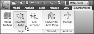
To enter the Studio environment from either a part file or an assembly file, select the Environments tab, and click the Inventor Studio icon, as shown in Figure 16.1.
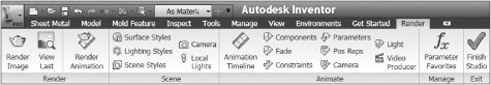
This will set the Render tab active along the top of the graphics area, and it opens the Studio Scene browser in place of the Model browser. The Render tab is divided into four panels organized by task—Render, Scene, Animate, and Manage—each containing tools for those tasks. Figure 16.2 shows the Render tab.
Studio's Scene browser is a custom browser that contains folder nodes specific to Inventor Studio. Right-clicking a folder node allows you to create one or more productions, animations, cameras, and local lights within the same file. The instances are maintained in the corresponding folder.
Three types of styles are used in Studio: surface, lighting, and scene styles. Each has a different purpose and contributes to the final image you produce. In the style dialog boxes, covered in the following sections, you'll see a set of four common tools and, where applicable, a set of tools for the particular style's dialog box.
Figure 16.3 shows the style categories on the Render tab and the common style tools in the each style dialog box.
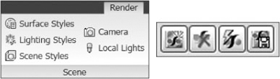
From left to right, the style tools are as follows:
Clicking New Style creates a new local style based on the Inventor defaults. Local styles are available in the current document but are not available globally to all documents.
Clicking Purge Style removes the selected local style from the list.
Clicking Update Style updates the selected style from the style library.
Clicking Save To Style Library saves the selected local style to the style library. The style becomes global, available to all components, when saved to the style library.
Keep in mind that style modifications are applied to the selected style. A style does not have to be active or in use to be modified. We'll cover surface styles first by looking at the Surface Styles dialog box. Then we'll look at the Lighting Styles and Scene Styles dialog boxes.
Surface styles are the means by which you create color and texture for your components. Many surface styles are combined in collections called categories, which are containers for styles. The Surface Styles dialog box has a variety of controls to assign color, reflection, opacity, and diffuse and bump maps, as shown in Figure 16.4.
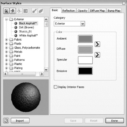
The Surface Styles dialog box consists of the following tabs and sections:
The tool section at the top left of the dialog box is divided into two areas, one for creating and editing the surface style and the other for dealing with the component or face.
The group of four icons along the top left provides tools for creating styles, purging styles, updating styles from the library, and saving styles to the library.
The group of two icons along the top are the Get Surface Style tool, which is used to interrogate faces for their surface styles, and the Assign Surface Style tool (aka the paintbrush), which assigns the current style to a component or face.
The surface style list on the left shows categories, their styles, and the general styles.
The preview pane displays the selected surface style, including diffuse and bump maps.
The rest of the controls are on the other tabs.
To better show how these controls work, we will walk you through the process of taking an existing surface style, creating a new one based on it, altering its appearance, and placing it in a category.
Here are the steps:
Click the Surface Styles icon on the Render tab.
From the general list of colors, select Blue (Sky).
To create a new surface style from an existing style, right-click the existing style, and then select Copy Surface Style. This creates a local copy of the surface style and presents a dialog box so you can name the new style.
Specify a new name by typing Blue Sky (Gloss).
Next, on the Basic tab, assign a category for the new surface style. In the Category drop-down, enter Paint. In this one step, you've created a new category and assigned the surface style to it.
Set the colors accordingly (these values are RGB):
Ambient: 0, 20, 129
Diffuse: 0, 20, 129
Specular: 255, 255, 128
Emissive: 0, 47, 0
On the Reflection tab, set Shininess to 61.
Click Save to retain this local style.
All three style types—surface, lighting, and scene—have corresponding new and copy tools.
On the Basic tab of the Surface Styles dialog box, you specify the category, the color parameters, and the display of interior faces.
As you just experienced, categories either exist or are created at the same time as surface styles. To populate a new category, simply assign a surface style to that named category. In a like manner, by reassigning or deleting all surface styles in a category, you delete the category.
If you create a new surface style that is designed to give a metal appearance, for example, you can set the category for the style to Metals, and the surface style appears in and is accessed through that category folder.
Categories provide a useful means of organizing your surface styles for easy access. To add a new category, simply type the category name, and press the Enter key. The current surface style is assigned to that category, and the category is added to the list in the Surface Styles dialog box.
To remove a surface style from a category, empty it of all surface styles, and it will be removed.
You can use the four color adjustment buttons to set up and control the color properties for a given surface material:
- Ambient
This is the color the component reflects in areas covered by shadow. You can make interesting colors by altering this setting. You can set the ambient color to match the diffuse color using the button between the two inputs.
- Diffuse
This is the color the object reflects in direct daylight or artificial lighting. When referring to an object's color, diffuse color is what is meant.
- Specular
This is the color of the reflections in the object. You can set the specular color to match the diffuse color using the button between the two inputs. Matching the specular color to the diffuse color will reduce the shininess of the object. Specular color changes can provide interesting variations. After you create a diffuse color, experiment with it, adding small amounts of another color using the Specular setting. To clearly see the difference, you should render the scene.
- Emissive
This is the color given off by an object as if it contained a light source that is projecting light through the color. This color does not interact with lighting styles.
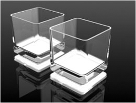
As you define transparent surface styles, determine whether the interior faces will be seen. Consider the simple drinking glasses shown in Figure 16.5; their faces are transparent, so the interior faces are seen. To display interior faces, select the Display Interior Faces option on the Basic tab.
The Reflection tab is where you define the style reflectivity or shininess. For objects that have a matte finish or low reflectivity, you'll use numbers less than 50. The lower the number, the more dispersed the lighting is across the surface. If you are creating a shiny style such as paint, chrome, and so on, then you will use a setting greater than 50.
To give you an idea of where to set the value, Studio's Chrome styles use a Shininess setting of 88.
For any surface style, you can define a reflection map. Inventor surface styles use the default map that is installed with Inventor. However, if you want the surface style to use a specific reflection map, you must specify the map for that style.
To globally change the reflection map, you can replace the delivered image with one of your choice. If you're overwriting the existing map, you must use the same name as the delivered map, Car3.bmp.
Inventor specifies a default reflection map and keeps that map in the Textures directory. For a standard XP install, this is C:Program FilesAutodeskInventor 2010Textures. If you've installed on Windows Vista, the location will differ because of the permission requirements of Windows Vista.
The Opacity tab has two controls, Opacity and Refraction.
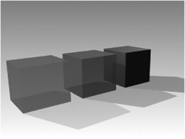
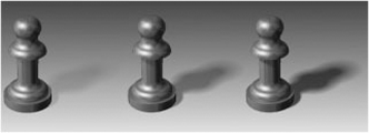
Opacity defines how impenetrable the surface style is for lighting. An easy way to think of it is as the opposite of transparent. The control reflects that notion as well; 100 percent opaque means light will not shine through an object. As you can see in Figure 16.6, the block's opacity setting is increased from one block to the next, starting on the left: 30 percent, 60 percent, and 100 percent. The amount of light that passes through the object decreases, and the shadow darkness increases as less light makes it through the object.
Refraction settings manage the degree to which the light direction is changed when passing through the object. This implies surface style transparency or low opacity. There are preset refractive index values to get you close to where you want to be when using this option. In the dialog box, click the Refraction Presets button above the refraction value to display the list.
The name of common items that have that index of refraction helps you relate to the value and quickly choose one that is closest to what you need. You are able to provide your own value up to an index of 3.0.
A diffuse map gives the appearance of surface texture without bumpiness. You might liken it to a bowling ball that has multiple colors in patterns around it. The surface is smooth but has an interesting surface appearance.
When specifying a diffuse map, the directory where the map resides should be included in the project file libraries or frequently used folders. If not, you will get a warning message.
You are able to scale the image from 1 percent to 1000 percent. If that amount of scaling is insufficient for your map, you will have to do some extra work in an image editor to change the pixels-per-inch/mm ratio. To increase the relative size of the image—for example, if you are working on a building or ship—lower the pixels-per-inch ratio. To map the image to a very small object, you need to increase the pixels-per-inch ratio.
Let's say you have an image that is 120 pixels per inch and you want to cover a large object with that image. Then you would do the following:
Make a copy of the image.
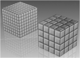
Edit the image by changing the pixels per inch (ppi) to 30 ppi, and create another copy at 12 ppi. The net effect is that the 30 ppi image will be four times as large on the model, as shown in Figure 16.7, and the 12 ppi image will be 10 times larger.
By using this method, you can enlarge diffuse images. At some point, though, the image will not have enough resolution and can begin to look stretched or out of focus. You may have to create or resample an image to use in such a case.
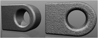
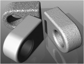
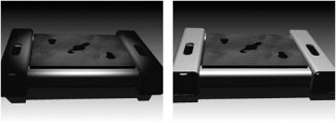
Now that you have a diffuse map, you will want to use a bump map to provide the notion of a textured surface. Inventor Studio has bump maps that match some of the diffuse maps. Figure 16.8 shows the dramatic difference a bump map makes, where the only difference is that the part on the right has a bump map.
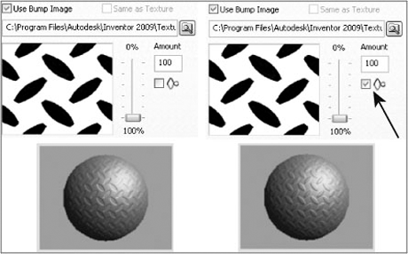
To use a bump map, click the Bump Map tab, and select the Use Bump Image check box. If you want the bump map pattern to match the diffuse map, you can select the Same As Texture option. However, that option may not provide optimal results because displacement is based on the color's lightness (or whiteness, to be more exact). As Figure 16.9 shows, white areas are raised. You can reverse the effect by selecting the Invert option just below the percentage of bump to apply, as shown in Figure 16.9.
The bump map colors do not affect the diffuse map color, but using a colored bump map does affect the degree of bump you can apply. The more black and white you can define on the map, the greater your control over the overall appearance. Therefore, the amount of contrast between the bump map colors plays a part. In Figure 16.10, the middle component is what the component looks like without a bump map. The left component uses a black and white map, which yields the greatest bump contrast. The right component uses a similar but gray and white map. The bump contrast is less visible.
The control beneath the percentage input field inverts the bump effect. This control is very useful when you specify that the bump map is the same as the diffuse map.
As mentioned earlier in the chapter, the Surface Styles dialog box contains the tools Get Surface Style and Assign Surface Style. After selecting the part or face, use Get Surface Style to find out what style is assigned. The dialog box displays the surface style for editing. Use the Assign Surface Style tool to apply the selected style to the selected face or component.
If you are working on applying surface styles to specific faces or features, you must be working in the part document. To assign a style to an assembly, sublevel or top-level, you must be working in the assembly document.
Several lighting styles are provided with Inventor, and you can use them as is or modify them to meet your needs. You can also create new lighting styles to suit your needs. Lighting styles differ from surface and scene styles. Lighting styles have settings that affect all lights in the style, and individual lights have settings for only the selected light. Thus, you will find on some of the light-related tabs the option to have those parameters observe the style settings instead of being individually controlled.
On the Render tab, next to the Surface Styles tool is the Lighting Styles tool. Click to activate it and display the Lighting Styles dialog box. The New Light button (the lightbulb along the top of the dialog box) adds a new light to the selected lighting style. The new light dialog box displays, where you specify the settings.
Next you'll explore the light styles and what they control.
In this section, we'll discuss the lighting style settings. The settings affect all lights in the style. In the Lighting Styles dialog box, a list of lighting styles is presented on the left. Each style has a set of controls:
|
|
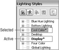
Note that the active style, currently displayed in the scene and used for rendering, is listed with bold letters, and the selected style, the one whose settings are exposed for editing, has background fill, as shown in Figure 16.11. You can double-click a style in the list to edit it. The style does not have to be the active one.
Besides the common style tools, you'll also see a New Light tool in the tools area of the Lighting Styles dialog box. This adds a new light to the lighting style you have selected in the list. The new light then is made the active edit target so you can complete the definition.
Brightness controls the overall style brightness. This tool affects all lights in the style.
Skylight is the tool that provides uniform, directionless illumination in the scene. When enabled, you are able to specify light intensity and color, or you can use an image for lighting the scene. The image supplies colors for the lighting but should not be confused with high dynamic range image (HDRI) illumination.
Using the Skylight and Bounced Light tools is computationally intensive, and therefore they should be used sparingly, usually for final renders only.
The Ambience setting controls the amount of ambient light used in the scene. Setting the value higher increases the amount of light in the scene, so if you have a scene that is lit but is too dark and needs a minor adjustment to get more light, try increasing the Ambience setting.
The Bounced Light setting is a component of global lighting and is included when the Skylight option is selected. However, you can use Bounced Light without the Skylight option. Bounced Light provides the lighting that comes from objects as light encounters them and then reflects off the surfaces. With Bounced Light, you have the option of using preset values for the number of rays that are sampled for bounced lighting. There is also a custom setting should you decide you need a value other than those provided.
The Shadows tab provides access to the following:
- Type
You can specify None, Sharp, and Soft.
- Quality
You can specify Low, Medium, and High.
- Density
You can specify 0 to 100 percent.
- Light Parameter
Here you specify the spherical diameter for a soft shadow effect.
If the light casts no shadow, then the type should be set to None, and all other controls on the page are disabled and not used.
Sharp shadows provide a well-defined shadow, where the boundaries of an object define a sharp contrast between shadow and nonshadow areas.
Soft shadows blur the area between shadow and nonshadow areas. The Light Parameter setting, available only for soft shadows, defines the spherical diameter of influence for soft shadows.
Figure 16.12 shows a comparison of the three shadow types: None, Sharp, and Soft shadows.
Note that the Light Parameter setting controls the penumbra (dispersing shadow around the darkest part of the shadow) and that it is a diameter dimension.
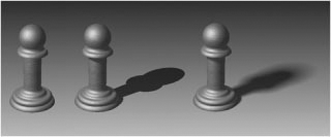
Shadow density provides an additional level of control because you can set the density on a per-light basis. As Figure 16.13 shows, the shadow density increases with the value of the parameter.
It is easy to see how working with these settings you can greatly affect the results of your rendered image or animation.
As mentioned earlier, the Light Parameter setting is a spherical diameter value that controls the influence of soft shadows. If you want soft shadows around the whole scene, then the sphere must be set to be somewhat larger than the scene. If the influence is to be limited, you can use a lower setting. A good rule of thumb is to estimate the extents of your assembly and add 10–15 percent for a reasonable penumbra.
The Position tab gives you access to the orientation, scale, and location of the lighting style.
Orientation is derived from one of the following:
- Canonical origin planes
XY plane, XZ plane, YZ plane.
- Scene style ground planes
Available in the drop-down list.
- Any model face or work plane
Use the select button.
If you want to reverse the lighting style orientation, you can use the Flip button next to the drop-down list and invert the direction of the lighting style.
Scale affects all lights in the style. This allows you to quickly modify your lighting style to fit the model conditions. You can specify any scale factor from 1 percent to 1000 percent.
Lighting style position is expressed in model units and is based on the center of the top-level assembly. If you want to relocate the entire style, the position settings allow you to easily reposition the lighting style.
To add a new light to an existing style, use the New Light tool in the dialog box or context menu in the light style list. Then follow these steps to produce a new light:
Specify a face to act as the light target and normal. The face selection determines the light target location and beam direction.
After selecting a face, you'll see a straight line proceeding from the target or face; drag your mouse pointer along that line to define the light position.
In the dialog box, modify the light parameters to fit your needs.
If you adjust the settings before defining the position, return to the General tab, and select the Target or Position tool to begin specifying the light position interactively.
You can create new lighting styles in three ways:
When you create a new lighting style, you are provided with each of the three types of discrete lights. You can change the light types, add more lights, and modify parameters to achieve the lighting effect you want.
If you copy an existing lighting style, you are able to rename it, modify the parameters, add new lights, or change the light types for the existing lights.
If you have an exported lighting style that you want to import and use, you can use the Import tool, which is the button at the bottom of the dialog box; navigate to the appropriate file, and then import it. Be advised, though, that if you import a lighting style with the same name as an existing lighting style, the imported style will overwrite the current same-named style.
In the lighting styles dialog box you can create and edit individual discrete lights for each light style by using the New Light button. When you create a new light the tabs in the Lighting Style dialog box reflect the settings for that light, rather than the style. Discrete lights can be one of three types: directional, point, or spotlight. Certain controls for the discrete light types differ from the style controls, but shadow parameters can be linked to the style and managed globally for the style from there.
Discrete lights, though three different types, all have but one set of parameters. Based on the light type, access to invalid parameters is blocked. This provides a distinct ease-of-use feature, switching between light types without having to delete and re-create new ones. You can experiment with different light types quickly and determine which is best for your circumstances.
Figure 16.14 demonstrates the difference between a spotlight (left) and a point light (right). The light type is the only difference. The spotlight was set up for the scene, rendered, and then changed to a point light; then no other changes were made, and it was rendered again.
As you can see, the difference can be dramatic. The point light sends light in every direction, whereas the spotlight can be pointed and focused on an area of interest. As you work with lights, experiment so that you learn their characteristics and are able to easily add the type of light you want to a scene.
When you create a new light or select an existing light to edit, you'll see the options on the General tab become specific to that light. On the General tab, you're able to do the following:
You can define the light type; you can choose Directional, Point, or Spot.
You can set the on/off condition. This condition can be animated.
You can redefine the position and, for the Directional and Spot types, the target.
You can flip the light, reversing the target and position locations.
You can copy and paste lights, so once you've set one up, you can quickly duplicate it. You cannot create arrays of lights.
The Illumination tab contains controls for light color and intensity. Intensity is a percentage value from 0 to 100 percent.
Light color, as most people realize, helps inject emotion into a scene. Warm colors (yellows, oranges, reds, and so on) evoke a different response than do cool colors (blues, greens, and so on). Let's say you want light in the scene but would like to give the impression it is turned off at a certain point. However, you want enough light to see the scene clearly. How can you achieve this? Instead of actually turning the light off, you could change the color and intensity of the light from yellow at 80 percent to light blue at 30 percent, giving the impression the light is off while still illuminating the scene.
The Shadow tab duplicates the style Shadows tab. Thus, the shadows of any discrete light can be linked to the style shadows and derived from there. If you choose to have the selected light use different settings, deselect the Use Style Settings check box. Then, specify the settings for the selected light.
Directional lights provide parallel beams of light from a single direction. The light source is considered as being an infinite distance away. Thus, you could use directional light to simulate sunshine. To add to that metaphor, the positional information for a directional light is defined by longitude and latitude values.
The latitude and longitude controls easily relate to seasonal positioning for lighting. You need to be familiar with where the seasonal lighting is for your geography.
Directional lights do not participate in soft shadow lighting. The control is disabled for any directional light.
Point lights cast light in all direction and therefore have only position parameters for locating the light. The light target is ignored and for all intents and purposes is considered as traveling with the light position. Position values are listed in absolute X, Y, Z values based on the top-level assembly origin.
The light decay controls apply to point lights and spotlights only. These controls have an impact on how real the lighting looks. There are three decay types:
- None
This specifies that light energy will not decay over distance. If you want indirect light to remain constant throughout the scene, regardless of the distance between objects, use this setting.
- Inverse
Light energy decays at a rate proportional to the distance traveled. Photon energy is 1/r, where r is the distance from the light source.
- Inverse Squared
Light energy decays at an inverse square rate. Photon energy is the inverse of the square of the distance from the light source, that is, 1/r2.
In the real world, light decays at an inverse square rate. However, for lighting to be realistic, the light values must also be real-world accurate. You'll find that it takes more lights to amply light a scene when you use Inverse Squared for decay.
The rendering cost, in time, increases as you move from no decay to Inverse and again from Inverse to Inverse Squared. For most renders, you can use None or Inverse and get good results based on how you set up your lighting style. When using light decay, you are able to specify the distance from the light source when the decay begins to occur. The greater the decay start distance, the brighter the light will appear to be. This means that if you have a lighting style you prefer but want to make it less bright in some areas, you can change specific lights to use Inverse decay and have a considerable effect on the output. Light decay is a setting that takes experimentation to get a feel for when and how to use it.
Spotlights provide light in a more focused manner, at a specific location. For spotlights, there are more controls for adjusting the light parameters. You can do the following:
You can explicitly position the light target or light source.
You can specify the light hotspot and falloff.
You can specify the light decay type and start distance.
As discussed thus far, you can modify lighting styles giving explicit values for input. You can also interactively modify lighting styles. For example, you can edit position, target, hotspot, and falloff interactively.
To interactively modify any of these settings, you must first edit the light you intend to change. Place your mouse pointer over the light graphic, which is the light node in the Scene browser, and right-click; then select Edit from the context menu. At this point, place your mouse pointer over the graphical representation of the element you want to edit, and do one of the following:
Click the light source to display the 3D Move/Rotate tool for modifying the position or target.
Click and drag the graphic representing the hotspot or falloff to change its size.
Click the line representing the light beam; it connects the position graphic to the target graphic. The 3D Move/Rotate triad is placed over the center of the line, enabling a reposition of the entire light. Click and drag the arrow to move the light in that direction.
Local lights are discrete lights that belong to the scene but not the lighting style. They are useful for control panel lights, and so on, that you may want to animate individually. Thus, local lights come only in the Spot or Point light type. Local lights travel with components, so if you create a lightbulb component, you can specify a local light for use with the bulb object. The advantage is when you animate a component with a local light, the light travels with the component.
Local lights use the same controls as discrete style lights. In fact, you can easily create a local light by right-clicking any style-based discrete light and selecting the tool in the context menu.
Local light settings and position can be animated only when the light is at the top level of the assembly or part model.
Scene styles provide a backdrop for your scene. You can use a single solid color, a gradient color, an image, or a spherical image. What you use depends on how you want to compose your scene.
Scene styles provide a built-in ground plane that eliminates the need for you to add geometry in the model to provide the illusion of ground or a surface on which your assembly is sitting. However, if you have specific needs or use props that replace the ground plane, then it is not necessary to show shadows or reflection. The Scene Styles tool is located in the tool panel next to the Lighting Styles tool.
The Background tab provides access to the various controls for specifying the type of background and location of images to use. You can forego specifying any of this information by selecting the Use Application Options check box. The current Inventor background will be used. You can choose from four background types, covered next.
If you want a single solid color background, click the Solid Color button, and specify the color to use in the Colors section.
You could use the Solid Color option to produce an image so that the background could be removed or specified as a transparent color. However, there is a much easier method that we'll discuss when it comes time to render images; see the "Composing and Rendering Images" section for more information.
Color Gradient is a popular choice because it has the potential to look more like a presentation. Both color controls become enabled, and you specify the top and bottom gradient colors, respectively. With the environment controls, you can further tune the background, using shadows and reflection, to make the scene style complement your model.
Experiment with different solutions. You'll find some really nice sets of colors that work well together. For example, the use of dark blue (top) and black (bottom) with reflections on and set to 80 percent looks very elegant with the proper lighting.
The Image setting enables the image controls at the bottom section of the dialog box. When you activate this choice, the Open dialog box is automatically displayed so you can select the desired image. The default location for the image choices is the Textures directory that is created and populated during the Inventor installation. If you plan to use images other than those supplied, you should do one of two things:
Edit the project file to include the directory where the images are located as a library. (This is recommended.)
Place any image you will use in the installed Textures directory.
Figure 16.15 demonstrates the use of the forest 2.bmp background. The proper placement of the assembly relative to the background enhances the end product. Be sure to take the time to analyze your background to see what may need to be adjusted to optimize your output. In this instance, we arranged a lower camera angle and turned on shadows in the scene style. The lighting style was set to produce soft shadows.
When the image section is enabled, you have three choices of how to use the image in the scene. You can center, tile, or stretch the image. If you choose to tile the image, the Repeat controls are enabled for your use. A little later in the "Matching Your Camera to an Image" section we'll discuss how to match the model view to your image.
The Environment tab manages the ground plane orientation, shadows, reflection, and environment mapping.
The scene style ground plane orientation is based on one of the three canonical assembly work planes. Select the orientation you desire, and specify an offset, if any is required, to position the plane at the proper height for your model. Negative values position the ground plane below the assembly plane to which it is parallel.
The option to show shadows is useful when the scene style is acting like a ground plane for the assembly, in other words, not using any prop models or other model to serve as a floor. The Show Shadows setting specifies whether shadows are cast on the scene style ground plane.
If your scene style is serving the purpose of a model ground plane and you want to reflect the model in the ground plane, select the Show Reflections option, and adjust the percentage of reflection you want in the rendered image. The higher the numbers, the more reflection you see in the ground plane. If set to 100 percent, it will reflect the assembly as if it were sitting on a mirror.
The Use Reflection Image setting is there for you to specify an environment image map. This is the image you will see reflected in those parts having reflectance in their surface style when rendered. Depending on the image, it can have minor to major influence on the rendered outcome. Here again, experimentation is the best teacher.
Collect or produce a set of widely different images, and make new scene styles using the images for reflection mapping. Render the same model with the different styles to see what sort of influence the image produces.
If you want to match your model up to a photograph, use the Image Background type for the scene style. Analyze the photo you will use for the background. Determine where the light is coming from and how much shadow is being cast. Then, set your view to use a perspective camera. Orient the model so that its horizon and vanishing point are similar to the image. Next, create or modify a lighting style so that it produces light and shadows similar to those in the photo. Do a few test renders, and refine the camera position and lights until you're able to get something that looks like what you want.
Here's an example of the workflow you can use:
On the Get Started tab, click the Open button.
Browse for the file named
mi_16a_001.iptlocated in the Chapter 16 directory of the Mastering Inventor 2010 folder, and click Open.Select an image, and make a scene style using the Image background type. You can use the mountain background image named
mi_16a_001.tifin the Chapter 16 directory.Orient the model, as shown in Figure 16.16, to look like it fits into the scene.
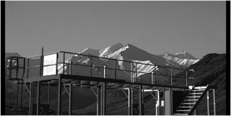
Use the Outdoor lighting style, and scale it to fit the scene. To make sure the shadows are close, modify the style orientation to match the shadow angles on the mountains. Do a test render, make a couple of tweaks to the style position, and then render the image, as shown in Figure 16.17.
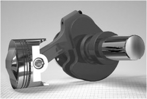
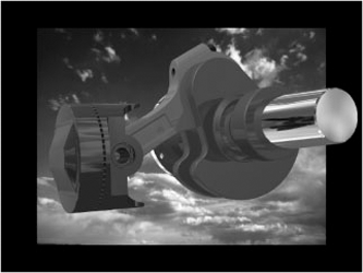
In the next example, Figure 16.18, we used an existing Inventor background, centered in the scene. We used a previous release Inventor sample model—an engine assembly. This time, we wanted to produce an image more for marketing purposes. So, to help make the product (the sample assembly) emerge from the image, we oriented the assembly and made it large enough to extend beyond the background image, giving the illusion of it protruding from the image. We then rendered the image.
Although it is good to know how to use the tools to produce styles, it is also important to know the purpose of the image you are composing and rendering. What is its use? Who is the target audience? The type of image you compose and render will be different based on the answers to those questions. For example, if you are producing imagery for an assembly or repair manual, as used by technicians, you may elect to use an illustration style of output as opposed to a realistic style. The noncritical content may be simplified to a degree. However, if you are presenting a product to a group of investors or potential customers, you may want to compose an image showing the product in its anticipated environment. The use of props can add context to your image or animation and possibly add more realism.
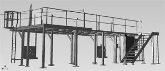
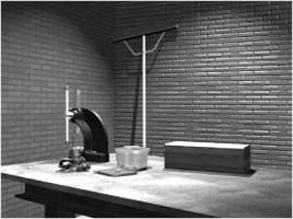
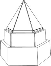
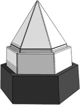
Since you are using an engineering assembly to create an image, it is likely you do not want to alter the engineering models for the sake of the image—not adding prop content to an engineering model. So, the recommended step is to place the product model into a wrapper assembly. Wrapper assemblies are simply a level higher assembly that include the engineering assembly and can contain nonengineering content that serves as props for composing the final rendered images or animations. Let's say you are producing a product that is used in a machine shop. You place the product's final assembly in a wrapper assembly and add shop content, such as walls, tables, tools, and so on, to set the stage for the rendered image or animation, as shown in Figure 16.19.
As you can see, there is nonessential content in the scene, but when combined, those items contribute to communicating a purpose for the items in the image. Even the surface style on the tabletop evokes a sense of a well-used workbench. It is small touches such as these that enhance your images.
Although you might conclude that cameras would be best used for animations, they are also very useful for working with images. Cameras make it easy to recall view orientation, and they can be animated. There are two methods for creating cameras: the Camera tool and the view context menu.
To use the Camera tool, located on the Render tab, do the following:
Click the Camera tool.
Select the target, a component face. The camera direction line is presented normal to the face preview and selection. Click to select the target. The tool then cycles to the camera position input.
Specify the camera position by moving the mouse pointer over the camera direction line and moving it along the line. When the preview is satisfactory, click to select the camera position.
If you select the Link Camera To View check box, the camera graphics are hidden, and the view is changed to what the camera sees. When the check box is deselected, the camera graphics are restored. This gives you an easy way to check your settings.
Set the Camera Zoom value to fit your requirements.
Depth Of Field provides two methods of setting the range of focus: Focus Limits and f-Stop.
The Focus Limits setting provides you with near and far values, in model units. Content between the near and far values will be in focus. Content outside those values will be proportionally out of focus. f-Stop, the other method, uses an f-Stop value and a Focus Plane setting.
To make setting up the camera a little easier, you can link the focus plane to the camera target. Then, whenever the target is moved, the depth of field adjusts to fit with the camera. That makes less work when it comes to updates.
Click OK, and the camera is created. You can rename the camera with the browser node slow-click method.
The graphic region context menu method is useful for rapidly creating a camera using the current view. To access the other camera settings, you must edit the camera after creating it. To use the graphic region context menu method, simply orient the view so it displays what you want the camera to show, right-click, and click Create Camera From View. A camera is added for this position. You can edit the other camera parameters via the Camera dialog box.
It is not unusual to have 8 to 10 cameras defined when you consider the various vantage points from which you might look at a product.
Now that the stage is set, the lighting selected, and the model positioned, you're probably anxious to render something to see how it's coming. You can always render using the current view. So, whatever position you set the view to, you can render and get results. It is not required that you have a camera defined in order to render. However, repeatably getting back to that same camera location, settings, and so on, really requires that you define a camera. So, before discussing rendering, we'll talk briefly about setting up a camera.
The easiest method, by far, is to orient your model, choose orthographic or perspective viewing, and then in the graphic region right-click and select Create Camera From View. That's it! You have defined a camera. Now, you can easily recall that camera if you change the view orientation. As with any Inventor browser, you can click the node twice and rename it. We recommend naming your cameras for ease in selecting, recalling, or animating them.
The Render Image tool presents the Render Image dialog box with three tabs: General, Output, and Style. The following sections will briefly discuss the controls and use of the Render Image tool.
The General tab contains controls for sizing the image and for specifying the camera, lighting style, scene style, and render type to use in producing the image. Active styles prepopulate the style choice fields.
The size controls, Width and Height, provide you with explicit image size control. Directly to the right is a drop-down list of predefined image sizes that are typical in the industry. Beneath the drop-down list is a check box for locking the image aspect ratio. If you determine that a specific image size is consistently used, you can enter the values, lock the aspect ratio, and then create images at that ratio or at any size within the permitted limits. This makes scaling an image, post-rendering, easy.
As mentioned earlier, the camera choices include those you have defined and Current View. If you are doing test renders at a low resolution by moving the camera around to see where the best shot will be taken from, use Current View. It's simple and straightforward. Once you determine the camera locations, you can then define and refine those positions and camera settings.
The Lighting Style drop-down list shows all the available lighting styles, local (document) styles, and global styles (the style library), including those you have made and maintained locally or in the style library. If you have activated a lighting style, it is preselected. Specify the desired lighting style.
As with the lighting style, the same is true of the scene style. Make your selection based on available local and global styles.
As you were composing the scene, likely you determined whether the end result would be rendered as a realistic or illustration image. Here is where you set that choice. The choice dictates what controls are available on the Style tab.
The Output tab contains controls for where the image is saved and whether to use antialiasing and to what extent to use it.
If you want to save the image, select the Save Rendered Image box. When you do so, the Save dialog box displays. You specify the location and name for the image. If you don't specify this in advance, you are still able to save the image from the render window.
The antialiasing tools include the following choices, from left to right:
- None
Antialiasing is not used. This selection requires the least render time and provides the coarsest results.
- Low
This specifies a low antialias setting. This eliminates the major coarseness seen in the None selection but still displays a degree of coarseness.
- High
This specifies a high antialias setting. This setting virtually eliminates all signs of coarseness in the image. For final renders, in scenes without soft shadows, this selection performs very well.
- Highest
This specifies the highest antialiasing setting. This setting is provided particularly for use with refining the image's soft shadows.
With each selection there is an increase in quality accompanied by an increase in render time. Thus, when you select the Highest setting, recommended for soft shadow use only, the quality is increased, as is rendering time. It is up to you to determine what meets your need.
When using the Realistic style, there is only one control on the Style tab, True Reflections. When selected, this option ensures that the objects in the scene are seen in reflective surfaces. If not selected, the image map specified in the surface style or scene style is used.
When using the Illustration style, several settings yield a variety of results. We'll cover some of these next.
To render a line art illustration like you might see in a technical or assembly manual, do the following:
Set the graphics display to use the Presentation color scheme with the background set to 1 Color. Color scheme selection can be set by going to the Tools tab, clicking Applications Options, and going to the Colors tab in the dialog box that opens.
In Studio, set up the model conditions to fit your requirements. If you want to show something in the state of moving, then use an animation, and select a time position that illustrates the condition.
Activate the Render Image tool, and specify the Render Type setting as Illustration.
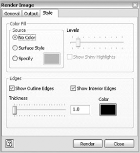
On the Style tab, set Color Fill Source to No Color, as shown in Figure 16.20. Since there is no color, you likely want the exterior and interior edges to show. Select both options in the Edges section.
Render the scene. The results will be something like Figure 16.21.
Take some time to experiment with these settings, and you will be able to come up with some very interesting imagery. For example, make the following changes to the Illustration rendering type settings:
On the Style tab, set Color Fill Source to Surface Style.
Set Levels to 5 (midway across the slider).
On the General tab, set the lighting style to Table Top.
Render the scene. The results will look something like Figure 16.22.
As you can see, with just a few changes, you can get dramatic differences. Using the same settings, render the scene with a different scene style. The results really start to get interesting.
Inventor Studio was designed to use assembly constraints to produce the mechanistic movement within your assemblies. You should consider the following basic concepts when it comes to animating with Inventor Studio:
When you enter the Inventor Studio environment, the model is considered to be in model state, that is, whatever the condition the model was in when you left the part or assembly environment. This means when you exit Inventor Studio, modify the assembly, and then reenter Inventor Studio, the assembly changes are reflected in the model state. That includes view representations, positional representations, component visibility, position, color, and so on. For animations, the model state represents frame 0. Therefore, all modifications affecting the model state also affect all animations in that document because frame 0 has changed.
Modifications made in frame 0 of the animation become the starting point for that animation. For example, component 1 in animation 1 is flush with component 2. In animation 2, the flush constraint for component 1 is offset by 1.5 inches. By changing the constraint in frame 0 for animation 2, you don't cause a change in animation 1. Had you changed the flush offset in the assembly or Studio model state, animation 1 would also be affected.
Because Inventor Studio animates constraints, the free-form movement of a component, part, or assembly may require suppressing constraints that limit movement or the component's degrees of freedom.
Animation actions are a result of modifying constraints; thus, any component that is constrained to a moving object will also move.
The Animation Favorites folder contains all the constraints that have been animated in the active animation. It also contains any parameters you have nominated to appear there. This makes it easier to locate any parameters intended for animation and those constraints that have been animated.
Animation dialog boxes have a common workflow through the dialog box—specify the animation parameters, and specify the time parameters. Based on the animation action target (component, light, camera), the dialog box presents controls relative to the target.
Editing an animation action uses the same dialog box and therefore has virtually the same workflow.
All animation tools are applicable to assemblies. However, in part models only cameras, lights, and parameters can be animated. The Render tab is divided into panels. Animation tools are grouped on the Animation panel.
You can find the Animation Timeline tool on the Animation panel of the Render tab. The animation timeline is where animation actions for any object are maintained and managed. Any time you use an animate tool, it results in an animation action that is placed in the timeline. Animation actions can be interactively changed using the start or end handle, as well as action's location along the timeline by using the middle section of the action graphic or by editing the animation action.
To edit an animation action, use the action's context menu, or double-click the action graphic in the timeline.
The playback tools are along the top left of the window. These are similar to other timeline or video playback controls you have used. Figure 16.23 shows these and the other timeline controls.
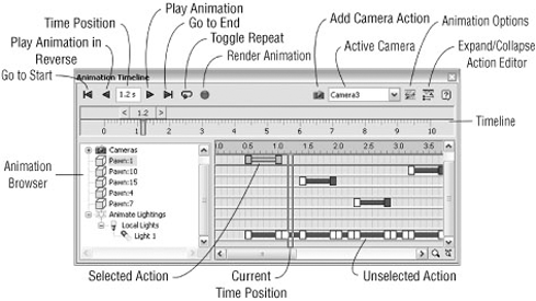
The tools provided are as follows:
- Go To Start
Moves the timeline slider to frame 0 and updates the graphics region to show frame 0.
- Play Animation In Reverse
Is just as the name implies. You move slider to a point in time, you click the tool, and the animation plays in reverse.
- Current Time Mark
Specifies the current time position. You may type into the field to explicitly change to another time position. The graphics region updates content to show what the animation looks like at that time.
- Play Animation
Does what the name implies; plays the animation forward from its current position.
- Go To End
Puts the time slider at the end of the animation. The graphics region updates content to show what the animation looks like at that time.
- Toggle Repeat
Turns on the repeat tool. When you play the animation, it will automatically repeat until you click Stop.
- Record Animation
Activates the Render Animation tool and displays the dialog box.
You can edit selected actions with the dialog box by double-clicking the action in the track section, where the action bars appear, or by right-clicking the context menu and selecting Edit.
You can edit action duration without going to the dialog box; just hover the mouse pointer over the start or end handle, and then click and drag the handle to change the position. Hovering over the center of the action and then clicking and dragging moves the entire action in the timeline.
Animation Favorites is a list that contains any animated constraint or parameter that you have nominated for animation. The purpose is to make it easy to find those animation targets when you need to see or use them.
To populate the folder with a parameter, the parameter must be nominated by you. To do this, activate the Parameters Favorites tool. The Parameters Favorites dialog box, shown in Figure 16.24, displays, and you select the box in the row of any parameters that you plan to animate.
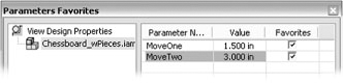
This causes the parameter to populate the Favorites list. From there you can use the Animate Parameters tool however you'd like.
In each animation tool dialog box is a section entitled Time.
The Time section contains all the controls to manage an animation action's time allocation. You specify whether the action starts from the end of a previous action, is a specified time range, or is instantaneous.
Based on the time method, you are able to specify a start time and duration, duration and end time, start time and end time, or simply an end (instantaneous only). The default method is From Previous, which starts the action at frame 0 if there is no previous action defined; otherwise, the new action begins at the end of the previous action.
The other common tools are those on the Acceleration tab.
The Velocity Profile setting defines how rapidly an action starts, proceeds, and ends. You can specify an action to occur at a constant speed. The default option specifies that the action starts with zero velocity and then takes 20 percent of the action duration to achieve complete acceleration. The next 60 percent of the duration is at full acceleration. The last 20 percent of the duration decelerates until it reaches zero at the end of the action. The longer the action, the more observable this becomes.
Think in terms of an electric motor; when it powers up, acceleration is not immediate but occurs over a period of time, however long or short. When the power is turned off, the armature decelerates and eventually comes to a halt. This is essentially what occurs with the animation action based on the Velocity Profile setting.
The values presented in the dialog boxes are in the document's units.
You can access the appropriate animation tool from the context menu of the item that is to be animated. For example, you can right-click a constraint and select Animate Constraints to animate the selected constraint. The same is true of the other animation tools and their corresponding browser nodes.
As we discuss the individual animation tools, we won't include the common sections.
You can find the Animate Component tool on the Render tab. Animate Component is used for the unconstrained animation of parts or assemblies. Think of it as animating a component's degree of freedom. Note that if a component does not move when you create an animation action for it using Animate Component, it likely has a conflicting constraint.
The Animate Component controls are as follows:
- Select Components
This is active (default) when initiated; select the component, part, or assembly that will be animated.
- Position
This displays the 3D Move/Rotate triad to allow you to implicitly move or rotate the component as desired. Selecting the arrowhead indicates a move vector. Selecting an axis, between the arrowhead and intersection, indicates a rotation axis.
- Distance
This is where you enter the distance value. Specify this value after selecting the vector on the Position triad.
- Rotation
This is explicit input in degrees for a rotation action. Select the axis to be used for rotation.
- Revolution
This is explicit input for the number of revolutions the animated component will make. This is an alternate way to input rotation.
- Path
This has two options, Sharp and Smooth. Sharp uses no smoothing between the start, duration, and end values. Smooth uses a continuous motion curve between the start, duration, and end values.
You can find the Animate Fade tool on the Render tab. The Animate Fade setting changes the opacity of a component over time. The parameters allow for this to happen over any defined period of time or instantly if you desire. You can animate to any level of opacity, from 100 to 0 percent.
This tool is useful for fading components to reveal interior components while still giving a sense of the overall envelope, as shown in Figure 16.25.
Animate Fade is not associated with a component's visibility state; rather, it is a separate control for animating component opacity. This means you must create an instantaneous action in frame 0 for the component to start out with less than 100 percent opacity.
For example, if you were to start an animation of a transmission with the housing at 10 percent opaque, you must create the action at frame 0 for the opaque value. Then, during the animation, you could create a different action to increase the Opacity value in order to make the housing 100 percent opaque.
The Animate Fade controls are as follows:
- Select Components
Active (default) to allow selection of the objects to fade
- Start
The component's percent Opacity value at the start of the action
- End
The component's percent Opacity value at the end of the action
You can find the Animate Constraints tool on the Render tab. Assemblies are built using constraints that remove degrees of freedom and cause components to remain in place with relation to one another. They also work as engines to cause mechanistic movement. Thus, constraints make it easy to animate objects.
The Animate Constraints tool is used to modify a constraint over time. The component's orientation changes as constraints are modified.
The constraint's current value is the starting value, and the value you give the end parameter determines the degree to which the object, and those constrained to it, responds.
When animating with constraints, there will be times when something does or does not respond. This is most often caused by other constraints causing a conflict with the animated constraint. One way to overcome this condition is to suppress the conflicting constraint if that doesn't cause a radical change in the animation or its purpose.
You can find the Animate Parameters tool on the Render tab. If you have used parameters in your assembly and want to animate the parameters, this is the tool you will use. The parameter must first be added to the Animation Favorites folder, as discussed earlier.
You can also use Animate Parameters with part parameters. As a result, you can morph the physical shape of a part given the right set of parameters and animation actions. For example, let's say you are designing a vascular stent. As part of the product presentation, you want to show the degree to which the stent can expand and perform its function. How would you do this?
If you've created user parameters on a part or assembly, you can access the parameters and animate them with these basic steps.
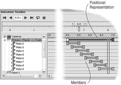
You can find the Animate Positional Representations tool on the Render tab. Positional representations (aka PosReps) use constraints to locate components while respecting the other constraints. You could conclude they work almost like keyframes for a Studio animation. And, in fact, Inventor Studio treats them almost like that. Studio allows you to animate between positional representations.
All that is required is specifying the two PosReps and time over which the transition is made. Studio does the rest. To animate a positional representation that is "deep," meaning it is deeper within the assembly hierarchy, you will need to set the subassemblies, between the top level and the component owning the positional representation, to Flexible. You do this using the component's context menu. The top-level PosRep must cause the "deep" PosRep to be activated.
You can also activate a "deep" PosRep by creating PosReps in each of the subsequent subassemblies. Each higher-level assembly has a PosRep that calls the child subassemblies' PosRep. This is repeated for each subsequent subassembly.
Editing a PosRep animation action is like any other action, but there is a bonus. If you select the PosRep and expand the node in the Animation browser, you will see the participating members of the PosRep. Each of the members has an action bar, and you can edit the duration and position of the members interactively. The values must stay within the bounds of the defined PosRep. Initially, all members occupy the full span of the action, but you can change that by editing the PosRep. When you edit the PosRep, the members enable so you can adjust them. For an example of what this looks like, see Figure 16.26.
You can find the Animate Camera tool on the Render tab. When animating a camera, the current camera parameters are used as the "from" parameters of the animation action. Using the Animate Camera controls, you define the "to" parameters for the animation action. With these controls, you can do the following:
In the Animate Camera dialog box, you select the camera to animate from the drop-down list. Then, using one of two methods, you define the end position of the camera for that animation action.
The first method is to use the Definition tool. To access the dialog box, just click the Definition button in the Camera section. The steps are the similar to when you define a camera using the dialog box, such as setting the target and position selection, as well as additional animation options.
When you click the Definition button, the Camera dialog box displays, and you are able to specify the following:
Target Placement sets the line of sight the camera uses.
Fixed: The target does not change positions.
Floating: The target maintains positional relationship to camera.
Path: The target follows a path made of 2D or 3D sketch geometry.
Camera Position sets the camera position relative to the target.
Fixed: The camera does not change positions.
Floating: The camera maintains positional relationship to target.
Path: The camera follows a path made of 2D or 3D sketch geometry.
Roll Angle defines rotation around the camera to the target axis, displayed as a line between the camera components.
Zoom defines a horizontal field of view.
The second method for defining camera animation is to use the current view. The steps to do this are as follows:
In the Timeline Active Camera list, select the camera you want to animate.
Position the timeline slider at the time position representing the end of the action you are defining.
In the Scene browser, right-click the camera you specified in the list, and click Animate Camera in the context menu. Alternatively, you can select the camera in the graphics region.
Use the view tools to orient the graphics region to the view you want to see at that time position.
Click the Add Camera Action (camera button) next to the Timeline Active Camera list. You will see the view briefly revert to the last known position and then update to the current position.
Repeat steps 2, 4, and 5 as much as is needed for as many cameras as you want.
If you simply want a camera to travel around your part or assembly in a circle, the turntable function makes this very easy.
To use the Turntable functionality, do the following:
Right-click the camera you want to use as a turntable camera, and click Animate Camera. Alternatively, use the view tools to set the camera to its initial position, right-click, and click Create Camera From View.
Select the Turntable check box to enable the turntable controls. A graphic preview of the current axis is displayed in the graphics region. In the Axis list, select from any of the canonical axes or the current camera horizontal (Camera-H) or vertical (Camera-V) handles.
Specify the direction of rotation around the selected axis.
Specify the number of revolutions.
Qualify the number of revolutions by selecting the literal (+/−), per minute, or per second option. For partial turntable effects, use a value less than 1.
In the Time section, select whether to loop the camera, or use a time period to define the length of the action.
As mentioned earlier, when you select the camera definition method, you have the option to specify that the target or camera follows a path.
If you are planning on animating a camera along a path, you must define the path geometry in advance. You do this in a separate part file using 2D or 3D sketch objects. The part file is added to the assembly and positioned where you want it before ever entering Studio. You can, of course, add the path file later and then animate the camera, associating it to the path.
Note that in order for the path part file to be hidden from the bill of materials, the part should be designated as a reference part.
When you select the Path option, move your mouse pointer into the graphic region, and select the path you want to use. The tool searches for sketch geometry, so there are no conflicting inputs when you are in the graphics region.
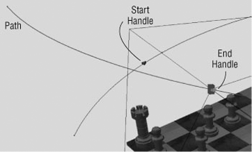
After you select the path geometry, two handle glyphs appear on the path (Figure 16.27): a green triangle at the beginning of the path and a red square at the end of the path. The glyphs perform two functions:
They tell you the direction the camera is traveling along the path.
Also, the glyph can be moved along the path serving as a limit setting for how much of the path is used. To adjust the glyph position, place the mouse pointer over the glyph, and click and drag along the path. Release the mouse button to accept the location.
You can find the Animate Light tool on the Render tab. You can approach animating lights in a few ways. You can animate the lighting style, lights within a style, or local lights. When animating lights, the Animate Light dialog box has the same controls that were used to create or edit the lights. When defining an animation action for a light, you specify the light parameters as they will be at the end of the action. Studio tools use the previous parameter values as the starting point of the animation action and the new parameter values as the ending point of the animation action. You specify the time period over which the action occurs.
The first steps for animating a light are the same regardless of the object to be animated:
Activate the Animate Light tool. Alternatively, select the object to be animated, and use the context menu entry, Animate Light. The Animate Light dialog box displays.
If nothing was selected to start, specify the lighting style, style light, or local light to be animated. The Select tool is active by default.
Click the Definition button.
The corresponding dialog box displays, and only parameters capable of being animated are enabled.
If a style is selected for Lighting Style, you are able to animate the style brightness and ambience parameters.
For a local light or a light in a style, a variety of parameters are enabled for animating. Specify the values you want represented in the animation at the selected time position.
Click OK to commit to the values for the animation. An action is added to the timeline.
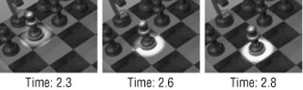
Local lights, when defined in components deeper in the assembly, are not accessible at the top-level assembly for animation. Local lights are meant to be light sources that travel with components. Thus, if you define a local light to be in a part used in the top-level assembly, that light will be lit and be a source of light in any renders or animations. The local light is part of the component, and wherever the component goes, the light goes also. Examples where local lights might be used are lighted gauges, switches, headlights, and so on.
Figure 16.28 shows a sequence of frames at time positions 2.3, 2.6, and 2.8. The local light has both intensity and position animated.
Lights within lighting styles can provide animated scene lighting. Examples of uses are gallery lights, showroom lighting, and so on. Exploring the various ways to animate lights is worth the effort, not only for gaining experience but also for getting an idea of how much light affects everything in the scene.
If you use Dynamic Simulation, part of Inventor Professional and Inventor Simulation, you will see the Create Studio Animation tool in that environment's tool panel, which allows you to render your simulation in Inventor Studio. The tool is used after you have run a simulation but before you leave run mode. You must run the simulation before using the tool.
The tool initiates the studio environment, creates a new animation called Dynamic_Simulation, and adds a new parameter called Simulation_timeline. The parameter is placed in the Animation Favorites folder and is ready to animate. The parameter represents the time steps used in the simulation. For this reason, it is recommended that you use the same number for the parameter value that is used for the images in the simulation. This way, you will be able to relate the animation to the simulation.
Animate the parameter, using the Animate Parameters tool, to see your simulation. Then use the other Studio tools, such as lighting and scene styles, to help enhance the animated result. When you're ready, render the animation.
Video Producer provides the ability to compose a single animation from one or more animations. You are able to select from all cameras that you have set up, whether animated or not. Reasonably, to provide content for a production, you must create one or more cameras and usually at least one animation.
Video Producer supports the following:
It is also possible to create a production of still shots using a variety of cameras.
Video Producer is presented in a window similar to the Animation Timeline window, but with different controls.
The playback controls are the same as those in the Animation Timeline window and most other playback or player software.
The composing timeline and tabbed browser on the left are where you will find the shots and transitions. Shots are the cameras that have been defined in Studio, whether animated or not. Transitions are available to use between shots. Transitions are overlays over the shots, not segments between shots. Therefore, transitions extend into the shot in one or two directions. This means that when you plan to use transitions, you will need to specify enough shot time to allow for the transitions.
When you activate Video Producer, all cameras are collected, and all image representations are made and listed in the Shot browser. This action is session-based. Thereafter, only the cameras that change will be updated when you return to Video Producer during that Inventor session.
Four transition types are available, but five possibilities exist when you consider "no transition" as an option. The transitions are as follows:
You can compose with Video Producer in two ways: via a dialog box or by dragging and dropping. Each has its own advantage. First we'll discuss dragging and dropping, or the interactive means of creating and editing. This method's advantage is fast production layout. Note that the composition is an additive process, starting from the beginning of the production.
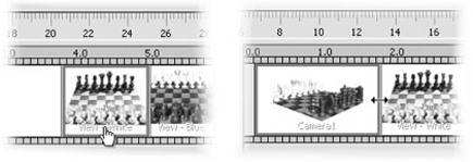
Using the interactive method, you simply determine the camera shot you want to use and then drag and drop it onto the production track. You change the length of the shot by positioning the mouse pointer over either end, horizontally, and then clicking and dragging. Figure 16.29 shows an example of each of these techniques.
You can also drag and drop to reorder the shots in the timeline. For more precise control over the time used and shot segment, double-click the shot, and edit the parameters. Alternatively, use the Edit tool in the context menu.
Transitions behave in a similar manner. You simply drag and drop one onto the track and then adjust them as needed. Double-clicking or using the context menu to select Edit will give you explicit control over parameter values through dialog boxes.
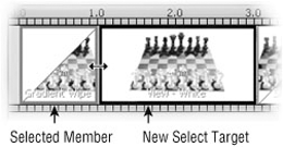
To make it easier to edit contiguous production timeline members, you can select one and then move your mouse pointer over the neighboring member that is to be edited. The selected member displays a cyan highlight, and the new select target gets a red highlight, as shown in Figure 16.30. When both are highlighted, click and drag the boundary between them; they edit and update simultaneously.
In the Shot dialog box there are two sections: Animation Footage and Shot Footage. Animation Footage refers to what the camera records in the animation. Shot Footage is the portion of animation footage that is used in the active production.
In the production timeline, the shot footage displayed is the amount of time in the production that footage is displayed. Any portion of the selected camera, from the designated animation footage, can be displayed during that shot duration.
In the Transition dialog box, you can edit the type of transition and its parameters.
Transitions that start or finish a production use color as the secondary member for the transition. Use the color selection to change the selection.
After placing a shot or transition into the Video Producer timeline, right-click and select Edit to display the Shot or Transition dialog box. In the Shot dialog box, you can edit the following:
In the Transition dialog box, you can edit the following:
You can specify the transition type.
You can specify the transition color.
You can specify the start, duration, and end timeline positions.
These are the same parameters that are being edited when you do so interactively.
It is important to note that if a production is active when you use the Render Animation tool, the active production, and not the animation, will render. If you want to render a single animation and you have productions, be sure to deactivate the production before rendering.
The available animation formats are WMV and AVI, which will be discussed in more detail in a moment.
The Render Animation dialog box is used whether rendering an animation or production. With productions, you have already selected the camera(s), so that field is disabled. If you are rendering an animation, the camera input is enabled.
The General and Style tabs of the Render Animation dialog box use the same controls as the Render Image dialog box.
The Output tab, shown in Figure 16.31, has controls that specify the various parameters for the rendering the animation.
On the Output tab you specify the name for the file(s) that is created. If you use a video format, you can choose from Windows Media Video (WMV) or Audio Video Interleave (AVI). Based on the file type selection and after the OK button has been clicked, you are asked to specify the final parameters before rendering:
- WMV Format
You are asked to specify Advanced Systems Format (ASF) Export properties, in particular, the network bandwidth. If you use one of the default choices and the output is not to your liking, use the custom setting; start with 700, Kbps and increase from there.
- AVI Format
You are asked to specify the video codec of choice. One or more codecs may have been delivered with the computer software. However, these at times may not produce the desired results.
Over the past few years, two video codecs have emerged as ones that routinely give good-quality results with small to medium AVI file sizes. Although this is not an endorsement, it is good to know that the TechSmith (www.techsmith.com) and DivX (www.divx.com) codecs provide very good results.
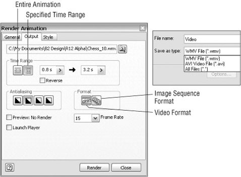
In the Time Range section, specify whether the entire animation or a time range will be rendered. If time range is selected, the timeline fields enable so you can specify the start and end times. If you want to reverse the rendered animation, select the Reverse check box.
Note that the controls on the right side of the input fields give access to the most recent values specified for the tool.
The Antialias settings are the same as those used in the Render Image dialog box; from left to right they are None, Low, High, and Highest.
The Format section is where you specify whether the animation is output in video format or as a list of frame sequences. If frame sequence is specified, the name provided has incremented numbers appended as images are created. If you plan on adding comments within the video or if you do not have enough disk space, you can output as images and then composite them later. This allows you to move the images to another location and continue rendering.
Then, specify the number of frames per second the video will output with. You will find that 24 and 30 frames per second (fps) are commonly used in broadcast and film media. A 15 fps animation may look good to you. Try it at 24 or 30 fps; you will notice the improvement.
A major concern of anyone rendering is the amount of time it takes to generate an image or animation. Rendering an animation without some idea of what it will look like is a potentially expensive proposition at best. To enable better decision-making processes, you are able to create a preview render; just select the box. Preview renders do not use lighting styles and render quickly. This gives you a means of determining whether any adjustments are needed before committing to rendering over a lengthy period of time.
These are the tools and concepts to accomplish rendering and animation in Inventor Studio. The creative part is up to you. Spend time experimenting, and you'll find you can create compelling imagery.
- Create and manage surface, lighting, and scene styles
Creating your own more realistic styles is often the difference between a rendering that looks kind of real and one that is photorealistic.
- Master It
You need to create a surface style that portrays black, bumped plastic.
- Create and animate cameras
Although static camera animations are a common part of any animation, creating and animating cameras give your renderings a much more professional feel. You need to create a camera and animate it.
- Master It
You decide to use the most expedient means to capture camera keyframe positions.
- Start new animations, modify animations, and use the various animation tools
Animating your assemblies so that the function of the mechanism is showcased is often the purpose of an assembly animation.
- Master It
You have an existing animation but want to do a variation on it. You want to copy and edit an existing animation.
- Use multiple cameras to create a video production of your animation
Video Producer provides the means to combine camera shots into a single video output.
- Master It
You have created several cameras, animated and static, and want to make a composite animation.
- Use props to enhance your scene
Inventor assemblies can be combined with other components to create a more realistic scene for rendering.
- Master It
You have completed a design and want to render a realistic image of it in its working environment.
- Render realistic and illustrative images
Inventor provides the means to render both realistic and illustrative images.
- Master It
With your new product nearing completion, the marketing department has asked for rendered images for marketing collateral and technical documents such as white papers.
- Render animations and video productions
Inventor provides the means to render animations and video productions.
- Master It
You've created a wrapper assembly and set up the scene with cameras, lighting, and a scene style. Now you want to render an animation for design review and a video production for a multidiscipline review or marketing use.