
14
Embedded Devices and RFID Hacking
The embedded systems market has been given a real boost by the adoption of the Internet of Things (IoT) by consumers. Modern connected embedded devices are becoming more attractive and are widely deployed across many big corporations, Small Offices/Home Offices (SOHOs), and Small and Medium-sized Businesses (SMB) and are being directly utilized by global household consumers. As per www.statista.com, connected IoT devices have grown from 15.41 billion devices in 2015 to 35.82 billion devices in 2021, and there are expected to be 75.44 billion devices by 2025. In the same way, threats have grown, and the security of these devices has become the biggest area of concern to manufacturers and consumers. A recent good example of this is the vulnerabilities found in Realtek chipsets (CVE-2021-35395) that affected 65+ vendors that produce smart devices. The way the attacks originated indicates that they might have been done by the same attackers that created the Mirai botnet attack that left most of the US east coast without internet in 2016.
In this chapter, we will cover the basics of embedded systems and the role of peripherals and explore the different tools and techniques that can be employed to perform a traditional hardware/firmware penetration test or product evaluation of a given device using Kali Linux. We will also set up ChameleonMini to emulate an NFC card and replay the stored memory contents to bypass any physical access control during a red teaming exercise or physical penetration testing.
In this chapter, you will learn about the following:
- Embedded systems and hardware architecture
- UART serial buses
- USB JTAG
- Unpacking firmware and common bootloaders
- RFID hacking using ChameleonMini
Embedded systems and hardware architecture
An embedded system is a combination of hardware and software that is designed to perform a specific task. The embedded hardware is usually based on a microcontroller and microprocessors. In this section, we will take a quick look at the different architectural elements of an embedded system, including memory and communication between these devices. Pretty much everything that we use on a day-to-day basis is an embedded device, including mobile phones, DVD players, GPS systems, and intelligent voice assistants such as Alexa and other hardware-based solutions.
Embedded system basic architecture
The basic architecture of an embedded system typically includes a hardware and software component. Figure 14.1 depicts the typical architecture components of a simple embedded device:

Figure 14.1: Basic embedded system architecture
The components of an embedded system are as follows:
- Software: This is the custom application to control the device and its features; mostly a web application to configure or update the device.
- Microprocessor or microcontroller: Typical embedded devices are based around the microprocessor and microcontroller. The only difference between a microcontroller and a microprocessor is that microprocessors do not have RAM/ROM, which needs to be added externally. Most of the embedded devices/systems today utilize microcontrollers that have a CPU and a fixed amount of RAM/ROM.
- Hardware: This includes a peripheral device with chipsets, processors such as ARM (most widely deployed), MIPS, Ambarella, Axis CRIS, Atmel AVR, Intel 8051, or Motorola power microcontrollers.
- Embedded operating system: Most embedded systems are Linux-based, and they are real-time operating systems (RTOSes) customized for the device. There might be some questions raised in the tester’s mind, such as what is the difference between the operating system and the firmware? The firmware allows device manufacturers to use general-purpose programmable chips instead of custom-purpose hardware.
Understanding firmware
In electronic systems and computing, firmware is software that can connect to specific hardware that provides low-level control. Every device comes with its own firmware from the product’s manufacturer.
The following list of categories and types of devices are those that typically come with custom firmware, and they are mostly Linux. The following list is not exhaustive in any way:

Figure 14.2: Different types of devices
The following table lists the types of memory utilized in most embedded devices:
|
Type of memory |
Description |
|
DRAM (Dynamic Random-Access Memory) |
This is volatile memory that can be accessed in both read and write mode. It is fast and will need access to the memory contents. DRAM is the reason to employ caching mechanisms in some architectures. The DRAM memory access is timed at the very early stages of the bootloader. |
|
SRAM (Static Random-Access Memory) |
This is volatile memory similar to DRAM that can be accessed in read and write mode. It is faster than DRAM. Mostly, small levels of SRAM that are less than 1 MB will be included on the device (due to commercial reasons). |
|
ROM (Read-Only Memory) |
This is non-volatile memory that can only be read. A mask bootloader is one example of a ROM in embedded devices. |
|
Memory-Mapped NOR Flash |
This is non-volatile memory that can be accessed in read/write mode. This is used during boot code. |
|
NAND Flash |
This is a type of non-volatile storage technology that does not require power to retain data. |
|
SD (Secure Digital) Card |
This is a non-volatile memory card format used in portable devices. |
Table 14.1: Different types of memory
Different types of firmware
Pretty much all embedded devices are powered by different firmware depending on their complexities. Embedded systems that perform heavy tasks definitely need a full operating system such as Linux or Windows NT. The following is a non-exhaustive list of operating systems that are normally found during firmware analysis:
- Ambarella: An embedded operating system mostly used in video cameras, drones, and so on.
- Cisco IOS: Cisco’s Internetwork operating system.
- DOS: A disk operating system that is considered obsolete. But testers never know what they will find during an assessment.
- eCos (Embedded Configurable Operating System): This is an open-source real-time operating system from the eCos community.
- Junos OS or JunOS: This is Juniper Networks’ custom operating system based on FreeBSD for its router devices.
- L4 microkernel family: These are second-generation microkernels that look like Unix-like operating systems.
- VxWorks/Wind River: A popular proprietary real-time operating system.
- Windows CE/NT: The operating system for Microsoft-enabled embedded compact devices; very rare to find on a device.
It is important to understand the difference between the firmware and the operating system. Table 14.2 provides the basic differences:
|
Firmware |
Operating System |
|
It is always fixed data/code that is embedded in any peripheral device or electronic appliance. |
It is system software that is designed to provide an environment to facilitate multiple programs; it acts as a foundational layer. |
|
It resides in non-volatile memory (ROM), for example, BIOS, keyboards, refrigerators, and washing machines. |
It resides on disk, for example, Microsoft Windows, Google Android, and Apple iOS/macOS. |
|
It is a low-level operation and is mostly used for a single purpose. |
It is a high-level interface and a multi-purpose system that allows different kinds of software to run on multiple hardware. |
Table 14.2: Firmware versus operating systems
Understanding bootloaders
Every device has a bootloader. Bootloaders are nothing but the first piece of software that gets loaded and executed after the mask ROM bootloader. They are primarily put in place to load parts of an operating system into the memory and ensure the system is loaded in the defined state for the kernel. Some bootloaders have a two-step approach; in these scenarios, only step one will know how to load the second step, while the second step will provide access to filesystems, and so on. The following is a list of the bootloaders we have encountered during a product evaluation so far:
U-Boot: Stands for universal boot—this is open source and pretty much available in all the architecture (68k, ARM, Blackfin, MicroBlaze, MIPS, Nios, SuperH, PPC, RISC-V, and x86).RedBoot: Uses the eCos real-time operating system hardware abstraction layer to provide bootstrap firmware for embedded systems.BareBox: Another open-source, primary bootloader used in embedded devices. It supports RM, Blackfin, MIPS, Nios II, and x86.
Common tools
The following list of tools can be utilized while debugging or reverse engineering a device’s firmware. Some of these tools are available as toolkits with Kali Linux:
- binwalk: This is a reverse engineering tool that can perform analysis and extraction of any image or binary files. It is scriptable and you can add custom modules of the specific firmware.
- firmware-mod-kit: This is a collection of toolkits that includes multiple scripts and utilities that can be handy during an assessment to extract and rebuild Linux-based firmware images. Testers can also reconstruct or deconstruct a firmware image.
- ERESI framework: This is a software interface with a multi-architecture binary analysis framework to perform reverse engineering and manipulation of programs.
- cnu-fpu: Cisco IP phones’ firmware pack/unpacker. This can be found at https://github.com/kbdfck/cnu-fpu.
- ardrone-tool: This tool handles all the Parrot format files and also allows users to flash through USB and load new firmware. It is available at https://github.com/scorp2kk/ardrone-tool.
Firmware unpacking and updating
With a basic understanding of the bootloaders and different types of firmware, we will explore how to unpack some firmware and update it with our custom firmware on a Cisco Meraki MR18 wireless access point (an embedded device with Cisco firmware). Most of the time, during hardware penetration testing, the firmware images will not include all the files to construct a complete embedded system. Typically, we find the following in each embedded device:
- Bootloader (1st/2nd stage)
- Kernel
- Filesystem images
- User-land binaries
- Resources and support files
- Web server/web interface
Modern embedded devices prevent the installation of different operating systems using their own firmware, therefore to upgrade the device to a customizable operating system, we will utilize OpenWRT, which is open-source firmware for residential gateways, originally created for Linksys WRT54G wireless routers. It has grown into an embedded Linux distribution and now supports a wide range of devices. With the device restrictions, to perform the upgrade or update it requires a JTAG (which stands for Joint Test Action Group, an industry standard for verifying designs and testing printed circuit boards after manufacture).
JTAG can be used more from a TAP (Test Access Port) perspective no matter how restricted the device is. The manufacturer will usually leave either a serial port or a few TAPs. In our experience, if serial access is not yielding good results or the device is too locked down, it might be easier to go for a JTAG port (but this is not always the case as the device might be completely locked down).
JTAG architecture is specified by the chip maker and, in most cases, even with a daisy-chained JTAG. The JTAG follows the main chipset’s specifications for command and control. All the products are assigned with an FCC ID that provides the device’s details. The FCC ID can be searched by visiting https://www.fcc.gov/oet/ea/fccid. We must get the right voltage or we will end up either breaking the device or making the hardware faulty. Once the type of JTAG architecture has been identified, we can start looking at the specifications and commands that are required to configure the connection.
We will utilize the USB JTAG NT tool, which is preconfigured with a list of devices and different categories and types. This tool can be directly downloaded from https://www.usbjtag.com/filedownload/ and we will be utilizing the USB JTAG NT cable for this example. As a key first step, the USB end of the USB JTAG cable must be connected to our Kali Linux and the JTAG end to the circuit board of the device (for more information on how to find the right pins to connect, refer to https://blog.senr.io/blog/jtag-explained). The physical connection to the router will look like Figure 14.3:
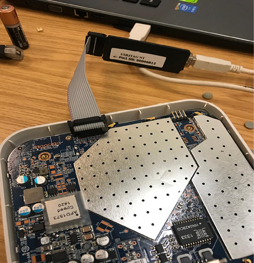
Figure 14.3: USB JTAG NT cable connecting to the Cisco Meraki router
Since USB JTAG NT heavily relies on QTLib libraries, to successfully run this tool on Kali Linux, the following steps are involved:
- Download the USB JTAG NT from https://www.usbjtag.com/filedownload/usbjtagnt-for-linux64.php.
- Download the QTLib from https://www.usbjtag.com/filedownload/library-for-linux64.php.
- Unzip the archive files by running
tar xvf <nameofthefile.tar>. - Ensure you set the QT library path by running
export LD_LIBRARY_PATH=/home/kali/Downloads/QtLib(if you have downloaded the files to a different folder ensure that reflects in the path). - Finally, launch the application by running
./USBJTAGNTin the terminal. Then, you should successfully be able to launch the application without any problems, as shown in Figure 14.4:
Figure 14.4: Successfully loading USB JTAG NT in Kali Linux
Once you select the Category, Protocol type, and Target select, we will set Router as the Category, EJTAG as the Protocol, and then select the model of the router for the target. We will utilize OpenWRT to load into the hardware. If the connected JTAG physically works fine, then we are good to debug the device, as shown in Figure 14.5:

Figure 14.5: Flushing and installing OpenWRT to the device
The program command is utilized to flush the OEM (Original Equipment Manufacturer) operating system. Once the program is complete, we can upload a new .bin file to the device, which will load OpenWRT to the selected router and have full privileges.
Once the flush is complete and OpenWRT is loaded, we can verify the communication to the device by direct SSH access root privileges by running ssh [email protected] from the Kali Linux terminal.
With Windows, you can utilize PuTTY to access the device with default gateway IP (192.168.1.1) as shown in Figure 14.6 (ensure you have a physical Ethernet cable connected to your router and laptop and set a static IP to your device):

Figure 14.6: Connecting to the device using PuTTY to the Meraki wireless access point with root and no password
Introduction to RouterSploit Framework
Similar to the Metasploit Framework, Threat9’s (https://www.threat9.com) RouterSploit Framework is an open-source exploitation framework used to exploit embedded devices (specifically routers). The tool can be installed on Kali by running sudo apt install routersploit from the terminal. The latest version of RouterSploit is 3.4.1, and it comes with 132 known exploits and 4 different scanners, depending on the device type. This entire section can be performed by a mobile device as we know we can install the Kali on any Android phone as described in the Kali on Android (non-rooted phones) section in Chapter 1, Goal-Based Penetration Testing.
The following are the modules of RouterSploit:
exploits: A module that contacts all the identified vulnerabilitiescreds: A module to test for login credentials with predefined usernames and passwordsscanners: A module that runs the scanning with the preconfigured list of vulnerabilitiespayloads: A module to generate payloads according to the device typegeneric/encoders: A module that includes the generic payloads and encoders
In the following example, we will go ahead and use RouterSploit’s scanner function to identify if the router (DLink) that we have connected to is vulnerable to any known vulnerabilities or not. We will use scanners/autopwn against our router that is running on 192.168.0.1, as shown in Figure 14.7:

Figure 14.7: Using Routersploit to exploit a DLink router
The scanner will run 132 exploits from the exploits module. Since we have utilized autopwn, by the end of the scan you should be able to see the list of vulnerabilities that our router is vulnerable to, as shown in Figure 14.8:

Figure 14.8: Output of the autopwn module with a list of exploitable vulnerabilities
Once autopwn is run, you should be able to see the vulnerabilities that can be exploited. In this case, we know the device is vulnerable to two different exploits, so let’s go ahead and use the exploit by running:
use exploits/routers/dlink/dir_300_320_600_615_info_disclosure
set port 80
run
This exploit does Local File Inclusion (LFI) and reaches the httaccess file and extracts the username and password. A successful exploit should result in login information, as shown in Figure 14.9:
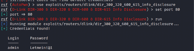
Figure 14.9: Successfully extracting the password from the router using RouterSploit
Let’s try the other vulnerability to bypass the authentication, without having to log in with valid credentials by manipulating the URLs. We can exploit the router by running routersploit, as shown in Figure 14.10; in the case of a router running on port 443, set the ssl value to true:
use exploits/routers/dlink/dir_300_320_615_auth_bypass
run

Figure 14.10: Running the authentication bypass module in RouterSploit
Finally, the URL can be utilized to access the router web interface, which will allow direct access to the setup page, as shown in Figure 14.11:
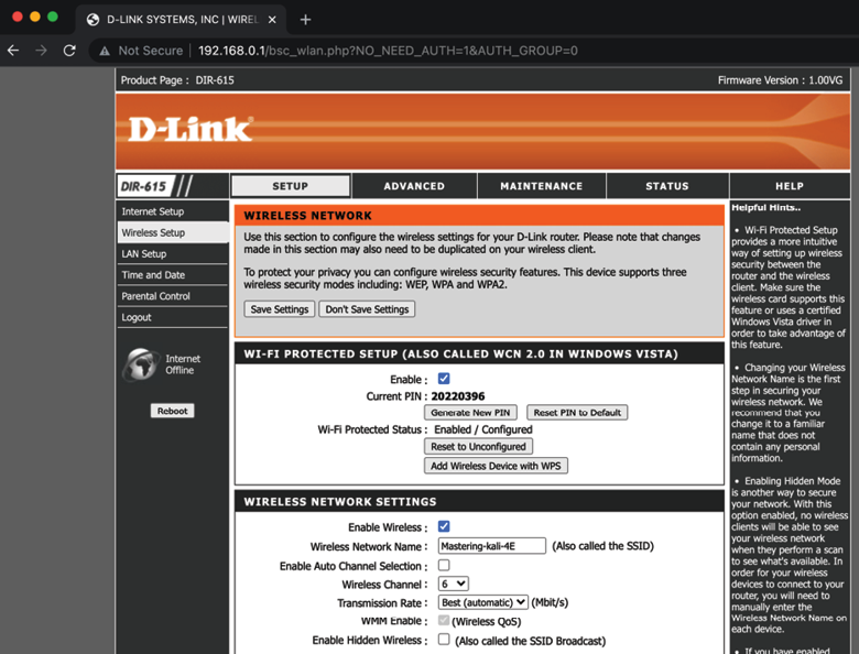
Figure 14.11: Accessing the router settings without any authentication
We have explored RouterSploit to take advantage of the vulnerable routers. Attackers can use a simple non-rooted Android device to perform these attacks.
If you’re tasked to perform hardware pen testing on a newly designed hardware, the following section provides a brief methodology that can be used by attackers to get a root shell on a router using a UART device.
UART
UART stands for Universal Asynchronous Receiver/Transmitter. It is one of the first modes of communication to computers. It goes back to 1960 when it was used to connect minicomputers for teletypewriter machines (teletypes). The main purpose of UARTs is to transmit and receive the serial data just like a standalone integrated circuit; it is not a protocol like SPI (Serial Peripheral Interface) or I2C (Inter-Integrated Circuit). It is typically used by manufacturers to connect microcontrollers to store and load programs. Every UART device has advantages and disadvantages. The following are the advantages of UART:
- It has only two wires, so it’s pretty straightforward. One is transmit (TX), and the other is receive (RX).
- There is no need for a clock signal.
- Error checking can be performed by a parity bit.
- If both sides are set up, then the structure of the data packet can be changed.
- It’s widely used due to the availability of its documentation throughout the internet.
It has the following limitations:
- Testers cannot increase the data frame: it will be limited to 9 bits at most
- There is no way to set up multiple slave or master systems
- UART baud rates must be within 10%
In this section, we will be using the USB to TTL (Transistor/Transistor Logic) adapter to perform UART communication by connecting to the serial port of the device’s circuit board.
These adapters typically include four ports:
- GND: Ground (0V) supply
- VCC: Voltage power supply, 3.3V (default) or 5V
- TX: Serial transmit
- RX: Serial receive
One big challenge attackers face during a hardware hack is to identify the right serial ports. This could be done by using a multimeter to read the voltage output to confirm the TX (typically, the voltage will keep fluctuating when the device is powered on), RX (initially it will fluctuate, but will be constant after a point), and GND (zero voltage).
In this example, we will use a well-known wireless access point (Cisco Meraki MR18) and connect the UART to the TTL device to communicate to the hardware directly, as shown in Figure 14.12:

Figure 14.12: Connecting the UART to Cisco Meraki MR18 wireless access point
When the right TX/RX and ground are identified (to identify the right UART pins, look for 3 or 4 pins next to each other; however, this might change based on the type of device), we can use Kali Linux to learn about the device that is currently connected by running the baudrate.py Python file (https://github.com/PacktPublishing/Mastering-Kali-Linux-for-Advanced-Penetration-Testing-4E/blob/main/Chapter%2014/Baudrate.py).
If the serial device is connected, you should be able to see the following screen in your Kali without any issues. Most of the time, configuring a baud rate of 115,200 works for routers:

Figure 14.13: Successfully connecting to the device with a 115,200 baud rate using the Python script
Once the device is successfully read by our Kali Linux, we can start interacting with the device by running screen /dev/ttyUSB0 115200 in the command line, which should directly provide shell access, as shown in Figure 14.14. Testers have to note that in this example, we have used a known router that provides straight root access, which might not be the same with other devices. Devices manufactured recently will prompt a user to enter their username and password:

Figure 14.14: Accessing the device using the screen command
It is always useful to understand a device from the debug logs: we have seen hardcoded credentials in plenty of IoT devices. We have learned how to connect to a device using a UART cable and communicate to the device as a highly privileged user. In the next section, we will explore cloning an RFID, which can be utilized during physical pen testing or a red team exercise.
Cloning RFID using ChameleonMini
RFID stands for Radio Frequency Identification, which utilizes radio waves to identify items. At a minimum, the RFID system contains a tag, a reader, and an antenna. There are active and passive RFID tags. Active RFID tags contain their own power source, giving them the ability to broadcast with a read range of up to 100 meters. Passive RFID tags do not have their own power source. Instead, they are powered by electromagnetic energy transmitted from the RFID reader.
NFC stands for Near-Field Communication, which is a subset of RFID but with a high frequency. Both NFC and RFID operate at 13.56 MHz. NFC is also designed to run as an NFC reader and NFC tag, which is a unique feature of NFC devices that allows them to communicate with peers. In this section, we will explore one of the devices that comes in handy during physical pen testing/social engineering or a red team exercise to achieve a set objective. For example, if you are signed up to showcase the real threats of an organization that includes gaining access to an organization’s office premises or data centers or boardrooms, you can use ChameleonMini to store six different UIDs in a credit-card-sized portable device:

Figure 14.15: ChameleonMini device/card cloner
The ChameleonMini is a device created by ProxGrind, designed to analyze the security issues around NFC to emulate and clone contactless cards, read RFID tags, and also sniff RF data. For developers, it is freely programmable. This device can be purchased online at https://lab401.com/. In this example, we have used ProxGrind ChameleonMini RevG to demonstrate cloning a UID.
In Kali Linux, we can validate the device by directly connecting with the USB. The lsusb command should display the ChameleonMini as MCS, and every serial device connected to Kali Linux will be listed in /dev/. In this case, our device is visible as a serial port named ttyACM0, as shown in Figure 14.16:

Figure 14.16: Identifying the device in Kali Linux
We can communicate with the serial port directly using picocom by running picocom --baud 115200 --echo /dev/ttyACM0 as shown in Figure 14.17. picocom can be installed by running apt-get install picocom:

Figure 14.17: Connecting to the device using picocom at a baud rate of 115,200
You will require the card that you want to clone. You can use a one-step action to clone the card by placing it on the ChameleonMini. Type CLONE and the job is done, as shown in Figure 14.18:

Figure 14.18: Successfully cloning a card with the configuration
The following details provide the manual way of doing it:
- Using the command line, do the following:
- Once the serial port communication is established between Kali Linux and the device, type the
HELPcommand to display all the available commands for ChameleonMini. - ChameleonMini comes with eight slots, each of which can act as an individual NFC card. The slots can be set by using the
SETTINGS=command. For example, we can set the slot to2by typing thesettings=2command; it should return100:OK. - Run
CONFIG?to see the current configuration. The new device should return the following:101:OK WITH TEXT NONE
- Once the serial port communication is established between Kali Linux and the device, type the
- The next step is to place the card reader into reader mode. This can be achieved by typing
CONFIG=ISO14443A_READER. - Now we can place the card that needs to be cloned in the card reader and type the
Identifycommand. - Once you identify the type of the card, you can set the configuration using the
CONFIGcommand: in our case, it is MIFARE Classic 1K, so we will runCONFIG=MF_CLASSIC_1K. - Now we have set the configuration, we can steal the UID from the card and then add it to our ChameleonMini by running
UID=CARD NUMBER, as shown in Figure 14.19:
Figure 14.19: Cloning the card manually
- We are now all set to use the ChameleonMini as a card.
- Pentesters can also pre-program this to perform the cloning tasks with the use of two buttons on the device while on the move. For example, during social engineering, while the testers talk to the victim company’s staff, they click the button and clone their (NFC) ID cards. This can be performed by the following commands:
LBUTTON=CLONE: This will set a click of the left-hand button to clone the card.RBUTTON=CYCLE_SETTINGS: This will set a click of the right button to rotate the slots. For example, if CARD A is cloned to slot 1 and you wanted to clone another card, this can be performed by clicking the right-hand button, which will move the CARD A details to slot 2. Then, you can go ahead and press the left-hand button to clone the new card.
Other tools
There are other tools, such as HackRF One, which is a software-defined radio that can also be utilized by pentesters to perform any kind of radio sniffing or transmission of your own signals, or even replay the captured radio packets.
We will take a brief example of sniffing a radio frequency in Kali Linux using HackRF One SDR. HackRF libraries need to be installed by running sudo apt install hackrf gqrx-sdr in the terminal. Testers should be able to identify the device by running sudo hackrf_info from the terminal. If the device is recognized, you should be able to see the following screenshot with the details of firmware, part ID, and so on:
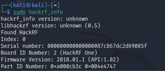
Figure 14.20: Reading the HackRF device in Kali Linux
Pentesters can utilize the kalibrate tool to scan any GSM base stations. This tool can be downloaded from https://github.com/scateu/kalibrate-hackrf and can be built using the following commands:
git clone https://github.com/scateu/kalibrate-hackrf
cd kalibrate-hackrf
./bootstrap
./configure
./make && make install
Once the installation is complete, sudo kal will be the tool to utilize to scan a specific band. We will be utilizing the root terminal to run the commands since it has to invoke the hardware, and we can run the tool by mentioning the frequency (kal –s GSM900), as shown in Figure 14.21:

Figure 14.21: Scanning the GSM channels using HackRF within Kali Linux
If the testers can identify the type of peripherals during an on-site assessment and find that the company is utilizing certain vulnerable hardware, then they can also utilize Crazyradio PA, a long-range 2.4 GHz USB radio dongle that can deliver a payload to any computer that is using the vulnerable device through radio wireless signals.
Summary
In this chapter, we took a quick journey into basic embedded systems and their architecture, and we learned about different types of firmware, bootloaders, UART, radio sniffing, and common tools that can be utilized during hardware hacking. We also learned how to unpack firmware and load new firmware on a router using USB JTAG NT. Additionally, we explored using RouterSploit to identify the specific vulnerabilities in the embedded devices. Finally, we learned how to clone a physical RFID/NFC card using a ChameleonMini, which can be utilized during red teaming exercises.
We hope this book has helped you to understand the fundamental risks and how attackers use these tools to compromise networks/devices within a few seconds, and how you can use the same tools and techniques to understand your infrastructure’s vulnerabilities, as well as the importance of remediation and patch management before your own infrastructure is compromised. On that note, this chapter concludes Mastering Kali Linux for Advanced Penetration Testing – Fourth Edition.