
Fastenings
4.1 Screwed fastenings
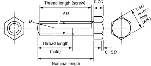
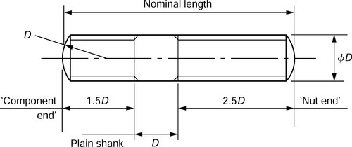
4.1.1 Drawing proportions
Bolts and screws
Studs
Standard nut

Thin (lock) nut

Plain washer

4.1.2 Alternative screw heads

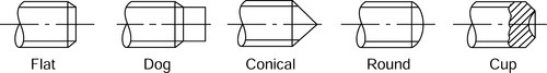
4.1.3 Alternative screw points
4.1.4 Hexagon socket cap head screw

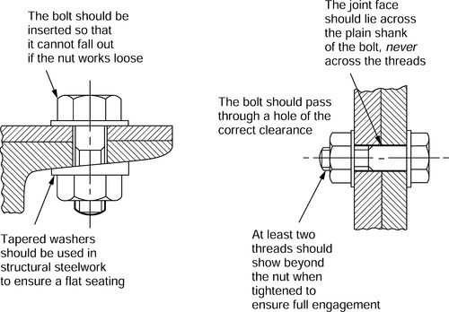
4.1.5 Applications of screwed fasteners
4.1.6 Acme thread form

4.1.7 Square thread form

4.1.8 Buttress thread form

4.1.9 V-thread form

4.1.10 Basic Whitworth (55°) thread form: parallel threads

This is the basic thread form for BSW, BSF and BSP screw threads.
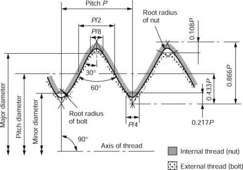
4.1.11 ISO metric and ISO 60° unified thread forms
4.1.12 Introduction to screwed fasteners
Although dimensioned in °inch° units the following screw thread tables (Sections 4.1.38 to 4.1.43) have been retained for maintenance data and similar applications. Screwed fasteners to these specifications are still manufactured:
4.1.38 British Standard Whitworth (BSW) bolts and nuts
4.1.39 British Standard Fine (BSF) bolts and nuts
4.1.40 ISO unified precision internal screw threads: coarse series (UNC)
4.1.41 ISO unified precision external screw threads: coarse series (UNC)
4.1.42 ISO unified precision internal screw threads: fine series (UNF)
4.1.43 ISO unified precision external screw threads: fine series (UNF)
Although obsolescent the following screw thread table (Section 4.1.45) has been retained for the reasons given above:
4.1.45 British Association (BA) internal and external screw threads
The tables based on abstracts from the BS EN 24 000 series have been replaced by the current BS EN ISO 4000 series for screwed fasteners with metric dimensions. These new standards (Sections 4.1.13 to 4.1.21) are as follows:
4.1.13 BS EN ISO 4014: 2001 Hexagon head bolts - product grades A and B
4.1.14 BS EN ISO 4016: 2001 Hexagon head bolts - product grade C
4.1.15 BS EN ISO 4017: 2001 Hexagon head screws - product grades A and B
4.1.16 BS EN ISO 4018: 2001 Hexagon head screws - product grade C
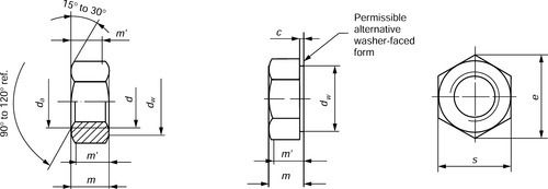
4.1.17 BS EN ISO 4032: 2001 Hexagon nuts style 1 - product grades A and B
4.1.18 BS EN ISO 4033: 2001 Hexagon nuts style 2 - product grades A and B
4.1.19 BS EN ISO 4034: 2001 Hexagon nuts style 1 - product grade C
4.1.20 BS EN ISO 4035: 2001 Hexagon thin nuts (chamfered) - product grades A and B
4.1.21 BS EN ISO 4036: 2001 Hexagon thin nuts (unchamfered) - product grade B
All the above standards refer to screwed fasteners with metric dimensions that have coarse pitch threads. Fine pitch threads will be referred to in due course.
Note:
(i) BS EN ISO 4015 refers to hexagon head bolts with their shanks reduced to the effective (pitch) diameter of their threads. These are for specialized applications and have not been included in this pocket book.
(ii) The mechanical property standards that were contained within BS 4190 and BS 3692 can now be found in BS EN 20898 Part 1 (bolts) and Part 2 (nuts.
Interpretation of the product grade is as follows:
• Examine the table in Section 4.1.13.
• The shank diameter (ds) has a maximum diameter which equals 80 mm, the nominal diameter and also the minimum diameter.
• The minimum diameter can have a product grade A tolerance or a product grade B tolerance. The grade A tolerance is closer (more accurate) than the grade B tolerance.
• Product grade A tolerances apply to fasteners with a size range from M1.6 to M24 inclusive.
• Product grade B tolerances apply to fasteners with a size range from M16 to M64.
• Therefore sizes M16 to M24 inclusive can have product grade A or B tolerances and the required tolerance must be specified.
• Note that the product grade is not only influenced by the diameter but also by the length as well.
Example 1
An M5 hexagon head bolt will lie within product grade A tolerances and will have a shank diameter lying between 5.00 and 4.82 mm inclusive.
Example 2
An M36 hexagon head bolt will lie within product grade B tolerances and will have a shank diameter lying between 36.00 and 35.38 mm inclusive.
Example 3
An M16 hexagon head bolt will have a shank diameterlying between 16 and 15.73 mm inclusive if it is toproduct grade A tolerances. If it is to product grade B tolerances, it will have a shank diameter lying between 16 and 15.57 mm inclusive.
Note: The above system of tolerancing applies to all the other dimensions for the fasteners in these tables:
• Examine the table in Section 4.1.14. All the dimensions in this table refer to screwed fasteners with product grade C tolerances. Comparing this table with the previous examples shows that the fasteners made to the product grade C specifications have much coarser tolerances than those manufactured to product grades A and B tolerances.
• An M12 bolt to product grade A has a shank diameter(cQ lying between 12 and11. 73 mm (a tolerance of 0.27 mm), whereas an M12 bolt made product grade C will have a shank diameter (ds) lying between 12.77 and 11.3 mm (a tolerance of 1.4 mm). Product grade B does not apply to this size of bolt.
Note: The old terminology of 'black' (hot forged) and 'bright/precision' (cold headed or machined from hexagon bar) bolts and nuts no longer applies. However hot forged (black) bolts and nuts made to special order would only have been made to product grade C.
All the previous notes refer to hexagon head bolts,screws and nuts with coarse pitch threads. Bolts have a plain shank between the thread and the head, whereas a screw is threaded virtually all the way up to the head. The following tables and standards (Sections 4.1.22 to 4.1.26) refer to a corresponding fine pitch series of screwed fasteners. These fine pitch series of screwed fasteners are only available in product grades A and B.
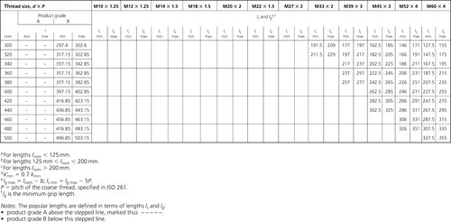
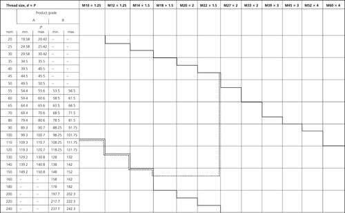
4.1.22 BS EN ISO 8765: 2001 Hexagon head bolts with metricfine pitch threads - product grades A and B
4.1.23 BS EN ISO 8676: 2001 Hexagon head screws with metric fine pitch threads - product grades A and B
4.1.24 BS EN ISO 8673: 2001 Hexagon nuts style 1 with metric fine pitch threads - product grades A and B
4.1.25 BS EN ISO 8674: 2001 Hexagon nuts style 2 with metric fine pitch threads -product grades A and B
4.1.26 BS EN ISO 8675: 2001 Hexagon thin nuts with metric fine pitch threads - product grades A and B
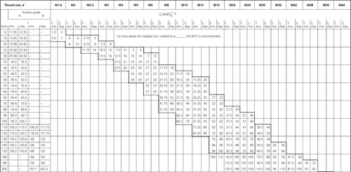
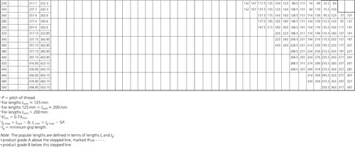
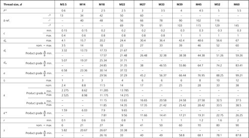
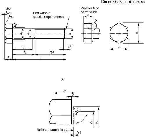
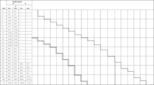
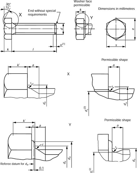
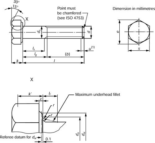
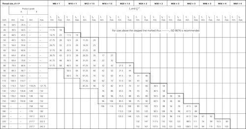
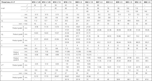
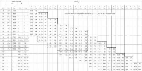
4.1.13 BS EN ISO 4014: 2001 Hexagon head bolts - product grades A and B
Dimensions
Note: Symbols and descriptions of dimensions are specified in ISO 225.
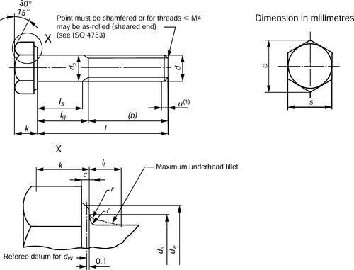
(1) Incomplete thread u ≤ 2 P
Example for the designation of a hexagon head bolt with thread M12, nominal length I = 80 mm and property class 8.8:
Hexagon head bolt ISO 4014 - M12 ×80 - 8.8


4.1.14 BS EN ISO 4016: 2001 Hexagon head bolts - product grade C
Dimensions
Note: Symbols and descriptions of dimensions are specified in ISO 225.
(1) Incomplete thread u ≤ 2 P
Example for the designation of a hexagon head bolt with thread M12, nominal length l = 80 mm and property class 4.6:
Hexagon head bolt ISO 4016 - M12 x 80 - 4.6
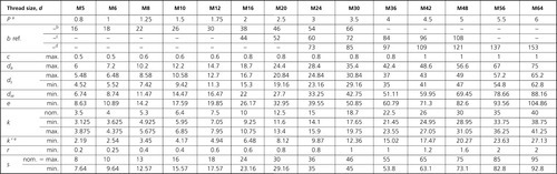


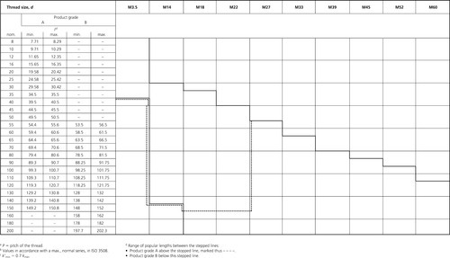
4.1.15 BS EN ISO 4017: 2001 Hexagon head screws - product grades A and B
Dimensions
Note: Symbols and descriptions of dimensions are specified in ISO 225.

(1) Incomplete thread u ≤ 2 P.
(2) ds = pitch diameter.
Example for the designation of a hexagon head screwwith thread size M12, nominal length I= 80 mm and property class 8.8:
Hexagon head screw ISO 4017- M12 x80 –8.8


4.1.16 BS EN ISO 4018: 2001 Hexagon head screws - product grade C
Dimensions
Note: Symbols and descriptions of dimensions are specified in ISO 225.
Example for the designation of a hexagon head screw with thread size M12, nominal length I= 80 mm and property class 4.6:
Hexagon head screw ISO 4018- M12x 80 –4.6


4.1.17 BS EN ISO 4032: 2001 Hexagon nuts style 1 - product grades A and B
Dimensions

Example for the designation of a hexagon nut, style1, with thread size d = M12 and property class 8:
Hexagon nut ISO 4032 - M12 - 8
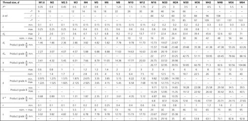
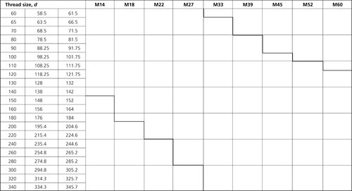
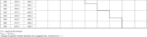
BS EN ISO 4032: 2001 Table 1
Preferred sizes
| Thread size, d | M1.6 | M2 | M2.5 | M3 | M4 | M5 | M6 | M8 | M10 | M12 | |
| Pa | 0.35 | 0.4 | 0.45 | 0.5 | 0.7 | 0.8 | 1 | 1.25 | 1.5 | 1.75 | |
| c | max. | 0.2 | 0.2 | 0.3 | 0.4 | 0.4 | 0.5 | 0.5 | 0.6 | 0.6 | 0.6 |
| min. | 0.1 | 0.1 | 0.1 | 0.15 | 0.15 | 0.15 | 0.15 | 0.15 | 0.15 | 0.15 | |
| da | min. | 1.6 | 2 | 2.5 | 3 | 4 | 5 | 6 | 8. | 10 | 12 |
| max. | 1.84 | 2.3 | 2.9 | 3.45 | 4.6 | 5.75 | 6.75 | 8.75 | 10.8 | 13 | |
| dw | min. | 2.4 | 3.1 | 4.1 | 4.6 | 5.9 | 6.9 | 8.9 | 11.6 | 14.6 | 16.6 |
| e | min. | 3.41 | 4.32 | 5.45 | 6.01 | 7.66 | 8.79 | 11.05 | 14.38 | 17.77 | 20.03 |
| m | max. | 1.3 | 1.6 | 2 | 2.4 | 3.2 | 4.7 | 5.2 | 6.8 | 8.4 | 10.8 |
| min. | 1.05 | 1.35 | 1.75 | 2.15 | 2.9 | 4.4 | 4.9 | 6.44 | 8.04 | 10.37 | |
| m' | min. | 0.8 | 1.1 | 1.4 | 1.7 | 2.3 | 3.5 | 3.9 | 5.2 | 6.4 | 8.3 |
| m" | min. | 0.7 | 1 | 1.2 | 1.5 | 2 | 3.1 | 3.4 | 4.5 | 5.6 | 7.3 |
| s | nom. = max. | 3.2 | 4 | 5 | 5.5 | 7 | 8 | 10 | 13 | 16 | 18 |
| min. | 3.02 | 3.82 | 4.82 | 5.32 | 6.78 | 7.78 | 9.78 | 12.73 | 15.73 | 17.73 | |
| Thread size, d | M16 | M20 | M24 | M30 | M36 | M42 | M48 | M56 | M64 | ||
| Pa | 2 | 2.5 | 3 | 3.5 | 4 | 4.5 | 5 | 5.5 | 6 | ||
| c | max. | 0.8 | 0.8 | 0.8 | 0.8 | 0.8 | 1 | 1 | 1 | 1 | |
| min. | 0.2 | 0.2 | 0.2 | 0.2 | 0.2 | 0.3 | 0.3 | 0.3 | 0.3 | ||
| da | min. | 16 | 20 | 24 | 30 | 36 | 42 | 48 | 56 | 64 | |
| max. | 17.3 | 21.6 | 25.9 | 32.4 | 38.9 | 45.4 | 51.8 | 60.5 | 69.1 | ||
| dw | min. | 22.5 | 27.7 | 33.3 | 42.8 | 51.1 | 60 | 69.5 | 78.7 | 88.2 | |
| e | min. | 26.75 | 32.95 | 39.55 | 50.85 | 60.79 | 71.3 | 82.6 | 93.56 | 104.86 | |
| m | max. | 14.8 | 18 | 21.5 | 25.6 | 31 | 34 | 38 | 45 | 51 | |
| min. | 14.1 | 16.9 | 20.2 | 24.3 | 29.4 | 32.4 | 36.4 | 43.4 | 49.1 | ||
| m' | min. | 11.3 | 13.5 | 16.2 | 19.4 | 23.5 | 25.9 | 29.1 | 34.7 | 39.3 | |
| m" | min. | 9.9 | 11.8 | 14.1 | 17 | 20.6 | 22.7 | 25.5 | 30.4 | 34.4 | |
| nom. = max. | 24 | 30 | 36 | 46 | 55 | 65 | 75 | 85 | 95 | ||
| s | min. | 23.67 | 29.16 | 35 | 45 | 53.8 | 63.1 | 73.1 | 82.8 | 92.8 | |
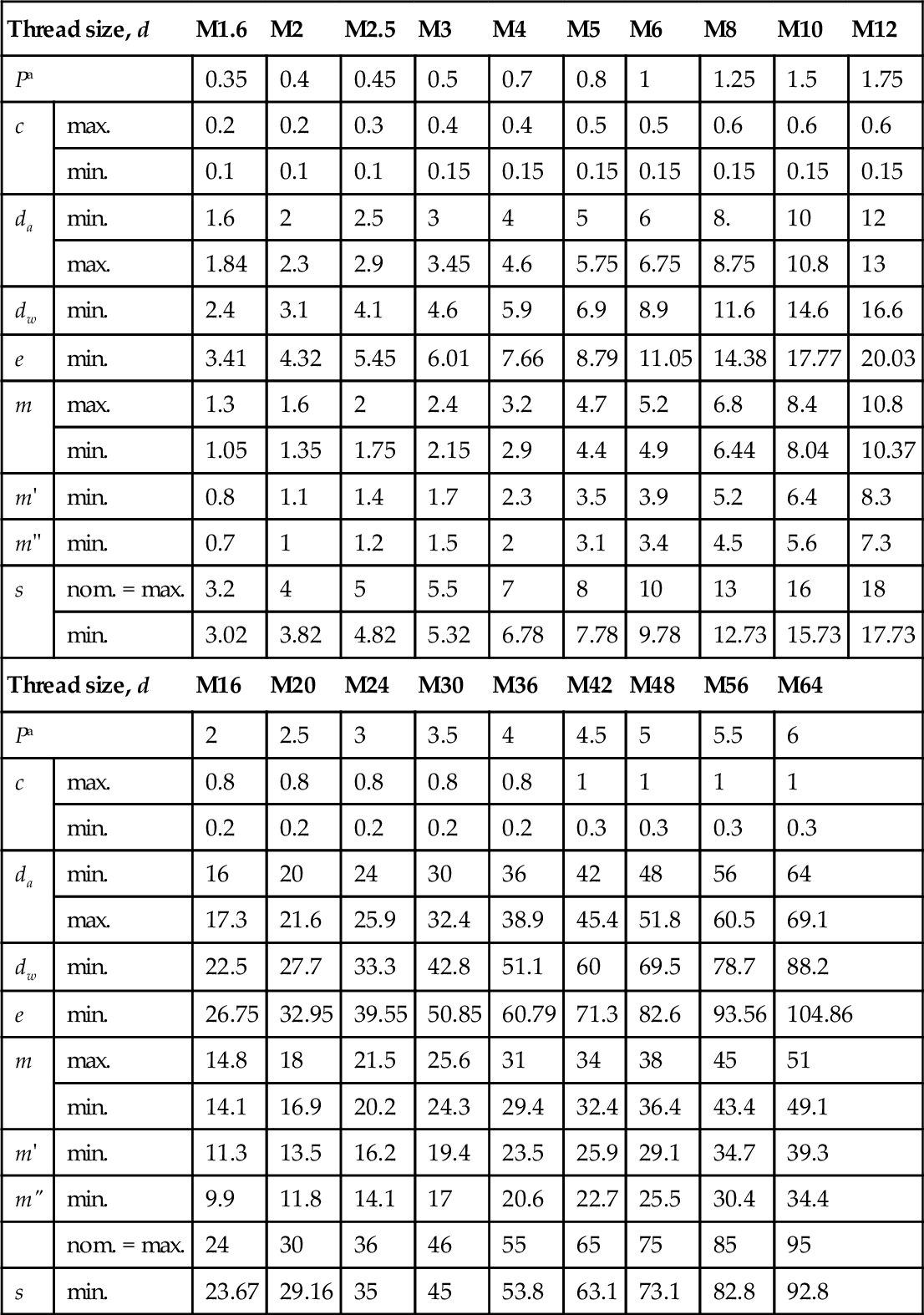
aP = pitch of the thread.
BS EN ISO 4032: 2001 Table 2
Non − preferred sizes
| Thread size, d | M3.5 | M14 | M18 | M22 | M27 | M33 | M39 | M45 | M52 | M60 | |
| Pa | 0.6 | 2 | 2.5 | 2.5 | 3 | 3.5 | 4 | 4.5 | 5 | 5.5 | |
| c | max. | 0.4 | 0.6 | 0.8 | 0.8 | 0.8 | 0.8 | 1 | 1 | 1 | 1 |
| min. | 0.15 | 0.15 | 0.2 | 0.2 | 0.2 | 0.2 | 0.3 | 0.3 | 0.3 | 0.3 | |
| da | min. | 3.5 | 14 | 18 | 22 | 27 | 33 | 39 | 45 | 52 | 60 |
| max. | 4 | 15.1 | 19.5 | 23.7 | 29.1 | 35.6 | 42.1 | 48.6 | 56.2 | 64.8 | |
| dw | min. | 5 | 19.6 | 24.9 | 31.4 | 38 | 46.6 | 55.9 | 64.7 | 74.2 | 83.4 |
| e | min. | 6.58 | 23.35 | 29.56 | 37.29 | 45.2 | 55.37 | 66.44 | 76.95 | 88.25 | 99.21 |
| m | max. | 2.8 | 12.8 | 15.8 | 19.4 | 23.8 | 28.7 | 33.4 | 36 | 42 | 48 |
| min. | 2.55 | 12.1 | 15.1 | 18.1 | 22.5 | 27.4 | 31.8 | 34.4 | 40.4 | 46.4 | |
| m' | min. | 2 | 9.7 | 12.1 | 14.5 | 18 | 21.9 | 25.4 | 27.5 | 32.3 | 37.1 |
| m" | min. | 1.8 | 8.5 | 10.6 | 12.7 | 15.8 | 19.2 | 22.3 | 24.1 | 28.3 | 32.5 |
| nom. = max. | 6 | 21 | 27 | 34 | 41 | 50 | 60 | 70 | 80 | 90 | |
| s | min. | 5.82 | 20.67 | 26.16 | 33 | 40 | 49 | 58.8 | 68.1 | 78.1 | 87.8 |
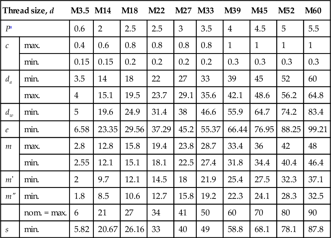
a P = pitch of the thread.
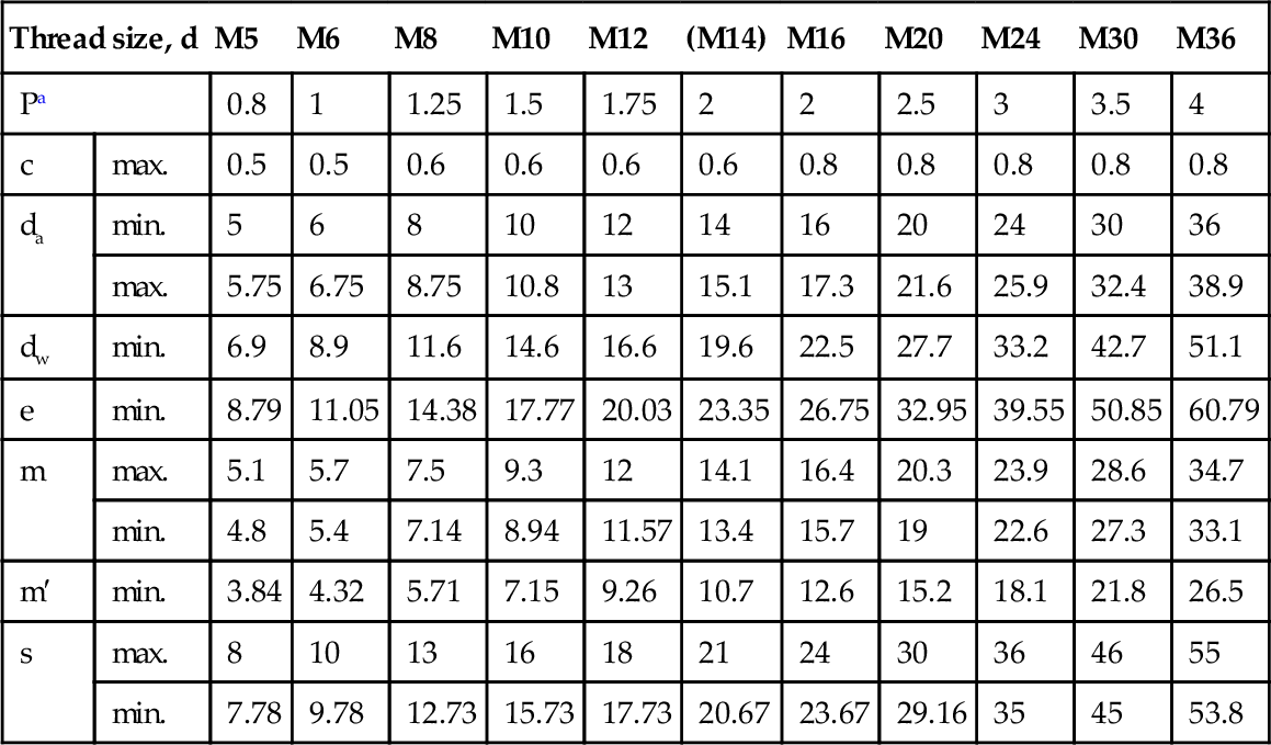
4.1.18 BS EN ISO 4033: 2001 Hexagon nuts style 2 - product grades A and B
Dimensions
Example for the designation of a hexagon nut with metric thread size d = M12 and property class 9:
Hexagon nut ISO 4033 - M12 - 9
Dimensions in mm
| Thread size, d | M5 | M6 | M8 | M10 | M12 | (M14) | M16 | M20 | M24 | M30 | M36 | |
| Pa | 0.8 | 1 | 1.25 | 1.5 | 1.75 | 2 | 2 | 2.5 | 3 | 3.5 | 4 | |
| c | max. | 0.5 | 0.5 | 0.6 | 0.6 | 0.6 | 0.6 | 0.8 | 0.8 | 0.8 | 0.8 | 0.8 |
| da | min. | 5 | 6 | 8 | 10 | 12 | 14 | 16 | 20 | 24 | 30 | 36 |
| max. | 5.75 | 6.75 | 8.75 | 10.8 | 13 | 15.1 | 17.3 | 21.6 | 25.9 | 32.4 | 38.9 | |
| dw | min. | 6.9 | 8.9 | 11.6 | 14.6 | 16.6 | 19.6 | 22.5 | 27.7 | 33.2 | 42.7 | 51.1 |
| e | min. | 8.79 | 11.05 | 14.38 | 17.77 | 20.03 | 23.35 | 26.75 | 32.95 | 39.55 | 50.85 | 60.79 |
| m | max. | 5.1 | 5.7 | 7.5 | 9.3 | 12 | 14.1 | 16.4 | 20.3 | 23.9 | 28.6 | 34.7 |
| min. | 4.8 | 5.4 | 7.14 | 8.94 | 11.57 | 13.4 | 15.7 | 19 | 22.6 | 27.3 | 33.1 | |
| m′ | min. | 3.84 | 4.32 | 5.71 | 7.15 | 9.26 | 10.7 | 12.6 | 15.2 | 18.1 | 21.8 | 26.5 |
| s | max. | 8 | 10 | 13 | 16 | 18 | 21 | 24 | 30 | 36 | 46 | 55 |
| min. | 7.78 | 9.78 | 12.73 | 15.73 | 17.73 | 20.67 | 23.67 | 29.16 | 35 | 45 | 53.8 | |
Sizes in brackets should be avoided if possible.
a P = pitch of the thread.

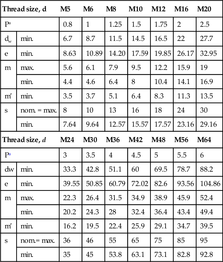
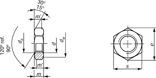
4.1.19 BS EN ISO 4034: 2001 Hexagon nuts style 1 - product grade C
Dimensions
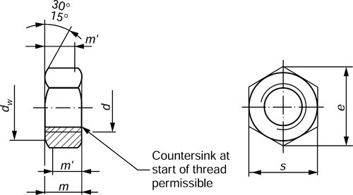
Example for the designation of a hexagonnut with thread size d = M12 and property class 5:
Hexagon nut ISO 4034 – M12 – 5
Dimensions in mm
BS EN ISO 4034: 2001 Table 1
Preferred sizes
| Thread size, d | M5 | M6 | M8 | M10 | M12 | M16 | M20 | |
| Pa | 0.8 | 1 | 1.25 | 1.5 | 1.75 | 2 | 2.5 | |
| dw | min. | 6.7 | 8.7 | 11.5 | 14.5 | 16.5 | 22 | 27.7 |
| e | min. | 8.63 | 10.89 | 14.20 | 17.59 | 19.85 | 26.17 | 32.95 |
| m | max. | 5.6 | 6.1 | 7.9 | 9.5 | 12.2 | 15.9 | 19 |
| min. | 4.4 | 4.6 | 6.4 | 8 | 10.4 | 14.1 | 16.9 | |
| m′ | min. | 3.5 | 3.7 | 5.1 | 6.4 | 8.3 | 11.3 | 13.5 |
| s | nom. = max. | 8 | 10 | 13 | 16 | 18 | 24 | 30 |
| min. | 7.64 | 9.64 | 12.57 | 15.57 | 17.57 | 23.16 | 29.16 | |
| Thread size, d | M24 | M30 | M36 | M42 | M48 | M56 | M64 | |
| Pa | 3 | 3.5 | 4 | 4.5 | 5 | 5.5 | 6 | |
| dw | min. | 33.3 | 42.8 | 51.1 | 60 | 69.5 | 78.7 | 88.2 |
| e | min. | 39.55 | 50.85 | 60.79 | 72.02 | 82.6 | 93.56 | 104.86 |
| m | max. | 22.3 | 26.4 | 31.5 | 34.9 | 38.9 | 45.9 | 52.4 |
| min. | 20.2 | 24.3 | 28 | 32.4 | 36.4 | 43.4 | 49.4 | |
| m′ | min. | 16.2 | 19.5 | 22.4 | 25.9 | 29.1 | 34.7 | 39.5 |
| s | nom.= max. | 36 | 46 | 55 | 65 | 75 | 85 | 95 |
| min. | 35 | 45 | 53.8 | 63.1 | 73.1 | 82.8 | 92.8 | |
a P = pitch of the thread.
Dimensions in mm
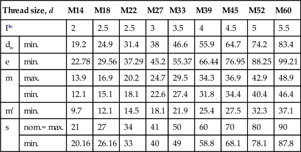
BS EN ISO 4034: 2001 Table 2 Non-preferred sizes
| Thread size, d | M14 | M18 | M22 | M27 | M33 | M39 | M45 | M52 | M60 | |
| Pa | 2 | 2.5 | 2.5 | 3 | 3.5 | 4 | 4.5 | 5 | 5.5 | |
| dw | min. | 19.2 | 24.9 | 31.4 | 38 | 46.6 | 55.9 | 64.7 | 74.2 | 83.4 |
| e | min. | 22.78 | 29.56 | 37.29 | 45.2 | 55.37 | 66.44 | 76.95 | 88.25 | 99.21 |
| m | max. | 13.9 | 16.9 | 20.2 | 24.7 | 29.5 | 34.3 | 36.9 | 42.9 | 48.9 |
| min. | 12.1 | 15.1 | 18.1 | 22.6 | 27.4 | 31.8 | 34.4 | 40.4 | 46.4 | |
| m′ | min. | 9.7 | 12.1 | 14.5 | 18.1 | 21.9 | 25.4 | 27.5 | 32.3 | 37.1 |
| s | nom.= max. | 21 | 27 | 34 | 41 | 50 | 60 | 70 | 80 | 90 |
| min. | 20.16 | 26.16 | 33 | 40 | 49 | 58.8 | 68.1 | 78.1 | 87.8 | |
a P = pitch of the thread.
4.1.20 BS EN ISO 4035: 2001 Hexagon thin nuts (chamfered) - product grades A and B
Dimensions
Dimensions in mm
BS EN ISO 4035: 2001 Table 1 Preferred sizes
| Thread size, d | M16 | M2 | M2.5 | M3 | M4 | M5 | M6 | M8 | M10 | M12 | Thread size, d | M16 | M20 | M24 | M30 | M36 | M42 | M48 | M56 | M64 | ||
| Pa | 0.35 | 0.4 | 0.45 | 0.5 | 0.7 | 0.8 | 1 | 1.25 | 1.5 | 1.75 | Pa | 2 | 2.5 | 3 | 3.5 | 4 | 4.5 | 5 | 5.5 | 6 | ||
| da | min. | 1.6 | 2 | 2.5 | 3 | 4 | 5 | 6 | 8 | 10 | 12 | da | min. | 16 | 20 | 24 | 30 | 36 | 42 | 48 | 56 | 64 |
| max. | 1.84 | 2.3 | 2.9 | 3.45 | 4.6 | 5.75 | 6.75 | 8.75 | 10.8 | 13 | max. | 17.3 | 21.6 | 25.9 | 32.4 | 38.9 | 45.4 | 51.8 | 60.5 | 69.1 | ||
| dw | min. | 2.4 | 3.1 | 4.1 | 4.6 | 5.9 | 6.9 | 8.9 | 11.6 | 14.6 | 16.6 | dw | min. | 22.5 | 27.7 | 33.2 | 42.8 | 51.1 | 60 | 69.5 | 78.7 | 88.2 |
| e | min. | 3.41 | 4.32 | 5.45 | 6.01 | 7.66 | 8.79 | 11.05 | 14.38 | 17.77 | 20.03 | e | min. | 26.75 | 32.95 | 39.55 | 50.85 | 60.79 | 71.3 | 82.6 | 93.56 | 104.86 |
| m | max. | 1 | 1.2 | 1.6 | 1.8 | 2.2 | 2.7 | 3.2 | 4 | 5 | 6 | m | max. | 8 | 10 | 12 | 15 | 18 | 21 | 24 | 28 | 32 |
| min. | 0.75 | 0.95 | 1.35 | 1.55 | 1.95 | 2.45 | 2.9 | 3.7 | 4.7 | 5.7 | min. | 7.42 | 9.10 | 10.9 | 13.9 | 16.9 | 19.7 | 22.7 | 26.7 | 30.4 | ||
| m′ | min. | 0.6 | 0.8 | 1.1 | 1.2 | 1.6 | 2 | 2.3 | 3 | 3.8 | 4.6 | m | min. | 5.9 | 7.3 | 8.7 | 11.1 | 13.5 | 15.8 | 18.2 | 21.4 | 24.3 |
| s | nom.= max. | 3.2 | 4 | 5 | 5.5 | 7 | 8 | 10 | 13 | 16 | 18 | s | nom.= max. | 24 | 30 | 36 | 46 | 55 | 65 | 75 | 85 | 95 |
| min. | 3.02 | 3.82 | 4.82 | 5.32 | 6.78 | 7.78 | 9.78 | 12.73 | 15.73 | 17.73 | min. | 23.67 | 29.16 | 35 | 45 | 53.8 | 63.1 | 73.1 | 82.8 | 92.8 | ||

a P = pitch of the thread.
Dimensions in mm
BS EN ISO 4035: 2001 Table 2 Non-preferred sizes
| Thread size, d | M3.5 | M14 | M18 | M22 | M27 | M33 | M39 | M45 | M52 | M60 | |
| Pa | 0.6 | 2 | 2.5 | 2.5 | 3 | 3.5 | 4 | 4.5 | 5 | 5.5 | |
| da | min. | 3.5 | 14 | 18 | 22 | 27 | 33 | 39 | 45 | 52 | 60 |
| max. | 4 | 15.1 | 19.5 | 23.7 | 29.1 | 35.6 | 42.1 | 48.6 | 56.2 | 64.8 | |
| dw | min. | 5.1 | 19.6 | 24.9 | 31.4 | 38 | 46.6 | 55.9 | 64.7 | 74.2 | 83.4 |
| e | min. | 6.58 | 23.35 | 29.56 | 37.29 | 45.2 | 55.37 | 66.44 | 76.95 | 88.25 | 99.21 |
| m | max. | 2 | 7 | 9 | 11 | 13.5 | 16.5 | 19.5 | 22.5 | 26 | 30 |
| min. | 1.75 | 6.42 | 8.42 | 9.9 | 12.4 | 15.4 | 18.2 | 21.2 | 24.7 | 28.7 | |
| m'. | min. | 1.4 | 5.1 | 6.7 | 7.9 | 9.9 | 12.3 | 14.6 | 17 | 19.8 | 23 |
| s | nom.= max. | 6 | 21 | 27 | 34 | 41 | 50 | 60 | 70 | 80 | 90 |
| min. | 5.82 | 20.67 | 26.16 | 33 | 40 | 49 | 58.8 | 68.1 | 78.1 | 87.8 | |

a P = pitch of the thread.
Example for the designation of a chamfered thin nut with thread size d= M12 and property class 05:
Hexagon thin nut ISO 4035 - M12 - 05
4.1.21 BS EN ISO 4036: 2001 Hexagon thin nuts (unchamfered) - product grade B
Dimensions

Example for the designation of a hexagon thin nut with metric thread d = M6 made from steel with HV 110 min. (st):

4.1.22 BS EN ISO 8765: 2001 Hexagon head bolts with metric fine pitch threads - product grades A and B
Dimensions
Note: Symbols and descriptions of dimensions are specified in ISO 225.
(1) Incomplete thread u ≤ 2 P


4.1.23 BS EN ISO 8676: 2001 Hexagon head screws with metric fine pitch threads - product grades A and B
Dimensions
Note: Symbols and descriptions of dimensions are specified in ISO 225.

(1) Incomplete thread u ≤ 2 P.
(2) ds = pitch diameter.
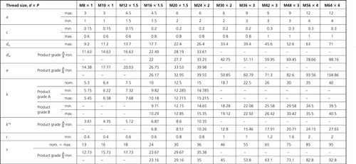


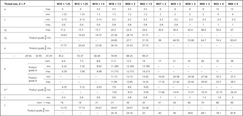

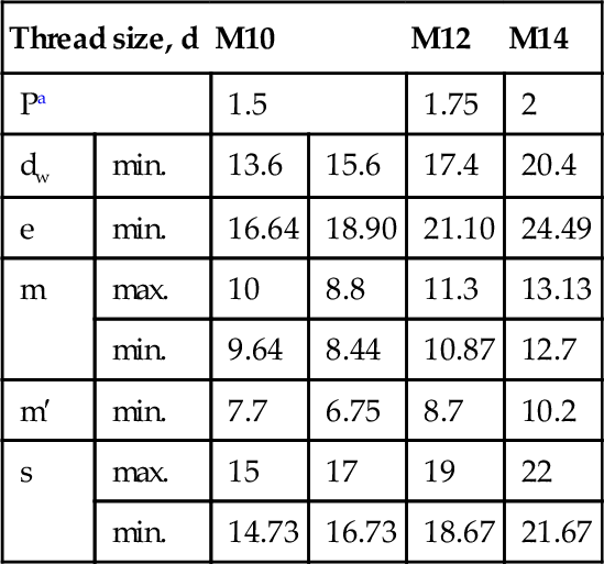
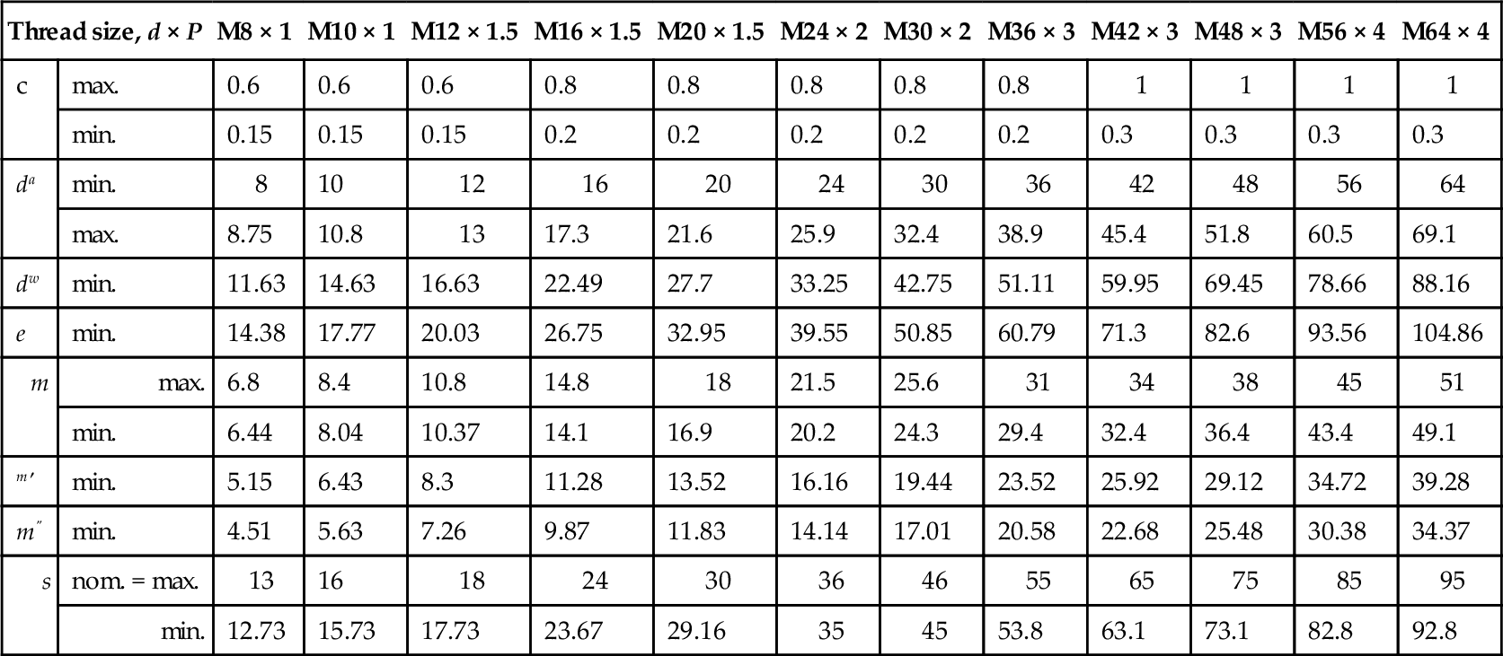
4.1.24 BS EN ISO 8673: 2001 Hexagon nuts style 1 with metric fine pitch threa grades A and B
Dimensions
Note: Symbols and descriptions of dimensions are specified in ISO 225.

BS EN ISO 8673: 2001 Table 1 Preferred threads
| Thread size, d × P | M8 × 1 | M10 × 1 | M12 × 1.5 | M16 × 1.5 | M20 × 1.5 | M24 × 2 | M30 × 2 | M36 × 3 | M42 × 3 | M48 × 3 | M56 × 4 | M64 × 4 | |
| c | max. | 0.6 | 0.6 | 0.6 | 0.8 | 0.8 | 0.8 | 0.8 | 0.8 | 1 | 1 | 1 | 1 |
| min. | 0.15 | 0.15 | 0.15 | 0.2 | 0.2 | 0.2 | 0.2 | 0.2 | 0.3 | 0.3 | 0.3 | 0.3 | |
| da | min. | 8 | 10 | 12 | 16 | 20 | 24 | 30 | 36 | 42 | 48 | 56 | 64 |
| max. | 8.75 | 10.8 | 13 | 17.3 | 21.6 | 25.9 | 32.4 | 38.9 | 45.4 | 51.8 | 60.5 | 69.1 | |
| dw | min. | 11.63 | 14.63 | 16.63 | 22.49 | 27.7 | 33.25 | 42.75 | 51.11 | 59.95 | 69.45 | 78.66 | 88.16 |
| e | min. | 14.38 | 17.77 | 20.03 | 26.75 | 32.95 | 39.55 | 50.85 | 60.79 | 71.3 | 82.6 | 93.56 | 104.86 |
| m | max. | 6.8 | 8.4 | 10.8 | 14.8 | 18 | 21.5 | 25.6 | 31 | 34 | 38 | 45 | 51 |
| min. | 6.44 | 8.04 | 10.37 | 14.1 | 16.9 | 20.2 | 24.3 | 29.4 | 32.4 | 36.4 | 43.4 | 49.1 | |
| m′ | min. | 5.15 | 6.43 | 8.3 | 11.28 | 13.52 | 16.16 | 19.44 | 23.52 | 25.92 | 29.12 | 34.72 | 39.28 |
| m″ | min. | 4.51 | 5.63 | 7.26 | 9.87 | 11.83 | 14.14 | 17.01 | 20.58 | 22.68 | 25.48 | 30.38 | 34.37 |
| s | nom. = max. | 13 | 16 | 18 | 24 | 30 | 36 | 46 | 55 | 65 | 75 | 85 | 95 |
| min. | 12.73 | 15.73 | 17.73 | 23.67 | 29.16 | 35 | 45 | 53.8 | 63.1 | 73.1 | 82.8 | 92.8 | |
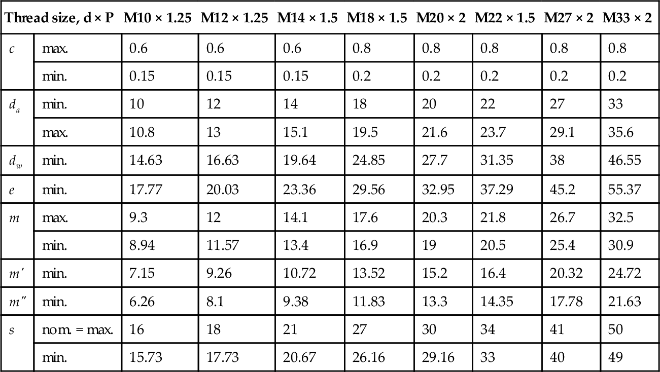
BS EN ISO 8673: 2001 Table 2 Non-preferred threads
| Thread size, d × P | M10 × 1.25 | M12 × 1.25 | M14 × 1.5 | M18 × 1.5 | M20 × 2 | M22 × 1.5 | M27 × 2 | M33 × 2 | M39 × 3 | M45 × 3 | M45 × 3 | M60 × 4 | |
| c | max. | 0.6 | 0.6 | 0.6 | 0.8 | 0.8 | 0.8 | 0.8 | 0.8 | 1 | 1 | 1 | 1 |
| min. | 0.15 | 0.15 | 0.15 | 0.2 | 0.2 | 0.2 | 0.2 | 0.2 | 0.3 | 0.3 | 0.3 | 0.3 | |
| da | min. | 10 | 12 | 14 | 18 | 20 | 22 | 27 | 33 | 39 | 45 | 52 | 60 |
| max. | 10.8 | 13 | 15.1 | 19.5 | 21.6 | 23.7 | 29.1 | 35.6 | 42.1 | 48.6 | 56.2 | 64.8 | |
| dw | min. | 14.63 | 16.63 | 19.64 | 24.85 | 27.7 | 31.35 | 38 | 46.55 | 55.86 | 64.7 | 74.2 | 83.41 |
| e | min. | 17.77 | 20.03 | 23.36 | 29.56 | 32.95 | 37.29 | 45.2 | 55.37 | 66.44 | 76.95 | 88.25 | 99.21 |
| m | max. | 8.4 | 10.8 | 12.8 | 15.8 | 18 | 19.4 | 23.8 | 28.7 | 33.4 | 36 | 42 | 48 |
| min. | 8.04 | 10.37 | 12.1 | 15.1 | 16.9 | 18.1 | 22.5 | 27.4 | 31.8 | 34.4 | 40.4 | 46.4 | |
| m′ | min. | 6.43 | 8.3 | 9.68 | 12.08 | 13.52 | 14.48 | 18 | 21.92 | 25.44 | 27.52 | 32.32 | 37.12 |
| m″ | min. | 5.63 | 7.26 | 8.47 | 10.57 | 11.83 | 12.67 | 15.75 | 19.18 | 22.26 | 24.08 | 28.28 | 32.48 |
| s | nom. = max. | 16 | 18 | 21 | 27 | 30 | 34 | 41 | 50 | 60 | 70 | 80 | 90 |
| min. | 15.73 | 17.73 | 20.67 | 26.16 | 29.16 | 33 | 40 | 49 | 58.8 | 68.1 | 78.1 | 87.8 | |

4.1.25 BS EN ISO 8674: 2001 Hexagon nuts style 2 with metric fine pitch threads - product grades A and B
Dimensions
Note: Symbols and descriptions of dimensions are specified in ISO 225.

BS EN ISO 8674: 2001 Table 1 Preferred threads
| Thread size, d × P | M8 × 1 | M10 × 1 | M12 × 1.5 | M16 × 1.5 | M20 × 1.5 | M24 × 2 | M30 × 2 | M36 × 3 | |
| c | max. | 0.6 | 0.6 | 0.6 | 0.8 | 0.8 | 0.8 | 0.8 | 0.8 |
| min. | 0.15 | 0.15 | 0.15 | 0.2 | 0.2 | 0.2 | 0.2 | 0.2 | |
| da | min. | 8 | 10 | 12 | 16 | 20 | 24 | 30 | 36 |
| max. | 8.75 | 10.8 | 13 | 17.3 | 21.6 | 25.9 | 32.4 | 38.9 | |
| dw | min. | 11.63 | 14.63 | 16.63 | 22.49 | 27.7 | 33.25 | 42.75 | 51.11 |
| e | min. | 14.38 | 17.77 | 20.03 | 26.75 | 32.95 | 39.55 | 50.85 | 60.79 |
| m | max. | 7.5 | 9.3 | 12 | 16.4 | 20.3 | 23.9 | 28.6 | 34.7 |
| min. | 7.14 | 8.94 | 11.57 | 15.7 | 19 | 22.6 | 27.3 | 33.1 | |
| m′ | min. | 5.71 | 7.15 | 9.26 | 12.56 | 15.2 | 18.08 | 21.84 | 26.48 |
| m″ | min. | 5 | 6.26 | 8.1 | 10.99 | 13.3 | 15.82 | 19.11 | 23.17 |
| s | nom. = max. | 13 | 16 | 18 | 24 | 30 | 36 | 46 | 55 |
| min. | 12.73 | 15.73 | 17.73 | 23.67 | 29.16 | 35 | 45 | 53.8 | |

BS EN ISO 8674: 2001 Table 2 Non − preferred threads
| Thread size, d × P | M10 × 1.25 | M12 × 1.25 | M14 × 1.5 | M18 × 1.5 | M20 × 2 | M22 × 1.5 | M27 × 2 | M33 × 2 | |
| c | max. | 0.6 | 0.6 | 0.6 | 0.8 | 0.8 | 0.8 | 0.8 | 0.8 |
| min. | 0.15 | 0.15 | 0.15 | 0.2 | 0.2 | 0.2 | 0.2 | 0.2 | |
| da | min. | 10 | 12 | 14 | 18 | 20 | 22 | 27 | 33 |
| max. | 10.8 | 13 | 15.1 | 19.5 | 21.6 | 23.7 | 29.1 | 35.6 | |
| dw | min. | 14.63 | 16.63 | 19.64 | 24.85 | 27.7 | 31.35 | 38 | 46.55 |
| e | min. | 17.77 | 20.03 | 23.36 | 29.56 | 32.95 | 37.29 | 45.2 | 55.37 |
| m | max. | 9.3 | 12 | 14.1 | 17.6 | 20.3 | 21.8 | 26.7 | 32.5 |
| min. | 8.94 | 11.57 | 13.4 | 16.9 | 19 | 20.5 | 25.4 | 30.9 | |
| m' | min. | 7.15 | 9.26 | 10.72 | 13.52 | 15.2 | 16.4 | 20.32 | 24.72 |
| m" | min. | 6.26 | 8.1 | 9.38 | 11.83 | 13.3 | 14.35 | 17.78 | 21.63 |
| s | nom. = max. | 16 | 18 | 21 | 27 | 30 | 34 | 41 | 50 |
| min. | 15.73 | 17.73 | 20.67 | 26.16 | 29.16 | 33 | 40 | 49 | |
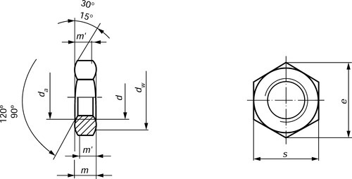
4.1.26 BS EN ISO 8675: 2001 Hexagon thin nuts with metric fine pitch threads - product grades A and B
Dimensions
Note: Symbols and descriptions of dimensions are specified in ISO 225.
BS EN ISO 8675: 2001 Table 1 Preferred threads
| Thread size, d × P | M × 1 | M10 × 1 | M12 × 1.5 | M16 × 1.5 | M20 × 1.5 | M24 × 2 | M30 × 2 | M36 × 3 | M42 × 3 | M48 × 3 | M56 × 4 | M64 × 4 | |
| da | min. | 8 | 10 | 12 | 16 | 20 | 24 | 30 | 36 | 42 | 48 | 56 | 64 |
| max. | 8.75 | 10.8 | 13 | 17.3 | 21.6 | 25.9 | 32.4 | 38.9 | 45.4 | 51.8 | 60.5 | 69.1 | |
| dw | min. | 11.63 | 14.63 | 16.63 | 22.49 | 27.7 | 33.25 | 42.75 | 51.11 | 59.95 | 69.45 | 78.66 | 88.16 |
| e | min. | 14.38 | 17.77 | 20.03 | 26.75 | 32.95 | 39.55 | 50.85 | 60.79 | 71.3 | 82.6 | 93.56 | 104.86 |
| m | max. | 4 | 5 | 6 | 8 | 10 | 12 | 15 | 18 | 21 | 24 | 28 | 32 |
| min. | 3.7 | 4.7 | 5.7 | 7.42 | 9.1 | 10.9 | 13.9 | 16.9 | 19.7 | 22.7 | 26.7 | 30.4 | |
| m' | min. | 2.96 | 3.76 | 4.56 | 5.94 | 7.28 | 8.72 | 11.12 | 13.52 | 15.76 | 18.16 | 21.36 | 24.32 |
| s | nom. = max. | 13 | 16 | 18 | 24 | 30 | 36 | 46 | 55 | 65 | 75 | 85 | 95 |
| min. | 12.73 | 15.73 | 17.73 | 23.67 | 29.16 | 35 | 45 | 53.8 | 63.1 | 73.1 | 82.8 | 92.8 | |

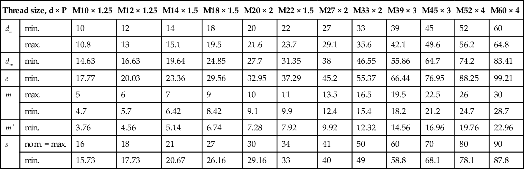
BS EN ISO 8675: 2001 Table 2 Non-preferred threads
| Thread size, d × P | M10 × 1.25 | M12 × 1.25 | M14 × 1.5 | M18 × 1.5 | M20 × 2 | M22 × 1.5 | M27 × 2 | M33 × 2 | M39 × 3 | M45 × 3 | M52 × 4 | M60 × 4 | |
| da | min. | 10 | 12 | 14 | 18 | 20 | 22 | 27 | 33 | 39 | 45 | 52 | 60 |
| max. | 10.8 | 13 | 15.1 | 19.5 | 21.6 | 23.7 | 29.1 | 35.6 | 42.1 | 48.6 | 56.2 | 64.8 | |
| dw | min. | 14.63 | 16.63 | 19.64 | 24.85 | 27.7 | 31.35 | 38 | 46.55 | 55.86 | 64.7 | 74.2 | 83.41 |
| e | min. | 17.77 | 20.03 | 23.36 | 29.56 | 32.95 | 37.29 | 45.2 | 55.37 | 66.44 | 76.95 | 88.25 | 99.21 |
| m | max. | 5 | 6 | 7 | 9 | 10 | 11 | 13.5 | 16.5 | 19.5 | 22.5 | 26 | 30 |
| min. | 4.7 | 5.7 | 6.42 | 8.42 | 9.1 | 9.9 | 12.4 | 15.4 | 18.2 | 21.2 | 24.7 | 28.7 | |
| m' | min. | 3.76 | 4.56 | 5.14 | 6.74 | 7.28 | 7.92 | 9.92 | 12.32 | 14.56 | 16.96 | 19.76 | 22.96 |
| s | nom. = max. | 16 | 18 | 21 | 27 | 30 | 34 | 41 | 50 | 60 | 70 | 80 | 90 |
| min. | 15.73 | 17.73 | 20.67 | 26.16 | 29.16 | 33 | 40 | 49 | 58.8 | 68.1 | 78.1 | 87.8 | |
4.1.27 BS 7764: 1994 Hexagon slotted nuts and castle nuts
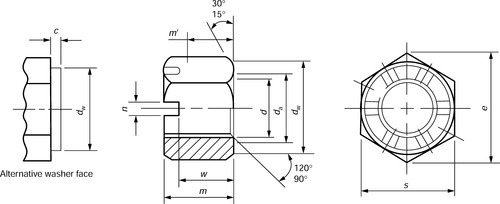

BS 7764: 1994 Table 1 Dimensions of hexagon slotted nuts and castle nuts
| d | M4 | M5 | M6 | M8 | M10 | M12 | (M14) | M16 | (M18) | M20 | (M22) | M24 | (M27) | M30 | (M33) | M36 | (M39) | M42 | (M45) | M48 | (M52) | M56 | (M60) | M64 | |
| p | 0 7 | 0.8 | 1 | 1.25 | 1.5 | 1.75 | 2 | 2 | 2.5 | 2 5 | 2.5 | 3 | 3 | 3.5 | 3.5 | 4 | 4 | 4.5 | 4.5 | 5 | 5 | 5.5 | 5.5 | 6 | |
| c | max | 0.4 | 0.5 | 0.5 | 0.6 | 0.6 | 0.6 | 0.6 | 0.8 | 0.8 | 08 | 0.8 | 0.8 | 0.8 | 0.8 | 0.8 | 0.8 | 1 | 1 | 1 | 1 | 1 | 1 | 1 | 1 |
| da | min. | 4 | 5 | 6 | 8 | 10 | 12 | 14 | 16 | 18 | 20 | 22 | 24 | 27 | 30 | 33 | 36 | 39 | 42 | 45 | 48 | 52 | 56 | 60 | 64 |
| max. | 4.6 | 5.75 | 6.75 | 8.75 | 10.8 | 13 | 15.1 | 17.3 | 19.5 | 21 6 | 23.7 | 25.9 | 29.1 | 32.4 | 35.6 | 38.9 | 42.1 | 45.4 | 48.6 | 51.8 | 56.2 | 60.5 | 64.8 | 69.1 | |
| de | max. | – | – | – | – | – | 16 | 19 | 22 | 25 | 28 | 30 | 34 | 38 | 42 | 46 | 50 | 55 | 58 | 62 | 65 | 70 | 75 | 80 | 85 |
| min. | – | – | – | – | – | 15.57 | 18.48 | 21.48 | 24.16 | 27.16 | 29.16 | 33 | 37 | 41 | 45 | 49 | 53.8 | 56.8 | 60.8 | 63.8 | 68.8 | 73.8 | 78.8 | 83.8 | |
| dw | min. | 5 9 | 6.9 | 8.9 | 11.6 | 14.6 | 16.6 | 19.6 | 22.5 | 24.8 | 277 | 31.4 | 33.2 | 38 | 42.7 | 46.6 | 51.1 | 55.9 | 59.9 | 64.7 | 69.4 | 74.2 | 78.7 | 83.4 | 88.2 |
| e | min. | 7 66 | 8.79 | 11.05 | 14.38 | 17.77 | 20.03 | 23.36 | 26.75 | 29.58 | 32.95 | 37.29 | 39.55 | 45.2 | 50.85 | 55.37 | 60.79 | 66.44 | 71.3 | 76.95 | 82.6 | 88.25 | 93.56 | 99.21 | 104.86 |
| m | max. | 5 | 6 | 7.5 | 9.5 | 12 | 15 | 16 | 19 | 21 | 22 | 26 | 27 | 30 | 33 | 35 | 38 | 40 | 46 | 48 | 50 | 54 | 57 | 63 | 66 |
| min. | 4.7 | 5.7 | 7.14 | 9.14 | 11.57 | 14.57 | 15.57 | 18.48 | 21.48 | 21.48 | 25.48 | 25.48 | 29.48 | 32.38 | 34.38 | 37.38 | 39.38 | 45.38 | 47.38 | 49.38 | 53.26 | 56.26 | 62.26 | 65.26 | |
| m’ | min. | 2 32 | 3.52 | 3.92 | 5.15 | 6.43 | 8.3 | 9.68 | 11.28 | 12.08 | 13.52 | 14.48 | 16.16 | 18 | 19.44 | 21.92 | 23.52 | 25.44 | 25.92 | 27.52 | 29.12 | 32.32 | 34.72 | 37.12 | 39.3 |
| n | min. | 1 2 | 1.4 | 2 | 2.5 | 2.8 | 3.5 | 3.5 | 4.5 | 4.5 | 4.5 | 5.5 | 5.5 | 5.5 | 7 | 7 | 7 | 7 | 9 | 9 | 9 | 9 | 9 | 11 | 11 |
| max. | 1 45 | 1.65 | 2.25 | 2.75 | 3.05 | 3.8 | 3.8 | 4.8 | 4.8 | 4.8 | 5.8 | 5.8 | 5.8 | 7.36 | 7.36 | 7.36 | 7.36 | 9.36 | 9.36 | 9.36 | 9.36 | 9.36 | 11.43 | 11.43 | |
| s | max. | 7 | 8 | 10 | 13 | 16 | 18 | 21 | 24 | 27 | 30 | 34 | 36 | 41 | 46 | 50 | 55 | 60 | 65 | 70 | 75 | 80 | 85 | 90 | 95 |
| min. | 6 78 | 7.78 | 9.78 | 12.73 | 15.73 | 17.73 | 20.67 | 23.67 | 26.16 | 29.16 | 33 | 35 | 40 | 45 | 49 | 53.8 | 58.8 | 63.1 | 68.1 | 73.1 | 78.1 | 82.8 | 87.8 | 92.8 | |
| w | max | 2.9 | 4 | 5 | 6.5 | 8 | 10 | 11 | 13 | 15 | 16 | 18 | 19 | 22 | 24 | 26 | 29 | 31 | 34 | 36 | 38 | 42 | 45 | 48 | 51 |
| min. | 3.2 | 3.7 | 4.7 | 6.14 | 7.64 | 9.64 | 10.57 | 12.59 | 14.57 | 15.57 | 17.57 | 18.48 | 21.48 | 23.48 | 25.48 | 28.48 | 30.38 | 33.38 | 35.38 | 37.38 | 41.38 | 44.38 | 47.38 | 50.26 | |
| For product grade A see Table 2 | For product grade B see Table 2 | ||||||||||||||||||||||||
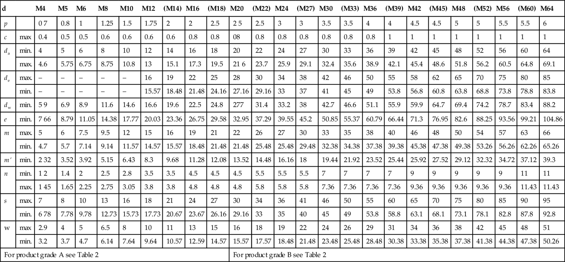
Notes: 1. Non − preferred sizes are shown in brackets.
2. Castle nuts shall not be specified below M12.
3. Castle nuts above M39 shall have eight slots.
BS 7764: 1994 Table 2
Characteristics of hexagon slotted nuts and castle nuts
| Characteristic | Requirement | ||
| Material | Steel | Stainless steel | Non-ferrous metal |
| Thread tolerance | Conforming to class 6H of BS 3643: Part 1: 1981 and BS 3643: Part 2: 1981 | ||
| Mechanical propertiesa | Conforming to material property class 6, 8 or 10 of BS EN 20898-2: 1992 | Conforming to material property class A2-70 of BS 6105: 1981 | Conforming to BS EN 28839: 1992 |
| Permissible dimensional deviations and deviations of form | Conforming to product grade A of BS 6322: Part 1: 1982 for thread sizes ≤s M16 Conforming to product grade B of BS 6322: Part 1: 1982 for thread sizes > M16 | ||
| Finish | As processed with a lubricant, unless otherwise agreed between the purchaser and supplierb,c | As processed, unless otherwise agreed between the purchaser and supplierc | As processed, unless otherwise agreed between the purchaser and supplierc |
| Acceptability | In accordance with BS 6587: 1985 | ||
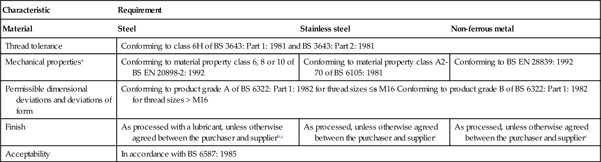
a Including the marking requirement.
b The lubricant shall contain a rust inhibitor unless otherwise agreed between the purchaser and supplier.
c Alternative surface finishes (e.g. electroplating) may be applied, if agreed between the purchaser and supplier.
4.1.28 BS EN ISO 898-1: 1999 Mechanical properties of fasteners: bolts, screw
Mechanical properties
When tested by the methods described in clause 8, the bolts, screws and studs shall, at room temperature, have the mechanical properties set out in BS EN ISO 898-1: 1999 Table 3.
BS EN ISO 898–1: 1999 Table 3
Mechanical properties of bolts, screws and studs
| Sub clause No. | Mechanical property | Property class | |||||||||||
| 3.6 | 4.6 | 4.8 | 5.6 | 5.8 | 6.8 | 8.8a | 9.8c | 10.9 | 12.9 | ||||
| d ≤ 16 mm | d > 16 mmb | ||||||||||||
| 5.1 and 5.2 | Tensile strength, Rmd,e, N/mm2 | nom. | 300 | 400 | 500 | 600 | 800 | 800 | 900 | 1 000 | 1 200 | ||
| min. | 330 | 400 | 420 | 500 | 520 | 600 | 800 | 830 | 900 | 1 040 | 1 220 | ||
| 5.3 | Vickers hardness, HV,F > 98 N | min. | 95 | 120 | 130 | 155 | 160 | 190 | 250 | 255 | 290 | 320 | 385 |
| max. | 250 | 320 | 335 | 360 | 380 | 435 | |||||||
| 5.4 | Brinell hardness, HB, F = 30D2 | min. | 90 | 114 | 124 | 147 | 152 | 181 | 238 | 242 | 276 | 304 | 366 |
| max. | 238 | 304 | 318 | 342 | 361 | 414 | |||||||
| HRB | 52 | 67 | 71 | 79 | 82 | 89 | − | − | − | − | − | ||
| 5.5 | Rockwell hardness, HR | HRC | − | − | − | − | − | − | 22 | 23 | 28 | 32 | 39 |
| HRB | 99.5 | − | − | − | − | − | |||||||
| HRC | − | 32 | 34 | 37 | 39 | 44 | |||||||
| 5.6 | Surface hardness, HV 0.3 | max. | − | − f | |||||||||
| 5.7 | Lower yield stress, ReLg, N/mm2 | nom. | 180 | 240 | 320 | 300 | 400 | 480 | − | − | − | − | − |
| min. | 190 | 240 | 340 | 300 | 420 | 480 | − | − | − | − | − | ||
| 5.8 | Proof stress, Rp0.2, N/mm2 | nom. | − | 640 | 640 | 720 | 900 | 1080 | |||||
| min. | − | 640 | 660 | 720 | 940 | 1100 | |||||||
| 5.9 | Stress under proofing load, 5p | Sp/ReL or Sp/Rp0 2 | 0.94 | 0.94 | 0.91 | 0.93 | 0.90 | 0.92 | 0.91 | 0.91 | 0.90 | 0.88 | 0.88 |
| N/mm2 | 180 | 225 | 310 | 280 | 380 | 440 | 580 | 600 | 650 | 830 | 970 | ||
| 5.10 | Elongation after fracture, A | min. | 25 | 22 | 14 | 20 | 10 | 8 | 12 | 12 | 10 | 9 | 8 |
| 5.11 | Strength under wedge loadinge | The values for full size bolts and screws (not studs) shall not be smaller than the minimum values for tensile strength shown in 5.2 | |||||||||||
| 5.12 | Impact strength, J | min. | − | 25 | 30 | 30 | 25 | 20 | 15 | ||||
| 5.13 | Head soundness | no fracture | |||||||||||
| 5.14 | Minimum height of non − decarburized thread zone, E | − | |||||||||||
| Maximum depth of complete decarburization, G | mm | − | 0.015 | ||||||||||

be tensile tested (e.g. due to head configuration).
a For bolts of property class 8.8 in diameters d 16 mm, there is an increased risk of nut stripping in the case of inadvertent over − tightening inducting a load in excess of proofing load. Reference to ISO 898.2 is recommended.
b For structural bolting the limit is 12 mm.
c Applies only to nominal thread diameters d 16 mm.
d Minimum tensile properties apply to products of nominal length I 2.5d. Minimum hardness applies to products of length I < 2.5d and other products which cannot
e For testing of full − size bolts, screws and studs, the loads given in BS EN ISO 898–1: 1999 Tables 6 to 9 (of the full standard) shall be applied.
f Surface hardness shall not be more than 30 Vickers points above the measured core hardness on the product when readings of both surface and core are carried out at HV 0.3. For property class 10.9, any increase in hardness at the surface which indicates that the surface hardness exceeds 390 HV is not acceptable.
g In cases where the lower yield stress ReL cannot be determined, it is permissible to measure the proof stress Rp0.2.
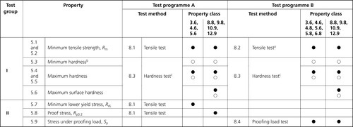
Mechanical properties to be determined
Two test programmes, A and B, for mechanical properties of bolts, screws and studs, using the methods described in clause 8, are set out in BSEN ISO 898-1: 1999 Table 5.
The application of programme B is always desirable, but is mandatory for products with breaking loads less than 500 kN. Programme A is suitable for machined test pieces and for bolts with a shank area less than the stress area.
BS EN ISO 898-1: 1999 Table 4
Key to test programmes (see BS EN ISO 898-1: 1999 Table 5)
| Size | Bolts and screws with thread diameter d 4 mm or length 1 < 2.5d a | Bolts and screws with thread diameter d > 4 mm and length 1 > 2.5d |
| Test decisive for acceptance |
a Also bolts and screws withspecial head or shank configurations which are weaker than the threaded
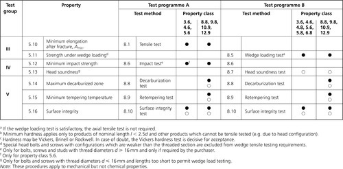
a If the wedge loading test is satisfactory, the axial tensile test is not required.
b Minimum hardness applies only to products of nominal length l 2.5d and other products which cannot be tensile tested (e.g. due to head configuration).
c Hardness may be Vickers, Brinell or Rockwell. In case of doubt, the Vickers hardness test is decisive for acceptance.
d Special head bolts and screws with configurations which are weaker than the threaded section are excluded from wedge tensile testing requirements.
e Only for bolts, screws and studs with thread diameters d 16 mm and only if required by the purchaser.
f Only for property class 5.6.
g Only for bolts and screws with thread diameters d 16 mm and lengths too short to permit wedge load testing.
Note: These procedures apply to mechanical but not chemical properties.
Minimum ultimate tensile loads and proofing loads

BS EN ISO 898-1: 1999 Table 7
Proofing loads ISO metric coarse pitch thread

aWhere no thread pitch is indicated in a thread designation, coarse pitch is specified. This is given in ISO 261 and ISO 262.
bFor structural bolting 50700, 68800 and 94500 N, respectively.

4.1.29 BS EN ISO 898-1: 1999 Marking
Symbols
Marking symbols are shown in BS EN ISO 898-1: 1999 Table 1.
Identification
Hexagon bolts and screws
Hexagon bolts and screws shall be marked with the designation symbol of the propertyclass described in clause 3.
The marking is obligatory for all property classes, preferably on the top of the head by indenting or embossing or on the side of the head by indenting (see Fig. 1).
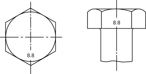
Marking is required for hexagon bolts and screws with nominal diameters d 5 mm where the shape of the product allows it, preferablyon the head.
Hexagon socket head cap screws
Hexagon socket head cap screws shall be marked with the designation symbol of the property class described in clause 3.
The marking is obligatory for property classes equal to or higher than 8.8, preferably on the side of the head by indenting or on the top of the head by indenting or embossing(see Fig. 2).
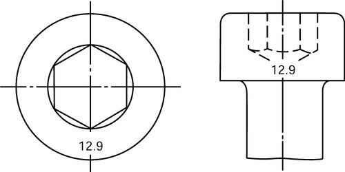
Marking is required for hexagon socket head cap screws with nominal diametersd 5 mm where the shape of the product allows it, preferably on the head.
The clock-face marking system asgiven for nuts in ISO 898-2 may be used as an alternative method on small hexagon socket head cap screws.
BS EN ISO 898-1: 1999 Table 1
Marking symbols
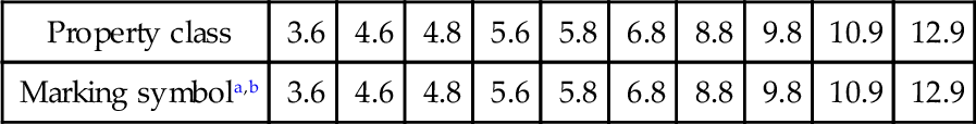
a The full-stop in the marking symbol may be omitted.
b When low carbon martensitic steels are used for property class 10.9 (see BS EN ISO 898-1: 1999 Table 2,the symbol 10.9 shall be underlined: 10.9.
Studs
Studs shall be marked with the designation symbol of the property class described in clause 3.
The marking is obligatory for property classes equal to or higher than 8.8, preferably on the extreme end of the threaded portion by indenting (see Fig. 3). For studs with interference fit, the marking shall be at the nut end.

Marking is required for studs with nominal diametersequal to or greater than 5 mm.
The symbols in BS EN ISO 898-1: 1999 Table 2 are permissible as an alternative identification method.
Other types of bolts and screws
The same marking system as described in the sections Hexagon bolts and screws, and Hexagon socket head cap screws shall be used for other types of bolts and screws of property classes 4.6,5.6 and all classes equal to or higher than 8.8, asdescribed in the appropriate International Standardsor, for special components, as agreed between the interested parties.
Marking of left-hand thread
Bolts and screws with left-hand thread shall be marked with the symbol shown in Fig 4, either on the top of the head or the point.
Marking is required for bolts and screws with nominal thread diameters 5 mm.
Alternative marking for left-hand thread may be used for hexagon bolts and screws asshown in Fig. 5.

Alternative marking
Alternative or optional permitted marking as stated in the sections Symbols, Identification and Marking of left-hand thread should be left to the choice of the manufacturer.
Trade (identification) marking
The trade (identification) marking of the manufacturer is mandatory on all products which are marked with property classes.
4.1.30 BS EN 20898-2: 1994 Mechanical properties of fasteners: nuts with specified proof load values - coarse thread


Proof load values
Proof load values are given in BS EN 20898-2: 1994 Table 2.
The nominal stress area Asis calculated as follows:
where:
d2 = basic pitch diameter of the external thread (see ISO 724);
d3 = minor diameter of the external thread;
d3
![]()
where:
d1 = basic pitch diameter of the external thread;
H = height of the fundamental triangle of the thread.
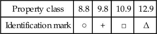
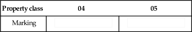
BS EN 20898-2: 1994 Table 3
Marking symbols for nuts with property classesin accordance with BS EN 20898-2 clause 3.1
| Property class | 4 | 5 | 6 | 8 | 9 | 10 | 12a or code symbol (clock-face system) | |
| Alternative marking | either designation symbol. | 4 | 5 | 6 | 8 | 9 | 10 | 12 |
| or code symbol (clock-face system) | 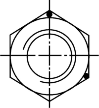 | 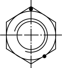 | 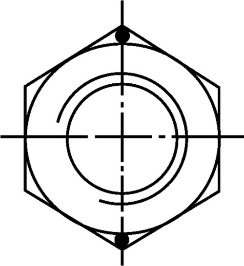 | 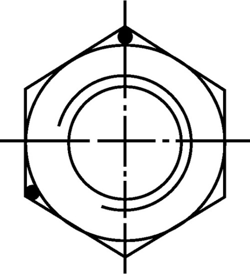 |  | 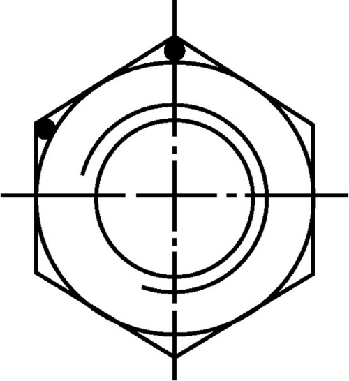 | 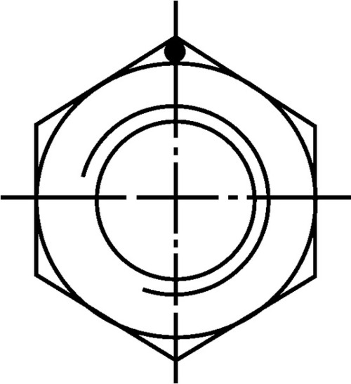 | |

a The marking dot cannot be replaced by the manufacturer–s mark.


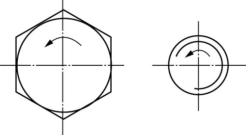
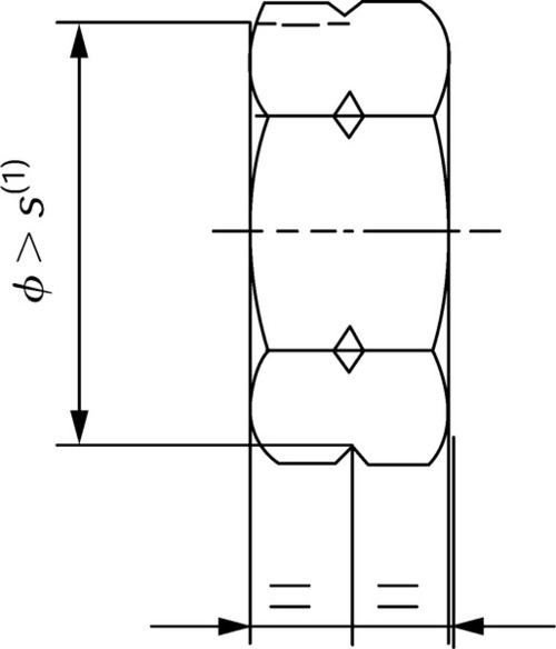
Marking of left-hand thread
Nuts with left-hand thread shall be marked as shown in Fig. 1 on one bearing surface of the nut by indenting.
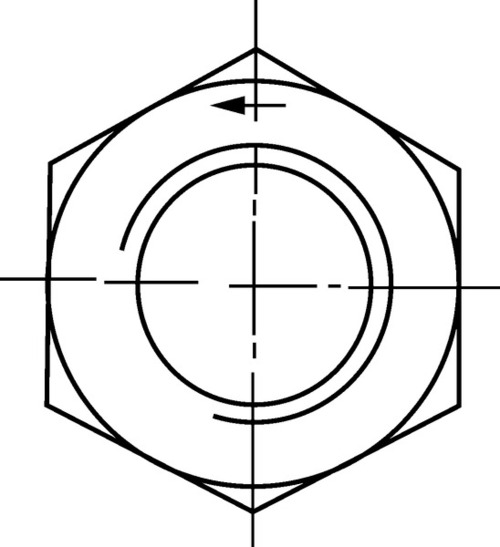
Marking is required for nuts with threads ≥ M5.
The alternative marking for left-hand thread shown in Fig. 2 may also be used.
Alternative marking
Alternative or optional permitted marking as stated in the sections Symbols, Identification and Marking of left-hand thread under Section 4.1.29 is left to the choice of the manufacturer.
Trade(identification) marking
The trade (identification) marking of the manufacturer is mandatory on all products covered by the obligatory marking requirementsfor property classes, provided this is possible for technical reasons. Packages, however, shall be marked in all cases.
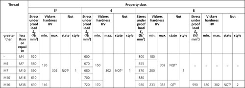
4.1.31 BS EN ISO 898-6: 1996 Mechanical properties of fasteners:nuts with specified proof load values - fine pitch thread
BS EN ISO 898-6: 1996 Table 1
Designation system for nuts with nominal heights ≥0.8d
| Property class of nut nut | Mating bolts | Nuts | ||
| Style 1 | Style 2 | |||
| Property class | Nominal thread diameter range (mm) | Nominal thread diameter range (mm) | ||
| 5 | 3.6, 4.6, 4.8 | d<39 | d<39 | - |
| 5.6, 5.8 | ||||
| 6 | 6.8 | d< 39 | d< 39 | - |
| 8 | 8.8 | d< 39 | d< 39 | d< 16 |
| 10 | 10.9 | d< 39 | d< 16 | d< 39 |
| 12 | 12.9 | d< 16 | - | d< 16 |

Note: In general, nuts of a higher property class can replace nuts of a lower property class. This is advisable for a bolt/nut assembly going into a stress higher than the yield stress or the stress under proof load ofthe bolt.
However, should tightening beyond bolt proof load take place, the net design is intended to ensure at least 10% of the over-tightened assemblies fail through bolt breakage in orderto warn the user that the installation practice isnot appropriate.
Note:For more detailed information on the strength of screw thread assemblies and for the styles of nuts, see ISO 898-2: 1992, Annex A.
Nuts with nominal heights ≥0.5d and < 0.8d (effective heights of thread ≥0.4d and < 0.6d)
Nuts with nominal heights ≥0.5d and < 0.8d (effective height of thread ≥0.4d and < 0.6d) are designated by a combination of two numbers: the secondindicates the nominal stress under proof load on ahardened test mandrel, while the first indicates that the load ability of a bolt-nut assembly is reduced in comparison with the loadability on a hardened test mandrel and also in comparison with a bolt-nut assembly described in Section 3.1. The effective loading capacity is not only determined by the hardness of the nut and the effective height of thread but also by the tensile strength of the botwith which the nut is assembled.BS EN ISO 898-6: 1996 Table 2 gives the designation system and the stresses under proof load of the nuts. Proof loads are shown in BS EN ISO 898-6: 1996 Table 3. A guide for minimum expected stripping strengths of the joints when these nuts are assembled with bolts ofvarious property classes is shown in BS EN ISO 898-6: 1996 Table 4.
BS EN ISO 898-6: 1996 Table 2
Designation system and stresses under proof load for nuts with nominal heights ≥0.5dand < 0.8d
| Property class of nut | Nominal stress under proof load (N/mm2) | Actual stress under proof load (N/mm2) |
| 04 | 400 | 380 |
| 05 | 500 | 500 |
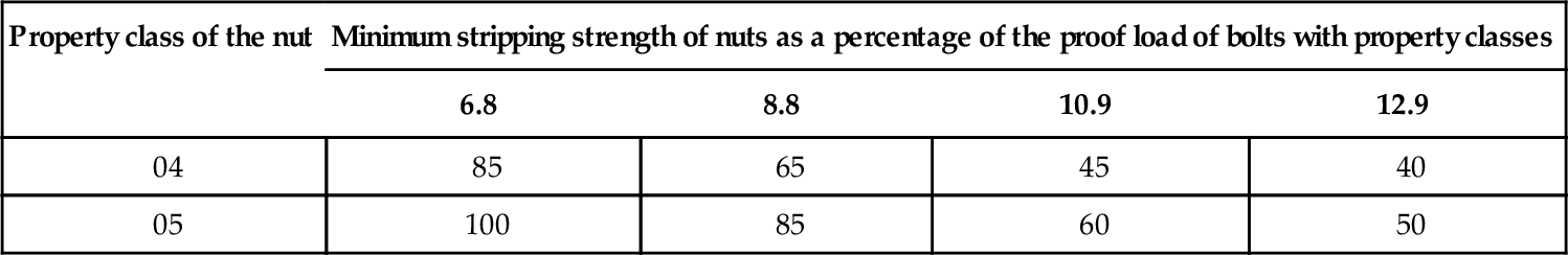
BS EN ISO 898-6: 1996 Table 4
Minimum stripping strength of nuts as a percentageof the proof load of bolts
| Property class of the nut | Minimum stripping strength of nuts as a percentage of the proof load of bolts with property classes | |||
| 6.8 | 8.8 | 10.9 | 12.9 | |
| 04 | 85 | 65 | 45 | 40 |
| 05 | 100 | 85 | 60 | 50 |
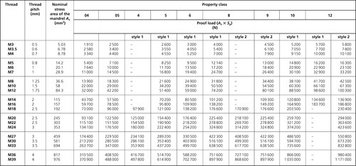
BS EN ISO 898–6: 1996 Table 3 Proof load valuesBS EN ISO 898–6: 1996 Table 3 Proof load values
| Thread size, d × P | Nominal stress area of mandrel As (mm2) | Property class | ||||||||
| 04 | 05 | 5 | 6 | 8 | 10 | 12 | ||||
| Proof load (As × Sp) (N) | ||||||||||
| style 1 | style 1 | style 1 | style 2 | style 1 | style 2 | style 2 | ||||
| M8 × 1 | 39.2 | 14 900 | 19 600 | 27 000 | 30 200 | 37 400 | 34900 | 43 100 | 41 400 | 47 000 |
| M10 × 1 | 64.5 | 24 500 | 32 200 | 44 500 | 49 700 | 61 600 | 57400 | 71 000 | 68 000 | 77 400 |
| M10 × 1.25 | 61.2 | 23 300 | 30 600 | 44 200 | 47 100 | 58 400 | 54 500 | 67 300 | 64 600 | 73 400 |
| M12 × 1.25 | 95.1 | 35 000 | 46 000 | 63 500 | 71 800 | 88 000 | 82 000 | 102 200 | 97 200 | 110 500 |
| M12 × 1.5 | 88.1 | 33 500 | 44 000 | 60 800 | 68 700 | 84 100 | 78 400 | 97 800 | 92 900 | 105 700 |
| M14 × 1.5 | 125 | 47 500 | 62 500 | 86 300 | 97 500 | 119 400 | 111 200 | 138 800 | 131 900 | 150 000 |
| M16 × 1.5 | 167 | 63 500 | 83 500 | 115 200 | 130 300 | 159 500 | 148 600 | 185 400 | 176 200 | 200 400 |
| M18 × 1.5 | 215 | 81 700 | 107 500 | 154 800 | 187 000 | 221 500 | – | – | 232 200 | – |
| M18 × 2 | 204 | 77 500 | 102 000 | 146 900 | 177 500 | 210 100 | – | – | 220 300 | – |
| M20 × 1.5 | 272 | 103 400 | 136 000 | 195 800 | 236 600 | 280 200 | – | – | 293 800 | – |
| M20 × 2 | 258 | 98 000 | 129 000 | 185 800 | 224 500 | 265 700 | – | – | 278 600 | – |
| M22 × 1.5 | 333 | 126 500 | 166 500 | 239 800 | 289 700 | 343 000 | – | – | 359 600 | – |
| M22 × 2 | 318 | 120 800 | 159 000 | 229 000 | 276 700 | 327 500 | – | – | 343 400 | – |
| M24 × 2 | 384 | 145 900 | 192 000 | 276 500 | 334 100 | 395 500 | – | – | 414 700 | – |
| M27 × 2 | 496 | 188 500 | 248 000 | 351 100 | 431 500 | 510 900 | – | – | 535 700 | – |
| M30 × 2 | 621 | 236 000 | 310 500 | 447 100 | 540 300 | 639 600 | – | – | 670 700 | – |
| M33 × 2 | 761 | 289 200 | 380 500 | 547 900 | 662 100 | 783 800 | – | – | 821 900 | – |
| M36 × 2 | 865 | 328 700 | 432 500 | 622 800 | 804 400 | 942 800 | – | – | 934 200 | – |
| M39 × 3 | 1030 | 391 400 | 515 000 | 741 600 | 957 900 | 1 123 000 | – | – | 1 112 000 | – |

Materials
Nuts of property classes 05, 8(style 1), 10 and 12 shall be hardened and tempered.
Nuts shall be made of steel conforming to the chemical composition limits specified in BS EN ISO 898-6: 1996 Table 5. The chemicalcomposition shall be analysed in accordance with relevant International Standards.
BS EN ISO 898-6: 1996 Table 5
Limits of chemical composition
| Property class | Chemical composition limits (check analysis), % | ||||
| C max. | Mn min. | P max. | S max. | ||
| 5a; 6 | - | 0.50 | - | 0.060 | 0.150 |
| 88b | 04a | 0.58 | 0.25 | 0.060 | 0.150 |
| 10b | 05b | 0.58 | 0.30 | 0.048 | 0.058 |
| 12b | - | 0.58 | 0.45 | 0.048 | 0.058 |

a Nuts of this property class may be manufactured from freecutting steel unless otherwise agreed between the purchaser and themanufacturer. In such cases, the following maximum sulphur, phosphorus and lead contents are permissible: Sulphur 0.34%; phosphorus 0.11%; lead 0.35%
b Alloying elements may beadded, if necessary to develop the mechanical properties of the nuts.
Mechanical properties
When tested by the methods described in clause 8, the nuts shall have the mechanical properties set out in BS EN ISO 898-6: 1996 Table 1under Section 4.1.30.
Proof load values
Proof load values are given in BS EN ISO 898-6: 1996 Table 3.
The nominal stress area As is calculated as follows:

where:
d2 = basic pitch diameter of the external thread (see ISO 724);
d3
![]()
d1 = basic minor diameter of the external thread;
H = height of the fundamental triangle of the thread.
4.1.32 BS EN 20898-7: 1995 Mechanical properties of fasteners: torsional testand minimum torques for bolts and screws with nominal diameters 1°10mm
BS EN 20898-7: 1995 Table 2 Minimum breaking torques
| Thread | Pitch (mm) | Minimum breaking torquea Mb min (N • m) | |||
| Property class | |||||
| 8.8 | 9.8 | 10.9 | 12.9 | ||
| M1 | 0.25 | 0.033 | 0.036 | 0.040 | 0.045 |
| M1.2 | 0.25 | 0.075 | 0.082 | 0.092 | 0.10 |
| M1.4 | 0.3 | 0.12 | 0.13 | 0.14 | 0.16 |
| M1.6 | 0.35 | 0.16 | 0.18 | 0.20 | 0.22 |
| M2 | 0.4 | 0.37 | 0.40 | 0.45 | 0.50 |
| M2.5 | 0.45 | 0.82 | 0.90 | 1.0 | 1.1 |
| M3 | 0.5 | 1.5 | 1.7 | 1.9 | 2.1 |
| M3.5 | 0.6 | 2.4 | 2.7 | 3.0 | 3.3 |
| M4 | 0.7 | 3.6 | 3.9 | 4.4 | 4.9 |
| M5 | 0.8 | 7.6 | 8.3 | 9.3 | 10 |
| M6 | 1 | 13 | 14 | 16 | 17 |
| M7 | 1 | 23 | 25 | 28 | 31 |
| M8 | 1.25 | 33 | 36 | 40 | 44 |
| M8 × 1 | – | 38 | 42 | 46 | 52 |
| M10 | 1.5 | 66 | 72 | 81 | 90 |
| M10 × 1 | – | 84 | 92 | 102 | 114 |
| M10 × 1.25 | – | 75 | 82 | 91 | 102 |

a These minimum breaking torques are valid for bolts and screws with the thread tolerances 6g, 6f and 6e.
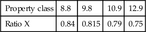
4.1.33 BS EN ISO 4762: 2004 Metric hexagon socket head screws
ISO 10683, Fasteners - Non-electrolytically applied zinc flake coatings.
ISO 23429, Gauging of hexagon sockets.
See Fig. 1 and BS EN ISO 4762: 2004 Table 1.
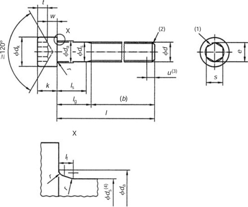

Figure 1

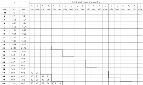
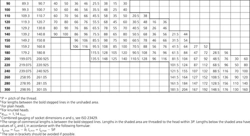


Dimensions
Note: Symbols and designations of dimensions are defined in ISO 225.
For broached sockets which are at the maximum limit of size the overcut resulting from drilling shall not exceed 1/3 of the length of any flat of the socket which is e/2.
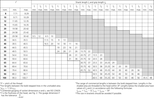
4.1.34 BS EN ISO 10642: 2004 Hexagon socket countersunk head screws
Dimensions and gauging of head
See Figs 1 and 2, and BS EN ISO 10642: 2004 Table 1.
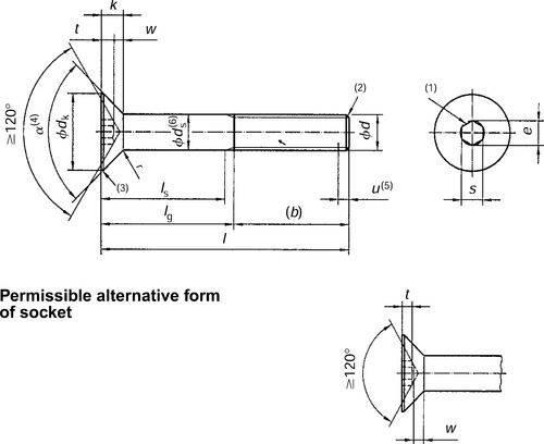
(1) A slight rounding or countersink at the mouth of the socket is permissible.
(2) Point to be chamfered or for sizes M4 and below 'as rolled' in accordance to ISO 4753.
(3) Edge of the head to be truncated or rounded.
(4) α = 90°-92°
(5) Incomplete thread u ≤ 2
(6) ds applies if values of ls,min are specified.

Dimensions
Note: Symbols and designations of dimensions are defined in ISO 225.
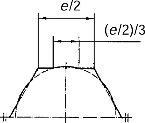
For broached sockets which are at the maximum limit of size the overcut resulting from drilling shall not exceed 1/3 of the length of any flat of the socket which is e/2.
Gauging of head
The top surface of the screw shall be located between the gauge surfaces A and B.
Requirements and reference International Standards
See BS EN ISO 10642: 2004 Tables 2 and 3.
BS EN ISO 10642: 2004 Table 2
Requirements and reference International Standards
| Material | Steel | |
| General requirements | International Standard | ISO 8992 |
| Thread | Tolerance | 6g for property classes 8.8 and 10.9; 5g6g for property class 12.9 |
| International Standards | ISO 261, ISO 965-2, ISO 965-3 | |
| Mechanical | Property classa | 8.8, 10.9, 12.9 |
| properties | International Standard | ISO 898-1 |
| Tolerances | Product grade | A |
| International Standard | ISO 4759-1 | |
| Finish | As processed Requirements for electroplating are covered in ISO 4042 Requirements for non-electrolytically applied zinc flake coatings are covered in ISO 10683 | |
| Surface discontinuities | Limits for surface discontinuities are given in ISO 6157-1 and ISO 6157-3 for property class 12.9 | |
| Acceptability | Acceptance procedure is covered in ISO 3269 | |

a Because of their head configurations, these screws may not meet the minimum ultimate tensile load for property classes 8.8, 10.9 and 12.9, specified in ISO 898-1, when tested in accordance with test programme B. They shall nevertheless meet the other material and property requirements for property classes 8.8, 10.9 and 12.9 specified in ISO 898-1. In addition, when full-size screws are loaded with the head supported on a suitable collar (conical bearing surface) using the type of testing fixture illustrated in ISO 898-1, they shall withstand, without fracture, the minimum ultimate tensile loads given in BS EN ISO 10642: 2004 Table 3. If tested to failure, the fracture may occur in the threaded section, the head, the shank or at the head/shank junction.
BS EN ISO 10642: 2004 Table 3
Minimum ultimate tensile loads for hexagon socket countersunk head screws
| Thread size, d | Property class | ||
| 8.8 | 10.9 | 12.9 | |
| Minimum ultimate tensile load (N) | |||
| M3 | 3220 | 4180 | 4190 |
| M4 | 5 620 | 7 300 | 8 560 |
| M5 | 9080 | 11 800 | 13 800 |
| M6 | 12 900 | 16700 | 19 600 |
| M8 | 23 400 | 30 500 | 35 700 |
| M10 | 37100 | 48 200 | 56600 |
| M12 | 53 900 | 70200 | 82 400 |
| M14 | 73 600 | 96 000 | 112 000 |
| M16 | 100000 | 130000 | 154000 |
| M20 | 162000 | 204000 | 239000 |

Eighty per cent of the values specified in ISO 898-1
Designation
Example.
A hexagon socket countersunk head screw with thread M12 nominal length l = 40 mm and property class 12.9 is designated as follows:
Hexagon socket countersunk head screw ISO 10642-M12 × 40-12.9
For information concerning hexagon socket countersunk head screws in inch dimensions see BS2470.
4.1.35 BS4827 ISO metric screw threads, miniature series

Dimensions in mm
| Nominal size | Pitch of thread P | Majordiameter | Pitch (effective) diameter | Minor diameter | |
| 1st choice | 2nd choice | ||||
| S-0.3 | 0.080 | 0.300000 | 0.248038 | 0.223200 | |
| S-0.35 | 0.090 | 0.350000 | 0.291 543 | 0.263600 | |
| S-0.4 | 0.100 | 0.400000 | 0.335048 | 0.304000 | |
| S-0.45 | 0.100 | 0.450000 | 0.385048 | 0.354000 | |
| S-0.5 | 0.125 | 0.500000 | 0.418810 | 0.380000 | |
| S-0.55 | 0.125 | 0.550 000 | 0.468810 | 0.430000 | |
| S-0.6 | 0.150 | 0.600 000 | 0.502 572 | 0.456000 | |
| S-0.7 | 0.175 | 0.700000 | 0.586334 | 0.532 000 | |
| S-0.8 | 0.200 | 0.800000 | 0.670096 | 0.608000 | |
| S-0.9 | 0.225 | 0.900000 | 0.753858 | 0.684000 | |
| S-1 | 0.250 | 1.000 000 | 0.837620 | 0.760000 | |
| S-1.1 | 0.250 | 1.100 000 | 0.937620 | 0.860000 | |
| S-1.2 | 0.250 | 1.200 000 | 1.037 620 | 0.960000 | |
| S-1.4 | 0.300 | 1.400 000 | 1.205144 | 1.112 000 | |
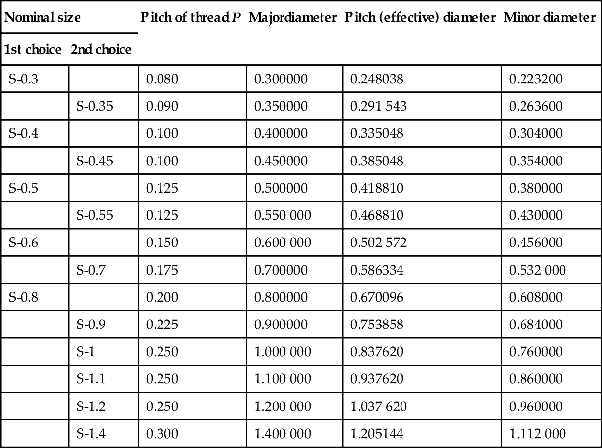
For full range and further information see BS 4827.
4.1.36 BS3643-1/2 ISO metric screw threads: constantpitchseries
Dimensions in mm
4.1.36 BS3643 − 1/2 ISO metric screw threads: constant pitch series
| Pitch of thread | Basic major diameter | Pitch (effective) diameter | Basic minor diameter | |||
| 1st choice | 2nd choice | 3rd choice | External | Internal | ||
| 0.25 | 2.0 | − | − | 1.84 | 1.69 | 1.73 |
| 0.25 | − | 2.2 | − | 2.04 | 1.89 | 1.93 |
| 0.35 | 2.5 | − | − | 2.27 | 2.07 | 2.12 |
| 0.35 | 3.0 | − | − | 2.77 | 2.57 | 2.62 |
| 0.35 | − | 3.5 | − | 3.27 | 3.07 | 3.12 |
| 0.50 | 4.0 | − | − | 3.68 | 3.39 | 3.46 |
| 0.50 | − | 4.5 | − | 4.18 | 3.86 | 3.96 |
| 0.50 | 5.0 | − | − | 4.68 | 4.39 | 4.46 |
| 0.50 | − | − | 5.5 | 5.18 | 4.86 | 4.96 |
| 0.75 | 6.0 | − | − | 5.51 | 5.08 | 5.19 |
| 0.75 | − | − | 7.0 | 6.51 | 6.08 | 6.19 |
| 0.75 | 8.0 | − | − | 7.51 | 7.08 | 7.19 |
| 0.75 | − | − | 9.0 | 8.51 | 8.08 | 8.19 |
| 0.75 | 10.0 | − | − | 9.51 | 9.08 | 9.19 |
| 0.75 | − | − | 11.0 | 10.51 | 10.08 | 10.19 |
| 1.0 | 8.0 | − | − | 7.35 | 6.77 | 6.92 |
| 1.0 | − | − | 9.0 | 8.35 | 7.77 | 7.92 |
| 1.0 | 10.0 | − | − | 9.35 | 8.77 | 8.92 |
| 1.0 | − | − | 11.0 | 10.35 | 9.77 | 9.92 |
| 1.0 | 12.0 | − | − | 11.35 | 10.77 | 10.92 |
| 1.0 | − | 14.0 | − | 13.35 | 12.77 | 12.92 |
| 1.0 | − | − | 15.0 | 14.35 | 13.77 | 13.92 |
| 1.0 | 16.0 | − | − | 15.35 | 14.77 | 14.92 |
| 1.0 | − | − | 17.0 | 16.35 | 15.77 | 15.92 |
| 1.0 | − | 18.0 | − | 17.35 | 16.77 | 16.92 |
| 1.0 | 20.0 | − | − | 19.35 | 18.77 | 18.92 |
| 1.0 | − | 22.0 | − | 21.35 | 21.77 | 21.92 |
| 1.0 | 24.0 | − | − | 23.35 | 22.77 | 22.92 |
| 1.0 | − | − | 25.0 | 24.35 | 23.77 | 23.92 |
| 1.0 | − | 27.0 | − | 26.35 | 25.77 | 25.92 |
| 1.0 | − | − | 28.0 | 27.35 | 26.77 | 26.92 |
| 1.0 | 30.0 | − | − | 29.35 | 28.77 | 28.92 |
| 1.25 | 10.0 | − | − | 9.19 | 8.47 | 8.65 |
| 1.25 | 12.0 | − | − | 11.19 | 10.47 | 10.65 |
| 1.25a | − | 14.0a | − | 13.19 | 12.47 | 12.65 |
| 1.5 | 12.0 | − | − | 11.03 | 10.16 | 10.38 |
| 1.5 | − | 14.0 | − | 13.03 | 12.16 | 12.38 |
| 1.5 | − | − | 15.0 | 14.03 | 13.16 | 13.38 |
| 1.5 | 16.0 | − | − | 15.03 | 14.16 | 14.38 |
| 1.5 | − | − | 17.0 | 16.03 | 15.16 | 15.38 |
| 1.5 | − | 18.0 | − | 17.03 | 16.16 | 16.38 |
| 1.5 | 20.0 | − | − | 19.03 | 18.16 | 18.38 |
| 1.5 | − | 22.0 | − | 21.03 | 20.16 | 20.38 |
| 1.5 | 24.0 | − | − | 23.03 | 22.16 | 22.38 |
| 1.5 | − | − | 25.0 | 24.03 | 23.16 | 23.38 |
| 1.5 | − | − | 26.0 | 25.03 | 24.16 | 24.38 |
| 1.5 | − | 27.0 | − | 26.03 | 25.16 | 25.38 |
| 1.5 | − | − | 28.0 | 27.03 | 26.16 | 26.38 |
| 1.5 | 30.0 | − | − | 29.03 | 28.16 | 28.38 |
| 1.5 | − | − | 32.0 | 31.03 | 30.16 | 30.38 |
| 1.5 | − | 33.0 | − | 32.03 | 31.16 | 31.38 |
| 1.5 | − | − | 35.0 | 34.03 | 33.16 | 33.38 |
| The 1.5 mm pitch series continues to a maximum diameter of 80 mm | ||||||
| 2.0 | − | 18.0 | − | 16.70 | 15.55 | 15.84 |
| 2.0 | 20.0 | − | − | 18.70 | 17.55 | 17.84 |
| 2.0 | − | 22.0 | − | 20.70 | 19.55 | 19.84 |
| 2.0 | 24.0 | − | − | 22.70 | 21.55 | 21.84 |
| 2.0 | − | − | 25.0 | 23.70 | 22.55 | 22.84 |
| 2.0 | − | − | 26.0 | 24.70 | 23.55 | 23.84 |
| 2.0 | − | 27.0 | − | 25.70 | 24.55 | 24.84 |
| 2.0 | − | − | 28.0 | 26.70 | 25.55 | 25.84 |
| 2.0 | 30.0 | − | − | 28.70 | 27.55 | 27.84 |
| 2.0 | − | − | 32.0 | 30.70 | 29.55 | 29.84 |
| 2.0 | − | 33.0 | − | 31.70 | 30.55 | 30.84 |
| 2.0 | − | − | 35.0 | 33.70 | 32.55 | 32.84 |
| The 2.0 mm pitch series continues to a maximum diameter of 150 mm | ||||||
| 3.0 | 30.0 | − | − | 28.05 | 26.32 | 26.75 |
| 3.0 | − | 33.0 | − | 31.05 | 29.32 | 29.75 |
| 3.0 | 36.0 | − | − | 34.05 | 32.32 | 32.75 |
| 3.0 | − | − | 38.0 | 36.05 | 34.32 | 34.75 |
| 3.0 | − | 39.0 | − | 37.05 | 35.32 | 35.75 |
| 3.0 | − | − | 40.0 | 38.05 | 36.32 | 36.75 |
| 3.0 | 42.0 | − | − | 40.05 | 38.32 | 38.75 |
| 3.0 | − | 45.0 | − | 43.05 | 41.32 | 41.75 |
| 3.0 | 48.0 | − | − | 46.05 | 44.32 | 44.75 |
| 3.0 | − | − | 50.0 | 48.05 | 46.32 | 46.75 |
| 3.0 | − | 52.0 | − | 50.05 | 48.32 | 48.75 |
| 3.0 | − | − | 55.0 | 53.05 | 51.32 | 51.75 |
| The 3.0 mm pitch series continues to a maximum diameter of 250 mm | ||||||
| 4.0 | 42.0 | − | − | 39.40 | 37.09 | 37.67 |
| 4.0 | − | 45.0 | − | 42.40 | 40.09 | 40.67 |
| 4.0 | 48.0 | − | − | 45.40 | 43.09 | 43.67 |
| 4.0 | − | − | 50.0 | 47.40 | 45.09 | 45.67 |
| 4.0 | − | 52.0 | − | 49.40 | 47.09 | 47.67 |
| 4.0 | − | − | 55.0 | 52.40 | 50.09 | 50.67 |
| 4.0 | 56.0 | − | − | 53.40 | 51.09 | 51.67 |
| 4.0 | − | − | 58.0 | 55.40 | 53.09 | 53.67 |
| 4.0 | − | 60.0 | − | 57.40 | 55.09 | 55.67 |
| 4.0 | − | − | 62.0 | 59.40 | 57.09 | 57.67 |
| 4.0 | 64.0 | − | − | 61.40 | 59.09 | 59.67 |
| 4.0 | − | − | 65.0 | 62.40 | 60.09 | 60.67 |
| The 4.0 mm pitch series continues to a maximum diameter of 300 mm | ||||||
| 6.0 | − | − | 70.0 | 66.10 | 62.64 | 63.50 |
| 6.0 | 72.0 | − | − | 68.10 | 64.64 | 65.50 |
| 6.0 | − | 76.0 | − | 72.10 | 68.64 | 69.50 |
| 6.0 | 80.0 | − | − | 76.10 | 72.64 | 73.50 |
| 6.0 | − | 85.0 | − | 81.10 | 77.64 | 78.50 |
| 6.0 | 90.0 | − | − | 86.10 | 82.64 | 83.50 |
| 6.0 | − | 95.0 | − | 91.10 | 87.64 | 88.50 |
| 6.0 | 100.0 | − | − | 96.10 | 92.64 | 93.50 |
| 6.0 | − | 105.0 | − | 101.10 | 97.64 | 98.50 |
| 6.0 | 110.0 | − | − | 106.10 | 102.64 | 103.50 |
| 6.0 | − | 115.0 | − | 111.10 | 107.64 | 108.50 |
| 6.0 | − | 120.0 | − | 116.10 | 112.64 | 113.50 |
| 6.0 | 125.0 | − | − | 121.10 | 117.64 | 118.50 |
| The 6.0 mm pitch series continues to a maximum diameter of 300 mm s | ||||||
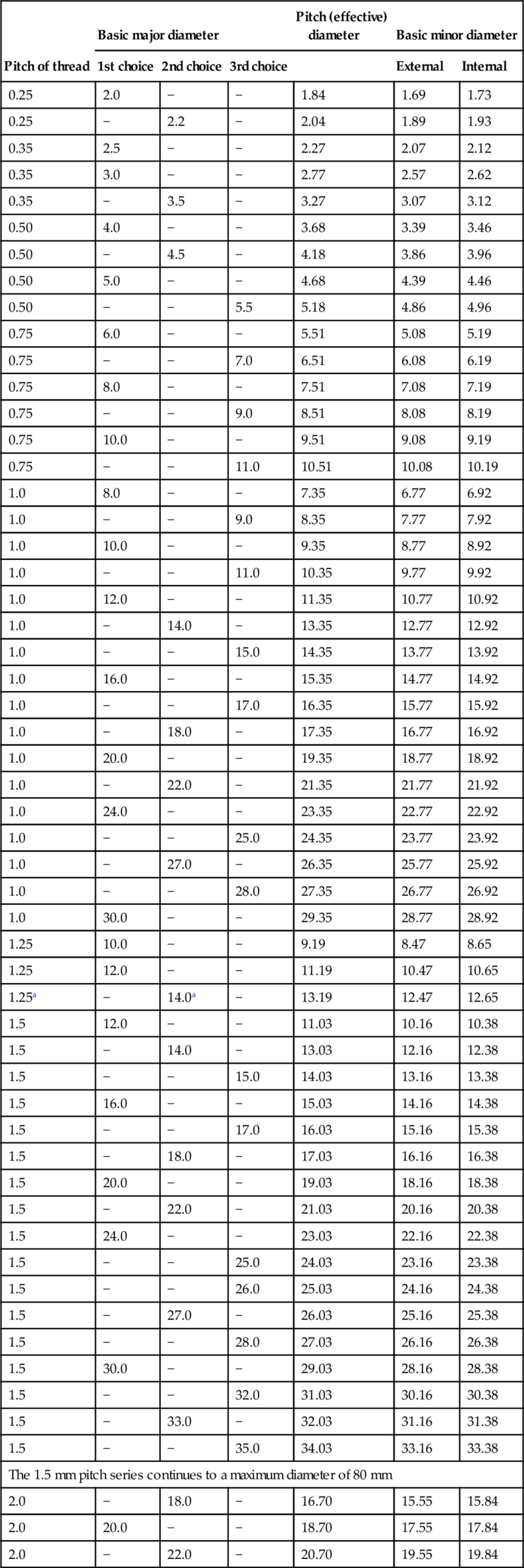

For further information see BS 3643.
a This size sparking plugs only
4.1.37 BS EN ISO 228-1: 2003 Pipe threads where pressure-tight joints are not made on the threads
Part 1: Dimensions, tolerances and designation
Scope
This part of ISO 228 specifies the requirements for thread form, dimensions, tolerances and designation for fastening pipe threads, thread sizes 1/16 to 6 inclusive. Both internal and external threads are parallel threads, intended for the mechanical assembly of the component parts of fittings, cocks and valves, accessories, etc.
These threads are not suitable as jointing threads where a pressure-tight joint is made on the thread. If assemblies with such threads must be made pressure-tight, this should be effected by compressing two tightening surfaces outside the threads, and by interposing and appropriate seal.
Notes:
• For pipe threads where pressure-tight joints are made on the threads, see ISO 7-1.
• ISO 228-2 gives details of methods for verification of fastening thread dimensions and form, and recommended gauging systems.
Normative reference
The following normative document contains provisions which, through reference in this text, constitute provisions of this part of ISO 228. For dated references, subsequent amendments to, or revisions of, any of these publications do not apply. However, parties to agreements based on this part of ISO 228 are encouraged to investigate the possibility of applying the most recent editions of the normative document indicated below. For undated references, the latest edition of the normative document referred to applies. Members of ISO and IEC maintain registers of currently valid International Standards.
ISO 7-1:1994, Pipe threads where pressure-tight joints are made on the threads - Part 1: Dimensions, tolerances and designation.
Symbols
For the purposes of this part of ISO 228, the following symbols apply:
A Tighter class of tolerance of external pipe threads where pressure-tight joints are not made on the threads.
B Wider class of tolerance of external pipe threads where pressure-tight joints are not made on the threads.
D =d; major diameter of the internal thread.
D1 = D - 1,280 654 P=d1; minor diameter of the internal thread.
D1 = D - 0,640 327 P=d2; pitch diameter of the internal thread.
d Major diameter of the external thread.
d1 = d -1,280 654 P;minor diameter of the external thread.
d2 = d - 0,640 327 P; pitch diameter of the external thread.
G Pipe thread where pressure-tight joints are not made on the threads.
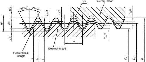
H Height of the fundamental triangle of the thread.
h Height of the thread profile with rounded crests and roots.
P Pitch.
r Radius of rounded crests and roots.
TD1 Tolerance on the minor diameter of the internal thread.
TD2 Tolerance on the pitch diameter of the internal thread.
Td Tolerance on the major diameter of the external thread.
Td2 Tolerance on the pitch diameter of the external thread.
Dimensions
The profile of these threads is identical with that of the parallel thread specified in ISO 7-1. The internal and external threads covered by this part of ISO 228 are both parallel.
Unless otherwise specified, the thread in accordance with this part of ISO 228 is a right- hand thread. (See also clause 5.)
Threads are normally of the truncated form, with crests truncated to the limits of tolerance as given in columns 14 and 15 of BS EN ISO 228-1: 2003 Table 1. The exception to this is on internal threads, where they are likely to be assembled with external threads in accordance with ISO 7-1, and in which case the thread length shall be equal to or greater than that specified in ISO 7-1.
BS EN ISO 228-1: 2003 Table 1
Thread dimensions
| Designation of thread | Number of threads in 25.4mm | Pitch P | Height of thread h | Diameters | Tolerance on pitch diametera | Tolerance on minor diameter | Tolerance on major diameter | ||||||||
| Internal thread TD2 | External thread Td2 | Internal thread TD1 | External thread Td | ||||||||||||
| major d = D | pitch d2 = D2 | minor d1 = D1 | Lower deviation | Upper deviation | Lower deviation Class A | Lower deviation Class B | Upper deviation | Lower deviation | Upper deviation | Lower deviation | Upper deviation | ||||
| 1 | 2 | 3 | 4 | 5 | 6 | 7 | 8 | 9 | 10 | 11 | 12 | 13 | 14 | 15 | 16 |
| 1/16 | 28 | 0.907 | 0.581 | 7.723 | 7.142 | 6.561 | 0 | + 0.107 | -0.107 | -0.214 | 0 | 0 | + 0.282 | -0.214 | 0 |
| 1/8 | 28 | 0.907 | 0.581 | 9.728 | 9.147 | 8.566 | 0 | + 0.107 | -0.107 | -0.214 | 0 | 0 | +0.282 | -0.214 | 0 |
| 1/4 | 19 | 1.337 | 0.856 | 13.157 | 12.301 | 11.445 | 0 | + 0.125 | -0.125 | -0.250 | 0 | 0 | + 0.445 | -0.250 | 0 |
| 3/8 | 19 | 1.337 | 0.856 | 16.662 | 15.806 | 14.950 | 0 | + 0.125 | -0.125 | -0.250 | 0 | 0 | + 0.445 | -0.250 | 0 |
| 1/2 | 14 | 1.814 | 1.162 | 20.955 | 19.793 | 18.631 | 0 | + 0.142 | -0.142 | -0.284 | 0 | 0 | +0.541 | -0.284 | 0 |
| 5/8 | 14 | 1.814 | 1.162 | 22.911 | 21.749 | 20.587 | 0 | + 0.142 | -0.142 | -0.284 | 0 | 0 | +0.541 | -0.284 | 0 |
| 3/4 | 14 | 1.814 | 1.162 | 26.441 | 25.279 | 24.117 | 0 | +0.142 | -0.142 | -0.284 | 0 | 0 | + 0.541 | -0.284 | 0 |
| 7/8 | 14 | 1.814 | 1.162 | 30.201 | 29.039 | 27.877 | 0 | + 0.142 | -0.142 | -0.284 | 0 | 0 | + 0.541 | -0.284 | 0 |
| 1 | 11 | 2.309 | 1.479 | 33.249 | 31.770 | 30.291 | 0 | +0.180 | -0.180 | -0.360 | 0 | 0 | + 0.640 | -0.360 | 0 |
| 1 1/8 | 11 | 2.309 | 1.479 | 37.897 | 36.418 | 34.939 | 0 | +0.180 | -0.180 | -0.360 | 0 | 0 | + 0.640 | -0.360 | 0 |
| 1 1/4 | 11 | 2.309 | 1.479 | 41.910 | 40.431 | 38.952 | 0 | +0.180 | -0.180 | -0.360 | 0 | 0 | + 0.640 | -0.360 | 0 |
| 1 1/2 | 11 | 2.309 | 1.479 | 47.803 | 46.324 | 44.845 | 0 | +0.180 | -0.180 | - 0.360 | 0 | 0 | + 0.640 | -0.360 | 0 |
| 1 3/4 | 11 | 2.309 | 1.479 | 53.746 | 52.267 | 50.788 | 0 | +0.180 | -0.180 | - 0.360 | 0 | 0 | + 0.640 | -0.360 | 0 |
| 2 | 11 | 2.309 | 1.479 | 59.614 | 58.135 | 56.656 | 0 | +0.180 | -0.180 | - 0.360 | 0 | 0 | + 0.640 | -0.360 | 0 |
| 2 1/4 | 11 | 2.309 | 1.479 | 65.710 | 64.231 | 62.752 | 0 | +0.217 | -0.217 | -0.434 | 0 | 0 | +0.640 | -0.434 | 0 |
| 2 1/2 | 11 | 2.309 | 1.479 | 75.184 | 73.705 | 72.226 | 0 | +0.217 | -0.217 | -0.434 | 0 | 0 | +0.640 | -0.434 | 0 |
| 2 3/4 | 11 | 2.309 | 1.479 | 81.534 | 80.055 | 78.576 | 0 | +0.217 | -0.217 | -0.434 | 0 | 0 | +0.640 | -0.434 | 0 |
| 3 | 11 | 2.309 | 1.479 | 87.884 | 86.405 | 84.926 | 0 | +0.217 | -0.217 | -0.434 | 0 | 0 | +0.640 | -0.434 | 0 |
| 3 1/2 | 11 | 2.309 | 1.479 | 100.330 | 98.851 | 97.372 | 0 | +0.217 | -0.217 | -0.434 | 0 | 0 | +0.640 | -0.434 | 0 |
| 4 | 11 | 2.309 | 1.479 | 113.030 | 111.551 | 110.072 | 0 | +0.217 | -0.217 | -0.434 | 0 | 0 | +0.640 | -0.434 | 0 |
| 4 1/2 | 11 | 2.309 | 1.479 | 125.730 | 124.251 | 122.772 | 0 | +0.217 | -0.217 | -0.434 | 0 | 0 | +0.640 | -0.434 | 0 |
| 5 | 11 | 2.309 | 1.479 | 138.430 | 139.951 | 135.472 | 0 | +0.217 | -0.217 | -0.434 | 0 | 0 | +0.640 | -0.434 | 0 |
| 5 1/2 | 11 | 2.309 | 1.479 | 151.130 | 149.651 | 148.172 | 0 | +0.217 | -0.217 | -0.434 | 0 | 0 | +0.640 | -0.434 | 0 |
| 6 | 11 | 2.309 | 1.479 | 163.830 | 162.351 | 160.872 | 0 | + 0.217 | -0.217 | -0.434 | 0 | 0 | + 0.640 | -0.434 | 0 |
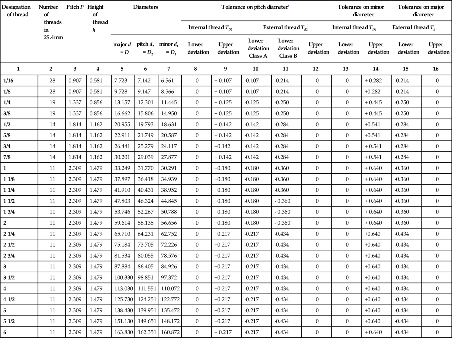
a For thin-walled parts, the tolerances apply to the mean pitch diameter, which is the arithmetical mean of two diameters measured at right angles to each other.
The tolerances on the pitch diameter of the internal threads correspond to the positive deviation of the diameter tolerances in ISO 7-1, with the exception of those for thread sizes 1/16, 1/8, 1/4 and 3/8, for which slightly higher values are specified.
For external threads, two classes of tolerances on the pitch diameter are specified (see BS EN ISO 228-1: 2003 Table 1.)
• Class A (column 10) consists of entirely negative tolerances, each equivalent in value to the tolerance for the respective internal thread.
• Class B (column 11) consists of entirely negative tolerances, each with a value of twice that of the respective internal thread.
The choice between class A and class B depends on the conditions of application and shall be made in product standards where threads in accordance with this part of ISO 228 are specified.
Pipe thread dimensions, in millimetres, are given in BS EN ISO 228-1: 2003 Table 1.)
Fig. 1 shows fastening threads with full-form profiles and their tolerance zones.

Fig. 2 shows fastening threads with truncated profiles and their tolerance zones.
Designation
The designation of threads shall consist of the following elements in the given sequence:
(a) Description block: pipe thread.
(b) International Standard number block: ISO 228.
(c) Individual item block (one of the following, as applicable):
- the letter G followed by the designation of the thread size from column 1 of BS EN ISO 228-1: 2003 Table 1 for internal threads (one class of tolerance only); or
- he letter G followed bythe designation of the thread size from column 1of BS EN ISO 228-1: 2003 Table 1 and the letter A for class A external threads; or
- the letter G followed bythe designation of the thread size from column 1of BS EN ISO 228-1: 2003 Table 1 and the letter B for class B external threads.
(d) For left-hand threads, theletters LH shall be added to the designation. Right-handthreads require no special designation.
Examples. Complete designation for a right-hand thread size 1 1/2:

Combination with jointing thread
Combining an external parallel thread G, tolerance class A or B, in accordance with ISO 228-1, with an internal parallel thread Rp, in accordance with ISO 7-1, needs special consideration.
When this combination is necessary, the tolerance of the internal thread in accordance with ISO 7-1 shall be considered in the relevant product standards, where external parallel threads G are used.
Note:
Such a combination of threads does not necessarily achieve a leaktight joint.