
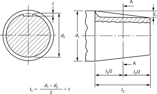
5.4.11 Dimensions of conical shaft ends with parallel keys, short series
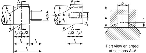
Keyway may have forms other than shown.
Conicity of 1:10 corresponds to (d1−d2)/(l2/2) = 1/10.
Dimensions in mm
| Diameter (d1) | Length | Key and key way | External thread (d3) | Internal thread (d4) | |||||
| (l1) | (l2) | (l3) | (l2) | b × h | t | t1 | |||
| 16 | 15.2 | 3 × 3 | 1.8 | M10 × 1.25 | M4 × 0.7 | ||||
| 18 | 28 | 16 | 12 | 17.2 | 4 × 4 | 2.5 | M10 × 1.25 | M5 × 0.8 | |
| 19 | 18.2 | 4 × 4 | 2.5 | M10 × 1.25 | M5 × 0.8 | ||||
| 20 | 18.9 | 4× 4 | 2.5 | M12 × 1.25 | M6 × 1.0 | ||||
| 22 | 36 | 22 | 14 | 20.9 | 4× 4 | 2.5 | M12 × 1.25 | M6 × 1.0 | |
| 24 | 22.9 | 5 × 5 | 3.0 | M12 × 1.25 | M6 × 1.0 | ||||
| 25 | 42 | 24 | 18 | 23.8 | 5×5 | 3.0 | M16 × 1.5 | M8 × 1.25 | |
| 28 | 26.8 | 5 × 5 | 3.0 | M16 × 1.5 | M8 × 1.25 | ||||
| 30 | 28.2 | 5×5 | 3.0 | M20 × 1.5 | M10 × 1.5 | ||||
| 32 | 58 | 36 | 22 | 30.2 | 6 × 6 | 3.5 | M20 × 1.5 | M10 × 1.5 | |
| 35 | 33.2 | 6 × 6 | 3.5 | M20 × 1.5 | M10 × 1.5 | ||||
| 38 | 36.2 | 6 × 6 | 3.5 | M24 × 2.0 | M12 × 1.75 | ||||
| 40 | 37.3 | 10 × 8 | 5.0 | M24 × 2 | M12 × 1.75 | ||||
| 42 | 39.3 | 10 × 8 | 5.0 | M24 × 2 | M12 × 1.75 | ||||
| 45 | 42.3 | 12 × 8 | 5.0 | M30 × 2 | M16 × 2.0 | ||||
| 48 | 82 | 54 | 28 | 45.3 | 12 × 8 | 5.0 | M30 × 2 | M16 × 2.0 | |
| 50 | 47.3 | 12 × 8 | 5.0 | M36 × 3 | M16 × 2.0 | ||||
| 55 | 52.3 | 14 × 9 | 5.5 | M36 × 3 | M20 × 2.5 | ||||
| 56 | 53.3 | 14 × 9 | 5.5 | M36 × 3 | M20 × 2.5 | ||||
| 60 | 56.5 | 16 × 10 | 6.0 | M42 × 3 | M20 × 2.5 | ||||
| 63 | 59.5 | 16 × 10 | 6.0 | M42 × 3 | M20 × 2.5 | ||||
| 65 | 105 | 70 | 35 | 61.5 | 16 × 10 | 6.0 | M42 × 3 | M20 × 2.5 | |
| 70 | 66.5 | 18 × 11 | 7.0 | M48 × 3 | M24 × 3.0 | ||||
| 71 | 67.5 | 18 × 11 | 7.0 | M48 × 3 | M24 × 3.0 | ||||
| 75 | 71.5 | 18 × 11 | 7.0 | M48 × 3 | M24 × 3.0 | ||||
| 80 | 75.5 | 20 × 12 | 7.5 | M56 × 4 | M30 × 3.5 | ||||
| 85 | 130 | 90 | 40 | 80.5 | 20 × 12 | 7.5 | M56 × 4 | M30 × 3.5 | |
| 90 | 85.5 | 22 × 14 | 9.0 | M64 × 4 | M30 × 3.5 | ||||
| 95 | 90.5 | 22 × 14 | 9.0 | M64 × 4 | M36 × 4.0 | ||||
| 100 | 94.0 | 25 × 14 | 9.0 | M72 × 4 | M36 × 4.0 | ||||
| 110 | 165 | 120 | 45 | 104.0 | 25 × 14 | 9.0 | M80 × 4 | M42 × 4.5 | |
| 120 | 114.0 | 28 × 16 | 10.0 | M90 × 4 | M42 × 4.5 | ||||
| 125 | 119.0 | 28 × 16 | 10.0 | M90 × 4 | M48 × 5.0 | ||||
| 130 | 122.5 | 28 × 16 | 10.0 | M100 × 4 | – | ||||
| 140 | 200 | 150 | 50 | 132.5 | 32 × 18 | 11.0 | M100 × 4 | – | |
| 150 | 142.5 | 32 × 18 | 11.0 | M110 × 4 | – | ||||
| 160 | 151.0 | 36 × 20 | 12.0 | M125 × 4 | – | ||||
| 170 | 240 | 180 | 60 | 161.0 | 36 × 20 | 12.0 | M125 × 4 | – | |
| 180 | 171.0 | 40 × 22 | 13.0 | M140 × 6 | – | ||||
| 190 | 179.5 | 40 × 22 | 13.0 | M140 × 6 | – | ||||
| 200 | 280 | 210 | 70 | 189.5 | 40 × 22 | 13.0 | M160 × 6 | – | |
| 220 | 209.5 | 45 × 25 | 15.0 | M160 × 6 | – | ||||

For further information see BS 4506.
5.4.12 Transmissible torque values
| Shaft end diameter d1 (mm) | Transmissible torque T (Nm) | ||
| (a) | (b) | (c) | |
| 6 | 0.307 | 0.145 | |
| 7 | 0.53 | 0.25 | |
| 8 | 0.85 | 0.4 | |
| 9 | 1.25 | 0.6 | |
| 10 | 1.85 | 0.875 | |
| 11 | 2.58 | 1.22 | |
| 12 | 3.55 | 1.65 | |
| 14 | 6.00 | 2.8 | |
| 16 | 9.75 | 4.5 | |
| 18 | 14.5 | 6.7 | |
| 19 | 17.5 | 8.25 | |
| 20 | 21.2 | 9.75 | |
| 22 | 29.0 | 13.6 | |
| 24 | 40.0 | 18.5 | |
| 25 | 46.2 | 21.2 | |
| 28 | 69.0 | 31.5 | |
| 30 | 206 | 87.5 | 40.0 |
| 32 | 250 | 109.0 | 50.0 |
| 35 | 325 | 150.0 | 69.0 |
| 38 | 425 | 200.0 | 92.5 |
| 40 | 487 | 236.0 | 112 |
| 42 | 560 | 280 | 132 |
| 45 | 710 | 355 | 170 |
| 48 | 850 | 450 | 212 |
| 50 | 950 | 515 | 243 |
| 55 | 1280 | 730 | 345 |
| 56 | 1360 | 775 | 355 |
| 60 | 1650 | 975 | 462 |
| 63 | 1900 | 1150 | 545 |
| 65 | 2120 | 1280 | 600 |
| 70 | 2650 | 1700 | 800 |
| 71 | 2780 | 1800 | 825 |
| 75 | 3250 | 2120 | 1000 |
| 80 | 3870 | 2650 | 1250 |
| 85 | 4750 | 3350 | 1550 |
| 90 | 5600 | 4120 | 1900 |
| 95 | 6500 | 4870 | 2300 |
| 100 | 7750 | 5800 | 2720 |
| 110 | 10300 | 8250 | 3870 |
| 120 | 13 700 | 11 200 | 5150 |
| 125 | 15 000 | 12 800 | 6000 |
| 130 | 17 000 | 14 500 | |
| 140 | 21 200 | 19 000 | |
| 150 | 25 800 | 24 300 | |
| 160 | 31 500 | 30 700 | |
| 170 | 37 500 | 37 500 | |
| 180 | 45 000 | ||
| 190 | 53 000 | ||
| 200 | 61 500 | ||
| 220 | 82 500 | ||
| 240 | 1 06000 | ||
| 250 | 1 18000 | ||
| 260 | 1 36000 | ||
| 280 | 1 70000 | ||
| 300 | 2 06 000 | ||
| 320 | 2 50000 | ||
| 340 | 3 00000 | ||
| 360 | 3 55 000 | ||
| 380 | 425000 | ||
| 400 | 487 000 | ||
| 420 | 5 60000 | ||
| 440 | 6 50000 | ||
| 450 | 690000 | ||
| 460 | 7 50 000 | ||
| 480 | 8 50000 | ||
| 500 | 9 50000 | ||
| 530 | 11 50 000 | ||
| 560 | 13 60 000 | ||
| 600 | 16 50 000 | ||
| 630 | 1900000 | ||

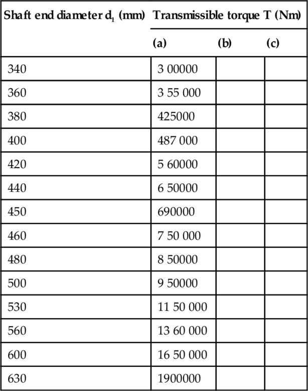
The values of transmissible torque have been calculated from the following formulae and rounded off to the values of the R80 (preferred numbers) series:
(a) Transmission of pure torque:
![]()
(b) Transmission of a known torque associated with a bending moment of a known magnitude:
![]()
(c) Transmission of a known torque associated with an undetermined bending moment:
![]()
These three formulae assume use of a steel with a tensile strength of 490 to 590 N/mm2. These values are intended to provide a rapid comparison between shafts of different sizes and not as fundamental design criteria. Steady torque conditions are assumed.
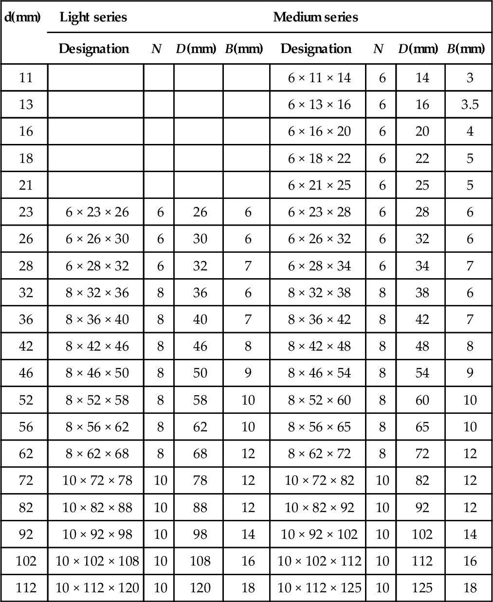
5.4.13 Straight-sided splines for cylindrical shafts, metric
Designation: nominal dimens
The profile of a splined shaft or hub is designated by stating, in the following order:
The number of splines N
The minor diameter d
The outside diameter D.
For example, shaft (or hub) 6 × 23 × 26.

| d(mm) | Light series | Medium series | ||||||
| Designation | N | D(mm) | B(mm) | Designation | N | D(mm) | B(mm) | |
| 11 | 6 × 11 × 14 | 6 | 14 | 3 | ||||
| 13 | 6 × 13 × 16 | 6 | 16 | 3.5 | ||||
| 16 | 6 × 16 × 20 | 6 | 20 | 4 | ||||
| 18 | 6 × 18 × 22 | 6 | 22 | 5 | ||||
| 21 | 6 × 21 × 25 | 6 | 25 | 5 | ||||
| 23 | 6 × 23 × 26 | 6 | 26 | 6 | 6 × 23 × 28 | 6 | 28 | 6 |
| 26 | 6 × 26 × 30 | 6 | 30 | 6 | 6 × 26 × 32 | 6 | 32 | 6 |
| 28 | 6 × 28 × 32 | 6 | 32 | 7 | 6 × 28 × 34 | 6 | 34 | 7 |
| 32 | 8 × 32 × 36 | 8 | 36 | 6 | 8 × 32 × 38 | 8 | 38 | 6 |
| 36 | 8 × 36 × 40 | 8 | 40 | 7 | 8 × 36 × 42 | 8 | 42 | 7 |
| 42 | 8 × 42 × 46 | 8 | 46 | 8 | 8 × 42 × 48 | 8 | 48 | 8 |
| 46 | 8 × 46 × 50 | 8 | 50 | 9 | 8 × 46 × 54 | 8 | 54 | 9 |
| 52 | 8 × 52 × 58 | 8 | 58 | 10 | 8 × 52 × 60 | 8 | 60 | 10 |
| 56 | 8 × 56 × 62 | 8 | 62 | 10 | 8 × 56 × 65 | 8 | 65 | 10 |
| 62 | 8 × 62 × 68 | 8 | 68 | 12 | 8 × 62 × 72 | 8 | 72 | 12 |
| 72 | 10 × 72 × 78 | 10 | 78 | 12 | 10 × 72 × 82 | 10 | 82 | 12 |
| 82 | 10 × 82 × 88 | 10 | 88 | 12 | 10 × 82 × 92 | 10 | 92 | 12 |
| 92 | 10 × 92 × 98 | 10 | 98 | 14 | 10 × 92 × 102 | 10 | 102 | 14 |
| 102 | 10 × 102 × 108 | 10 | 108 | 16 | 10 × 102 × 112 | 10 | 112 | 16 |
| 112 | 10 × 112 × 120 | 10 | 120 | 18 | 10 × 112 × 125 | 10 | 125 | 18 |
Tolerances on holes and shafts


Tolerances on symmetry
| Spline width | B | 3 | 3.5 4 5 6 | 7 8 9 10 | 12 14 16 18 |
| Tolerance of symmetry | t | 0.010 (IT7) | 0.012 (IT7) | 0.015 (IT7) | 0.018 (IT7) |

The tolerance specified on B includes the index variation (and the symmetry variation).
Notes:
(a) With certain milling cutters, it is possible for special applications to produce splines without bottom tool clearance with a very reduced fillet radius between the spline side and the minor diameter d (e.g. milling cutters with fixed working positions).
(b) The dimensional tolerances on holes and shafts relate to entirely finished workpieces (shafts and hubs). Tooling should therefore be different for untreated workpieces, or workpieces treated before machining and for workpieces treated after machining.
(c) For further information on straight sided splines and gauges for checking such splines. See BS 5686: 1986.
Involute splines
These have a similar profile to spur gear teeth. They have a much greater root strength than straight sided splines and can be produced on gear cutting machines with standard gear tooth cutters. However, their geometry and checking is much more complex than for straight sided splines and is beyond the scope of this book. See BS 3550 (inch units) and BS 6186 (metric units).
5.5 Tapers
5.5.1 Self-holding Morse and metric 5% tapers
Dimensions

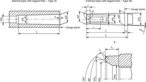
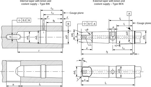

Numbers 0–6 Morse tapers and 5% metric tapers
Numbers 0–6 Morse tapers and 5% metric tapers
| Designation | Metric tapers | Morse tapers | Metric tapers | |||||||||||||
| 4 | 6 | 0 | 1 | 2 | 3 | 4 | 5 | 6 | 80 | 100 | 120 | 160 | 200 | |||
| Taper ratio | 1:20 = 0,05 | 0.624 6:12 = 1:19.212 = 0.052 05 | 0.598 58:12 = 1:20.047 = 0.049 88 | 0.599 41:12 = 1:20.02 = 0.049 95 | 0.602 35:12 = 1:19.922 = 0.050 2 | 0.623 26:12 = 1:19.254 = 0.051 94 | 0.631 51:12 = 1:19.002 = 0.052 63 | 0,62565:12 = 1:19.18 = 0.052 14 | 1:20 = 0,05 | |||||||
| External taper | D | 4 | 6 | 9.045 | 12.065 | 17.78 | 23.825 | 31.267 | 44.399 | 63.348 | 80 | 100 | 120 | 160 | 200 | |
| a | 2 | 3 | 3 | 3.5 | 5 | 5 | 6.5 | 6.5 | 8 | 8 | 10 | 12 | 16 | 20 | ||
| D1 | (1) | 4.1 | 6.2 | 9.2 | 12.2 | 18 | 24.1 | 31.6 | 44.7 | 63.8 | 80.4 | 100.5 | 120.6 | 160.8 | 201 | |
| D2 | – | – | – | – | 15 | 21 | 26 | 40 | 56 | – | – | – | – | – | ||
| d | (1) | 2.9 | 4.4 | 6.4 | 9.4 | 14.6 | 19.8 | 25.9 | 37.6 | 53.9 | 70.2 | 88.4 | 106.6 | 143 | 179.4 | |
| d1 | (2) | – | – | – | M6 | M10 | M12 | M16 | M20 | M24 | M30 | M36 | M36 | M48 | M48 | |
| d2 | (1) | – | – | 6.1 | 9 | 14 | 19.1 | 25.2 | 36.5 | 52.4 | 69 | 87 | 105 | 141 | 177 | |
| d3 | max. | – | – | 6 | 8.7 | 13.5 | 18.5 | 24.5 | 35.7 | 51 | 67 | 85 | 102 | 138 | 174 | |
| d4 | max. | 2.5 | 4 | 6 | 9 | 14 | 19 | 25 | 35.7 | 51 | 67 | 85 | 102 | 138 | 174 | |
| d8 | – | – | – | 6.4 | 10.5 | 13 | 17 | 21 | 26 | – | – | – | – | – | ||
| d9 | – | – | – | 8 | 12.5 | 15 | 20 | 26 | 31 | – | – | – | – | – | ||
| d10 | max. | – | – | – | 8.5 | 13.2 | 17 | 22 | 30 | 11.5 | – | – | – | – | – | |
| l1 | max. | 23 | 32 | 50 | 53.5 | 64 | 81 | 102.5 | 129.5 | 182 | 196 | 232 | 268 | 340 | 412 | |
| l2 | max. | 25 | 35 | 53 | 57 | 69 | 86 | 109 | 136 | 190 | 204 | 242 | 280 | 356 | 432 | |
| l3 | 0 | |||||||||||||||
| -0.1 | – | – | 56.5 | 62 | 75 | 94 | 117.5 | 149.5 | 210 | 220 | 260 | 300 | 380 | 460 | ||
| l4 | max. | – | – | 59.5 | 65.5 | 80 | 99 | 124 | 156 | 218 | 228 | 270 | 312 | 396 | 480 | |
| l7 | 0 | |||||||||||||||
| -0.1 | – | – | – | – | 20 | 29 | 39 | 51 | 81 | – | – | – | – | – | ||
| l8 | 0 | |||||||||||||||
| 0.1 | – | – | – | – | 34 | 43 | 55 | 69 | 99 | – | – | – | – | – | ||
| l11 | – | – | – | 4 | 5 | 5.5 | 8.2 | 10 | 11.5 | – | – | – | – | – | ||
| l12 | – | – | – | – | 27 | 36 | 47 | 60 | 90 | – | – | – | – | – | ||
| p | – | – | – | 3.3 | 4.2 | 5 | 6.8 | 8.5 | 10.2 | – | – | – | – | – | ||
| b | h13 | – | – | 3.9 | 5.2 | 6.3 | 7.9 | 11.9 | 15.9 | 19 | 26 | 32 | 38 | 50 | 62 | |
| c | (3) | – | – | 6.5 | 8.5 | 10 | 13 | 16 | 19 | 27 | 24 | 28 | 32 | 40 | 48 | |
| e | max. | – | – | 10.5 | 13.5 | 16 | 20 | 24 | 29 | 40 | 48 | 58 | 68 | 88 | 108 | |
| i | min. | – | – | – | 16 | 24 | 24 | 32 | 40 | 47 | 59 | 70 | 70 | 92 | 92 | |
| R | max. | – | – | 4 | 5 | 6 | 7 | 8 | 12 | 18 | 24 | 30 | 36 | 48 | 60 | |
| r | – | – | 1 | 1.2 | 1.6 | 2 | 2.5 | 3 | 4 | 5 | 5 | 6 | 8 | 10 | ||
| t | max. | 2 | 3 | 4 | 5 | 5 | 7 | 9 | 10 | 16 | 24 | 30 | 36 | 48 | 60 | |
| Internal taper | d5 | H11 | 3 | 4.6 | 6.7 | 9.7 | 14.9 | 20.2 | 26.5 | 38.2 | 54.8 | 71.5 | 90 | 108.5 | 145.5 | 182.5 |
| d6 | min. | – | – | – | 7 | 11.5 | 14 | 18 | 23 | 27 | 33 | 39 | 39 | 52 | 52 | |
| d7 | – | – | – | – | 19.5 | 24.5 | 32 | 44 | 63 | – | – | – | – | – | ||
| l5 | min. | 25 | 34 | 52 | 56 | 67 | 84 | 107 | 135 | 188 | 202 | 240 | 276 | 350 | 424 | |
| l6 | 21 | 29 | 49 | 52 | 62 | 78 | 98 | 125 | 177 | 186 | 220 | 254 | 321 | 388 | ||
| l9 | – | – | – | – | 22 | 31 | 41 | 53 | 83 | – | – | – | – | – | ||
| l10 | – | – | – | – | 32 | 41 | 53 | 67 | 97 | – | – | – | – | – | ||
| l13 | – | – | – | – | 27 | 36 | 47 | 60 | 90 | – | – | – | – | – | ||
| g | A13 | 2.2 | 3.2 | 3.9 | 5.2 | 6.3 | 7.9 | 11.9 | 15.9 | 19 | 26 | 32 | 38 | 50 | 62 | |
| h | 8 | 12 | 15 | 19 | 22 | 27 | 32 | 38 | 47 | 52 | 60 | 70 | 90 | 110 | ||
| p | – | – | – | – | 4.2 | 5 | 6.8 | 8.5 | 10.2 | – | – | – | – | – | ||
| z | (4) | 0.5 | 0.5 | 1 | 1 | 1 | 1 | 1 | 1 | 1 | 1.5 | 1.5 | 1.5 | 2 | 2 | |
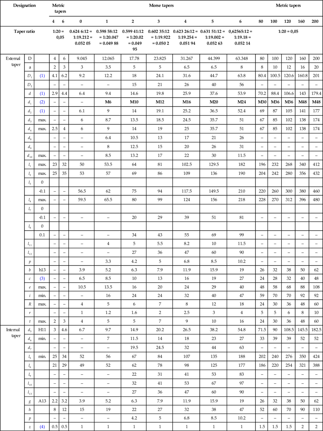
(1) For D1 and d or d2, approximate values are given for guidance. (The actual values result from the actual values of a and I1 or I3 respectively, taking into account the taper ratio and the basic size D.)
(2) d1 is the nominal thread diameter, either a metric thread M with standard pitch or, if expressly stated, a UNC thread (see table ‘Numbers 1–6 Morse tapers and Numbers 1–3 (Brown & Sharpe tapers’ for inch sizes). In every case, the appropriate symbol M or UNC shall be marked on the component.
(3) It is permissible to increase the length c over which the tenon is turned to diameter d3, but without exceeding e.
(4) z is the maximum permissible deviation, outwards only, of the position of the gauge plane related to the basic size D from the nominal position of coincidence with the leading face.
Numbers 1-6 Morse tapers and Nos 1-3 Brown & Sharpe tapers
| Designation | Brown & Sharpe tapers | Morse tapers | |||||||||
| 1 | 2 | 3 | 1 | 2 | 3 | 4 | 5 | 6 | |||
| Taper ratio | 0.502:12 = 1:23,904 = 0.041 83 | 0.502:12 = 1:23,904 = 0.041 83 | 0.502:12 = 1:23,904 = 0.041 83 | 0.598 58:12 =1:20,047 =0.049 88 | 0.599 41:12 = 1:20,02 = 0.049 95 | 0.602 35:12 = 1:19,922 = 0.050 2 | 0.623 26:12 = 1:19,254 = 0.051 94 | 0.631 51:12 = 1:19,002 = 0.052 63 | 0.625 65:12 = 1:19,18 = 0.052 14 | ||
| External taper | D | 0.239 22 | 0.299 68 | 0.375 25 | 0.475 | 0.7 | 0.938 | 1.231 | 1.748 | 2.494 | |
| a | 3/32 | 3/32 | 3/32 | 1/8 | 3/16 | 3/16 | 1/4 | 1/4 | 1/16 | ||
| D1 | (1) | 0.243 14 | 0.303 6 | 0.379 17 | 0.481 2 | 0.709 4 | 0.947 4 | 1.244 | 1.761 2 | 2.510 3 | |
| D2 | – | – | – | 0.393 7 | 0.590 6 | 0.826 8 | 1.102 4 | 1.574 8 | 2.204 7 | ||
| d | (1) | 0.2 | 0.25 | 0.312 5 | 0.369 | 0.572 | 0.778 | 1.02 | 1.475 | 2.116 | |
| d1 | (2) | – | – | – | UNC 1/4 | UNC 3/8 | UNC 1/2 | UNC 5/8 | UNC 5/8 | UNC 1 | |
| d2 | (1) | 0.189 54 | 0.236 93 | 0.296 81 | 0.353 4 | 0.553 3 | 0.752 9 | 0.990 8 | 1.438 8 | 2.063 9 | |
| d3 | max. | 11/64 | 7/32 | 9/32 | 11/32 | 17/32 | 23/32 | 31/32 | 1 13/32 | 2 | |
| d4 | max. | 11/64 | 7/32 | 9/32 | 11/32 | 17/32 | 23/32 | 31/32 | 1 13/32 | 2 | |
| d8 | – | – | – | 0.251 97 | 0.413 38 | 0.511 81 | 0.669 29 | 0.826 77 | 1.023 62 | ||
| d9 | – | – | – | 0.314 96 | 0.492 12 | 0.590 55 | 0.787 4 | 1.023 62 | 1.220 47 | ||
| d10 | max. | – | – | – | 0.334 64 | 0.519 68 | 0.689 29 | 0.866 14 | 1.181 1 | 1.417 32 | |
| l1 | max. | 15/16 | 1 3/16 | 1 1/2 | 2 1/8 | 2 9/16 | 3 3/16 | 4 1/16 | 5 3/16 | 7 1/4 | |
| l2 | max. | 1 1/32 | 1 9/32 | 1 19/32 | 2 1/4 | 2 3/4 | 3 3/8 | 4 5/16 | 5 7/16 | 7 9/16 | |
| l3 | 0 | ||||||||||
| -0.004 | 1 3/16 | 1 1/2 | 1 7/8 | 2 7/16 | 2 15/16 | 3 11/16 | 4 5/8 | 5 7/8 | 8 1/4 | ||
| l4 | max. | 1 9/32 | 1 19/32 | 1 31/32 | 2 9/16 | 3 1/8 | 3 7/8 | 4 7/8 | 6 1/8 | 8 9/16 | |
| l7 | 0 | ||||||||||
| -0.004 | – | – | – | 19/32 | 25/32 | 1 9/64 | 1 17/32 | 2 | 3 3/16 | ||
| l8 | 0 | ||||||||||
| -0.004 | – | – | – | 1 3/16 | 1 11/32 | 1 19/64 | 2 3/16 | 2 23/32 | 3 29/32 | ||
| l11 | – | – | – | 0.157 48 | 0.196 85 | 0.216 53 | 0.322 83 | 0.393 7 | 0.452 75 | ||
| l12 | – | – | – | – | 1.062 99 | 1.417 32 | 1.850 39 | 2.362 2 | 3.543 3 | ||
| p | – | – | – | 1/8 | 11/64 | 13/64 | 9/32 | 21/64 | 13/32 | ||
| b | h12 | 0.125 | 0.156 2 | 0.187 5 | 0.203 1 | 0.25 | 0.312 5 | 0.468 7 | 0.625 | 0.75 | |
| c | (3) | 1/4 | 5/16 | 3/8 | 11/32 | 13/32 | 17/32 | 5/8 | 3/4 | 1 1/16 | |
| e | max. | 0.381 | 0.455 | 0.532 | 0.52 | 0.66 | 0.83 | 0.96 | 1.15 | 1.58 | |
| i | min. | – | – | – | 1/2 | 3/4 | 0.944 88 | 1 1/4 | 1 1/4 | 1.850 4 | |
| R | max. | 3/16 | 3/16 | 3/16 | 3/16 | 1/4 | 9/32 | 5/16 | 0.472 44 | 0.708 66 | |
| r | 1/32 | 1/32 | 3/64 | 3/64 | 1/16 | 5/64 | 3/32 | 1/8 | 5/32 | ||
| t | max. | 1/8 | 1/8 | 1/8 | 3/16 | 3/16 | 1/4 | 1/4 | 5/16 | 3/8 | |
| Internal taper | d5 | H11 | 0.203 | 0.255 | 0.319 | 0.378 | 0.588 | 0.797 | 1.044 | 1.502 | 2.157 48 |
| d6 | min. | – | – | – | 9/32 | 7/16 | 9/16 | 11/16 | 11/16 | 1 1/8 | |
| d7 | – | – | – | 17/32 | 49/64 | 31/32 | 1 17/64 | 1 47/64 | 2 31/64 | ||
| l5 | min. | 1 | 1 1/4 | 1 9/16 | 2 3/16 | 2 21/32 | 3 9/32 | 4 5/32 | 5 5/16 | 7 3/8 | |
| l6 | 29/32 | 1 1/8 | 1 13/32 | 2 1/16 | 2 1/2 | 3 1/16 | 3 7/8 | 4 15/16 | 7 | ||
| l9 | – | – | – | 43/64 | 7/8 | 17/32 | 1 39/64 | 2 3/32 | 3 17/64 | ||
| l10 | – | – | – | 1 1/16 | 1 17/64 | 1 39/64 | 2 3/32 | 2 41/64 | 3 13/16 | ||
| l13 | – | – | – | – | 1.062 99 | 1.417 32 | 1.850 39 | 2.362 2 | 3.543 3 | ||
| g | H12 | 0.141 | 0.172 | 0.203 | 0.223 | 0.27 | 0.333 | 0.493 | 0.65 | 0.78 | |
| h | 13/32 | 9/16 | 23/32 | 3/4 | 7/8 | 1 1/8 | 1 1/4 | 1 1/2 | 1 7/8 | ||
| P | – | – | – | 1/8 | 11/64 | 13/64 | 9/32 | 21/64 | 13/32 | ||
| z | (4) | 0.04 | 0.04 | 0.04 | 0.039 3 | 0.039 3 | 0.039 3 | 0.039 3 | 0.039 3 | 0.039 3 | |
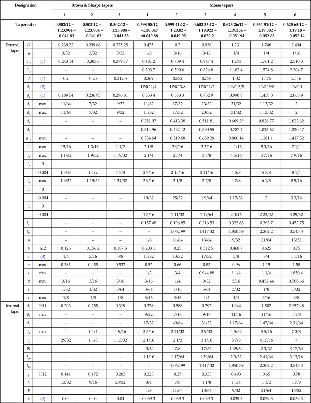
(1) For D1 and d or d2, approximate values are given for guidance. (The actual values result from the actual values of a and I1 or I3 respectively, taking into account the taper ratio and the basic size D.)
(2) d1 is the nominal thread diameter: either a UNC thread or, if expressly stated, a metric thread M with standard pitch (see table ‘Numbers 1—6 Morse tapers and 5% metric tapers’ for metric sizes). In every case, the appropriate symbol UNC or M shall be marked on the component.
(3) It is permissible to increase the length c over which the tenon is turned to diameter d3, but without exceeding e.
(4) z is the maximum permissible deviation, outwards only, of the position of the gauge plane related to the basic size D from the nominal position of coincidence with the leading face.
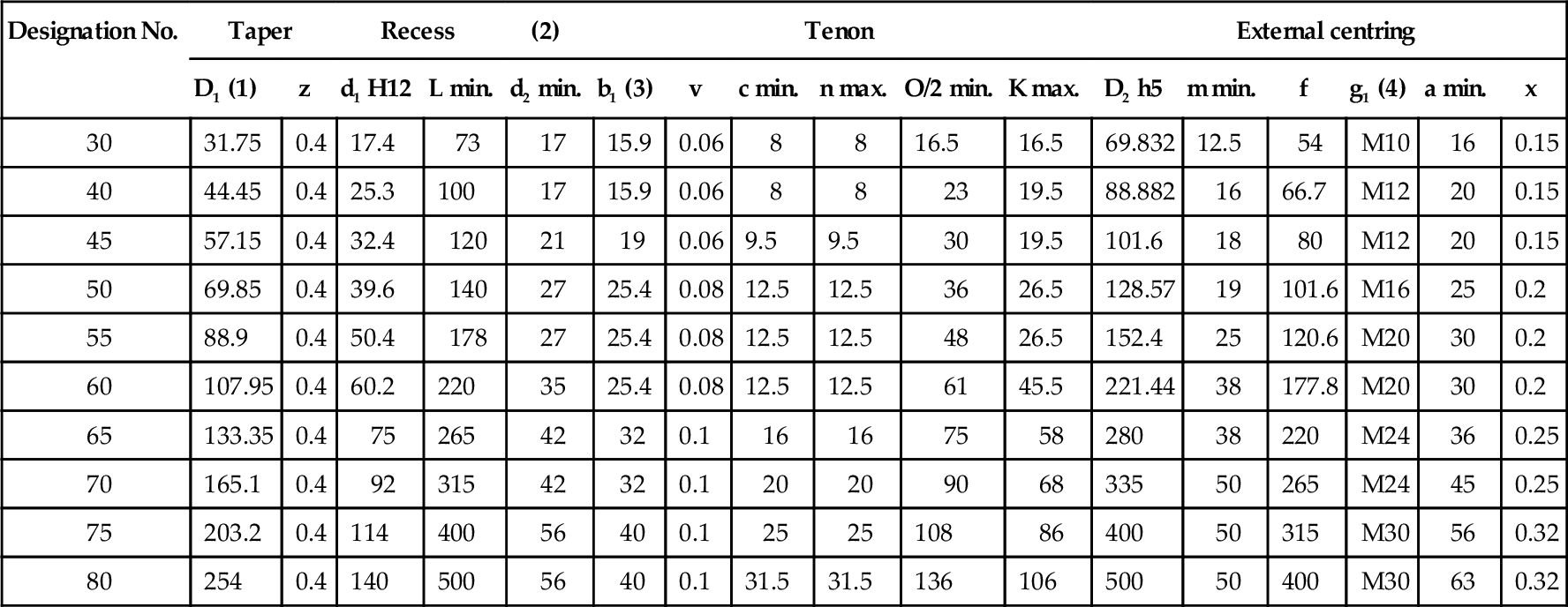
5.5.2 Tapers for spindle noses
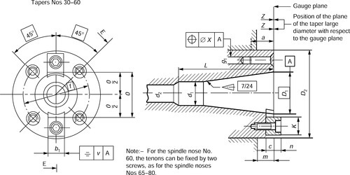

Designation and dimensions
| Designation No. | Taper | Recess | (2) | Tenon | External centring | ||||||||||||
| D1 (1) | z | d1 H12 | L min. | d2 min. | b1 (3) | v | c min. | n max. | O/2 min. | K max. | D2 h5 | m min. | f | g1 (4) | a min. | x | |
| 30 | 31.75 | 0.4 | 17.4 | 73 | 17 | 15.9 | 0.06 | 8 | 8 | 16.5 | 16.5 | 69.832 | 12.5 | 54 | M10 | 16 | 0.15 |
| 40 | 44.45 | 0.4 | 25.3 | 100 | 17 | 15.9 | 0.06 | 8 | 8 | 23 | 19.5 | 88.882 | 16 | 66.7 | M12 | 20 | 0.15 |
| 45 | 57.15 | 0.4 | 32.4 | 120 | 21 | 19 | 0.06 | 9.5 | 9.5 | 30 | 19.5 | 101.6 | 18 | 80 | M12 | 20 | 0.15 |
| 50 | 69.85 | 0.4 | 39.6 | 140 | 27 | 25.4 | 0.08 | 12.5 | 12.5 | 36 | 26.5 | 128.57 | 19 | 101.6 | M16 | 25 | 0.2 |
| 55 | 88.9 | 0.4 | 50.4 | 178 | 27 | 25.4 | 0.08 | 12.5 | 12.5 | 48 | 26.5 | 152.4 | 25 | 120.6 | M20 | 30 | 0.2 |
| 60 | 107.95 | 0.4 | 60.2 | 220 | 35 | 25.4 | 0.08 | 12.5 | 12.5 | 61 | 45.5 | 221.44 | 38 | 177.8 | M20 | 30 | 0.2 |
| 65 | 133.35 | 0.4 | 75 | 265 | 42 | 32 | 0.1 | 16 | 16 | 75 | 58 | 280 | 38 | 220 | M24 | 36 | 0.25 |
| 70 | 165.1 | 0.4 | 92 | 315 | 42 | 32 | 0.1 | 20 | 20 | 90 | 68 | 335 | 50 | 265 | M24 | 45 | 0.25 |
| 75 | 203.2 | 0.4 | 114 | 400 | 56 | 40 | 0.1 | 25 | 25 | 108 | 86 | 400 | 50 | 315 | M30 | 56 | 0.32 |
| 80 | 254 | 0.4 | 140 | 500 | 56 | 40 | 0.1 | 31.5 | 31.5 | 136 | 106 | 500 | 50 | 400 | M30 | 63 | 0.32 |
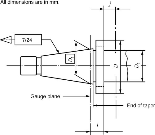
(1) D1: Basic diameter defining the gauge plane.
(2) Opening for traction bar.
(3) Assembly of the tenon in the slot: M6-h5 fit.
(4) Thread diameter g1: this is either a metric thread M with coarse pitch or, if expressly stated, a UN thread according to table ‘on thread specification’. In every case, the appropriate symbol M or UN shall be marked on the component.
Thread specification
| Designation No. | 30 | 40 | 45 | 50 | 55 | 60 | 65 | 70 | 75 | 80 |
| g1 | UN 0,375-16 | UN 0,500-13 | UN 0,500-13 | UN 0,625-11 | UN 0,750-10 | UN 0,750-10 | UN 1,000-8 | UN 1,000-8 | UN 1,250-7 | UN 1,250-7 |

Noses Nos 65–80
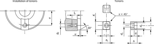
Note:– For spindle nose No. 60, the tenons can be fixed by two screws, as for the spindle noses Nos 65–80
Noses Nos 65–80

Complementary dimensions
| Designation No. | Tenon | Slot | Screws ISO 4762 | Chamfer | |||||||||||
| b1 | h max. | k max. | d5 | d4 | q | l7 | l8 | s max. | e + 0.2 | g2 | l6 | l7 | u | ||
| 30 | See Table 1(a) | 16 | 16.5 | 6.4 | 10.4 | 7 | – | – | 1.6 | 25 | M6 | 9 | – | M6 × 16 | 2 |
| 40 | 16 | 19.5 | 6.4 | 10.4 | 7 | – | – | 1.6 | 33 | M6 | 9 | – | M6 × 16 | 2 | |
| 45 | 19 | 19.5 | 8.4 | 13.4 | 9 | – | – | 1.6 | 40 | M8 | 12 | – | M8 × 20 | 2 | |
| 50 | 25 | 26.5 | 13 | 19 | 13 | – | – | 2 | 49.5 | M12 | 18 | – | M12 × 25 | 3 | |
| 55 | 25 | 26.5 | 13 | 19 | 13 | – | – | 2 | 61.5 | M12 | 18 | – | M12 × 25 | 3 | |
| 60 | 25 | 45.5 | 13 | 19 | 13 | – | – | 2 | 84 | M12 | 18 | – | M12 × 25 | 3 | |
| 25 | 45.5 | 13 | 19 | 13 | 22 | 11.7 | 2 | 73 | M12 | 18 | 22 | M12 × 25 | 3 | ||
| 65 | 32 | 58 | 17 | 25 | 17 | 28 | 15 | 2.5 | 90 | M16 | 25 | 28 | M16 × 35 | 4 | |
| 70 | 40 | 68 | 17 | 25 | 17 | 36 | 16 | 2.5 | 106 | M16 | 25 | 36 | M16 × 45 | 4 | |
| 75 | 50 | 86 | 21 | 31 | 21 | 42 | 22 | 2.5 | 130 | M20 | 30 | 42 | M20 × 55 | 4 | |
| 80 | 63 | 106 | 21 | 31 | 21 | 58 | 24 | 2.5 | 160 | M20 | 30 | 58 | M20 × 65 | 4 | |

5.5.3 Tapers for tool shanks

1) Optional groove. Without groove, cylindrical joining surface with diameter D3 = D1−0.5.
| Designation No. | Taper | Cylindrical tenon | Collar | Thread | ||||||||||||||
| D1 (1) | Z | L h12 | l1 | d1 a10 | p | d3 | y | b H12 | t max. | w | d2 | d4 max. | g (2) | l2 min. | l3 min. | l4 0-0.5 | l5 | |
| 30 | 31.75 | 0.4 | 68.4 | 48.4 | 17.4 | 3 | 16.5 | 1.6 | 16.1 | 16.2 | 0.12 | 13 | 16 | M12 | 24 | 34 | 62.9 | 5.5 |
| 40 | 44.45 | 0.4 | 93.4 | 65.4 | 25.3 | 5 | 24 | 1.6 | 16.1 | 22.5 | 0.12 | 17 | 21.5 | M16 | 32 | 43 | 85.2 | 8.2 |
| 45 | 57.15 | 0.4 | 106.8 | 82.8 | 32.4 | 6 | 30 | 3.2 | 19.3 | 29 | 0.12 | 21 | 26 | M20 | 40 | 53 | 96.8 | 10 |
| 50 | 69.85 | 0.4 | 126.8 | 101.8 | 39.6 | 8 | 38 | 3.2 | 25.7 | 35.3 | 0.2 | 26 | 32 | M24 | 47 | 62 | 115.3 | 11.5 |
| 55 | 88.9 | 0.4 | 164.8 | 126.8 | 50.4 | 9 | 48 | 3.2 | 25.7 | 45 | 0.2 | 26 | 36 | M24 | 47 | 62 | 153.3 | 11.5 |
| 60 | 107.95 | 0.4 | 206.8 | 161.8 | 60.2 | 10 | 58 | 3.2 | 25.7 | 60 | 0.2 | 32 | 44 | M30 | 59 | 76 | 192.8 | 14 |
| 65 | 133.35 | 0.4 | 246 | 202 | 75 | 12 | 72 | 4 | 32.4 | 72 | 0.3 | 38 | 52 | M36 | 70 | 89 | 230 | 16 |
| 70 | 165.1 | 0.4 | 296 | 252 | 92 | 14 | 90 | 4 | 32.4 | 86 | 0.3 | 38 | 52 | M36 | 70 | 89 | 280 | 16 |
| 75 | 203.2 | 0.4 | 370 | 307 | 114 | 16 | 110 | 5 | 40.5 | 104 | 0.3 | 50 | 68 | M48 | 92 | 115 | 350 | 20 |
| 80 | 254 | 0.4 | 469 | 394 | 140 | 18 | 136 | 6 | 40.5 | 132 | 0.3 | 50 | 68 | M48 | 92 | 115 | 449 | 20 |

(1) D1: Basic diameter defining the gauge plane.
(2) Thread diameter g: this is either a metric thread M with coarse pitch or, if expressly stated, a UN thread according to table on ‘thread specification’. In every case, the appropriate symbol M or UN shall be marked on the component.
Thread specification

5.5.4 Tool shank collars
Designation and dimensions
| Designation No. | D1 | ia, b ± 0,1 | D | D4b max. | jb, c min. |
| 30 | 31.75 | 9.6 | 50 | 36 | 9 |
| 40 | 44.45 | 11.6 | 63 | 50 | 11 |
| 45 | 57.15 | 15.2 | 80 | 68 | 13 |
| 50 | 69.85 | 97.5 | 78 | 16 | |
| 55 | 88.9 | 17.2 | 130 | 110 | |
| 60 | 107.95 | 19.2 | 156 | 136 | |
| 65 | 133.35 | 22 | 195 | By agreement between customer and supplier | |
| 70 | 165.1 | 24 | 230 | ||
| 75 | 203.2 | 27 | 280 | ||
| 80 | 254 | 34 | 350 | ||

a The distance between the front face of the collar and the gauge plane having the basic diameter D1 (and not the great base plane of the taper).
b These values are only prescribed for those tools that are intended for attachment on the collar front face.
c Tool fixing area.
5.5.5 Bridgeport R8 taper

The R8 taper was originally introduced by the Bridgeport Machine Tool Co., for their vertical spindle turret mills.
This taper is now widely adopted for the spindles of similar machines by other manufacturers and it is also used for the spindles of small, low-cost milling machines imported from the Far East.
5.6 Fluid power transmission systems
Mechanical power transmission systems depend on such devices as shafts, universal joints, gears, belts, chains, etc., to transmit energy and motion from one part of a system to another. As such they tend to be relatively inflexible. Fluid power systems, although less efficient in the use of energy, are extremely flexible and controllable. The following table compares electrical, hydraulic and pneumatic systems.
Comparisons of electrical, hydraulic and pneumatic systems
| Electrical | Hydraulic | Pneumatic | |
| Energy source | Usually from outside supplier | Electric motor or diesel driven | Electric motor or diesel driven |
| Energy storage | Limited (batteries) | Limited (accumulator) | Good (reservoir) |
| Distribution system | Excellent, with minimal loss | Limited basically a local facility | Good Can be treated as a plant wide service |
| Energy cost | Lowest | Medium | Highest |
| Rotary actuators | AC and DC motors Good control on DC motorsAC motors cheap | Low speed Good controlCan be stalled | Wide speed range Accurate speed control difficult |
| Linear actuator | Short motion via solenoid Otherwise via mechanical conversion | Cylinders Very high force | Cylinders Medium force |
| Controllable force | Possible with solenoid and DC motors Complicated by need for cooling | Controllable high force | Controllable medium force |
| Points to note | Danger from electric shock | Leakage dangerous and unsightly Fire hazard | Noise |

Source: Table 1.1 in Hydraulics & Pneumatics, 2nd edn. Andrew Parr: B/Heinemann.
This section is concerned only with fluid power transmission, that is pneumatic (gases: usually air) and hydraulic (liquids: mainly oil or water). The main advantages and disadvantages of such systems arise out of the different characteristics of low density compressible gases and (relatively) high density incompressible liquids. A pneumatic system, for example, tends to have a ’softer’ action than a hydraulic system which is more positive. A pneumatic system also exhausts to the atmosphere and this simplifies the pipework since no return circuit is required. A liquid-based hydraulic system can operate at much higher pressures and can provide much higher forces. Hydraulic systems employ water as the operating fluid where large volumes are required as in operating the raising and lowering mechanism of Tower Bridge in London or in the lift bridges employed mainly on the canal systems and waterways of continental Europe. However for most industrial purposes the hydraulic fluid is oil which is self-lubricating and does not cause corrosion.
5.6.1 A typical pneumatic system
The following figure is a schematic diagram of a pneumatic system. Air is drawn from the atmosphere via an air filter and raised to the required pressure by an air compressor which is usually driven by an electric motor (portable compressors as used by the construction industry have the air compressor driven by a diesel engine). The compression process raises the temperature of the air. Air also contains a significant amount of water vapour. Before passing to the compressed air to the receiver (storage reservoir) the air must be cooled and this results in any water vapour present condensing out. This condensate should be removed before the air reaches the receiver. A pressure regulator switch turns the motor on when the pressure in the receiver falls and turns the motor off when the air reaches a predetermined pressure. The receiver is also fitted with a safety valve in case the pressure regulator switch fails. This safety valve must be capable of passing the full output of the compressor. The receiver is usually followed by a lubricator which allows an oil mist to enter the air stream and lubricates the control valve and actuator. In the simplest system the air passes to a control valve followed by the actuator: generally a piston and cylinder to provide linear motion.

Operating pressures in a pneumatic system are much lower than those used in hydraulic systems. A typical pneumatic system pressure being about 10 bar which will provide a force of 98.1 kNcm2cm of piston area. Therefore actuators in pneumatic systems need to be much larger than those used in hydraulic systems to move the same loads. The compressibility of air makes it necessary to store a large volume of air in a receiver to be drawn upon by the actuator as and when required. Without this reservoir of air there would be a slow and pulsating exponential rise in pressure with a corresponding slow and pulsating piston movement when the regulating valve is first opened. Most industrial installations require the compressed and conditioned air to be piped round the factory from the receiver to the various points where it will be required. Plug-in sockets are provided at each outlet point to receive the hose attached to the appliance (drill, rivet gun, nibbler, etc.). The socket is self sealing, so that there is no loss of air and pressure, when the hose is disconnected.
5.6.2 A typical hydraulic system
The following figure shows a typical hydraulic installation. This generally uses oil (water is only used for very large scale installations) as the activating fluid. Unlike the pneumatic system, discussed in Section 5.6.1, a hydraulic system must form a closed loop so that after passing through the actuator it returns to the oil storage tank for re-use. Further, hydraulic installations are usually single purpose, integrated installations that operate a single device, for example, the table traverse of a surface grinding machine or for powering a mobile crane. Hydraulic fluid is never piped around a whole factory to provide a ’supply on demand system’ like compressed air. Hydraulic systems work at much higher pressures, typically 150 bar compared to 10 bar for a pneumatic system, therefore the actuator (cylinder and piston or hydraulic motor) can be considerably smaller that its pneumatic counterpart for a given application. Further, since oil or water is virtually incompressible hydraulic systems are much more positive than pneumatic systems.
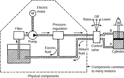
Fluid (oil or water) is drawn from the storage tank via a filter to the motor driven pump. On a machine tool this is driven by an electric motor, whilst on a crane or other mobile device it is driven by a diesel engine. Unlike a compressor the pump runs all the time that the machine is in use. If the oil pressure builds up beyond a safe predetermined value a pressure regulating valve returns the surplus oil to the storage tank. If an oil cooler is not fitted in the system then the capacity of the storage tank must be such that the oil has time to cool down an does not drop in viscosity. The piston movement is controlled by a three position changeover valve as shown. Oil is admitted at a point A to raise the piston (and the load W). Any oil already in the cylinder can escape via B and return to the storage tank via the valve. Oil is admitted to point B to lower the load and any oil already in the cylinder is allowed to escape via point A and return to the cylinder. The speed of movement can be controlled by the volume flow rate; that is the amount the valve ports are opened by the operator. This ability to provide precise control at low speeds is one of the main advantages of hydraulic systems. In the centre position, the valve locks the fluid into the cylinder on each side of the piston so that it cannot move unless leakage occurs.
The regulator bypasses the excess oil still being pumped back to the storage tank. When oil is used as the actuating fluid the system is self-lubricating.
For large scale systems, particularly when using water to reduce costs, very large volumes of water are required at very high pressures for example when raising and lowering Tower Bridge in London. Since this operation is only required at relatively infrequent intervals it would be uneconomical to employ a pump big enough to drive the operating rams directly. The solution is to install a hydraulic accumulator as shown in following figure between the pump and the operating valve and rams. The hydraulic accumulator consists of a large cylinder and ram carrying a heavy mass to provide the required pressure. The size of the cylinder and ram depends on the volume of fluid required to operate the actuating rams of (in this example) the bridge. The pressure is controlled by the mass bearing down on the accumulator. A relatively small and economic pump providing the hydraulic fluid at the required pressure but at a low delivery volume rate is used to raise the accumulator when the system is not being used. The accumulator, alone, provides the pressure fluid on demand to actuate the operating rams.

Water is forced by a pump past the valve A into the cylinder B. This raises the heavily loaded ram C. Meantime valve D is closed. The water cannot escape from B by the valve A, for the pressure upon the top closes it. So water under pressure is stored in the accumulator. When it is desired to work the press the valve D is opened and the water is forced from cylinder B into E. This raises the ram F, and compresses the bale of cotton, or whatever it may be, between the faces H and K.
Hydraulic press and accumulator.
5.6.3 Air compressor types
Piston compressors
These can deliver compressed air to suit the requirements of any system. They can also deliver air at higher pressures than vane and screw compressors. On the downside, they are noisier than vane and screw compressors and their output pulsates and requires to be fed into a receiver to smooth out the flow. Single cylinder compressors are the worst in this respect. Multistage piston compressors are more efficient due mainly to intercooling between the stages. They are capable of higher maximum pressures.
Diaphragm compressors
These are small scale inexpensive reciprocating type compressors of limited output capable of delivering oil-free air for very small systems. Since the air is free from oil they are widely used for small scale spray painting and air-brush applications. They are usually used for portable, stand-alone compressors, by contractors on site for powering such devices as staple guns.
Rotary vane compressors
These are quiet, inexpensive and deliver a steady stream of compressed air without pulsations associated with the piston and diaphragm types. Lubrication of the vane edges is required by a recirculating lubrication system, with the oil being purged from the air before delivery. Multistage vane compressors are available with intercooling between the stages where higher pressures and larger volumes of air are required. The principle operation is shown in following figure.

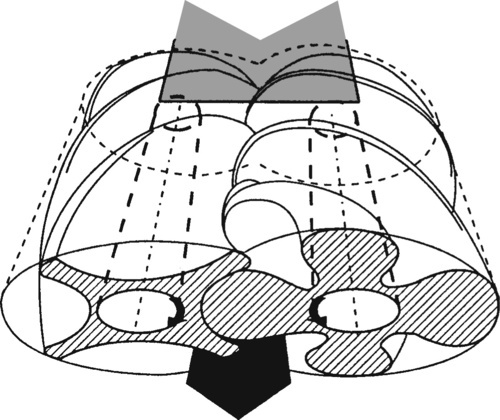
Screw compressors
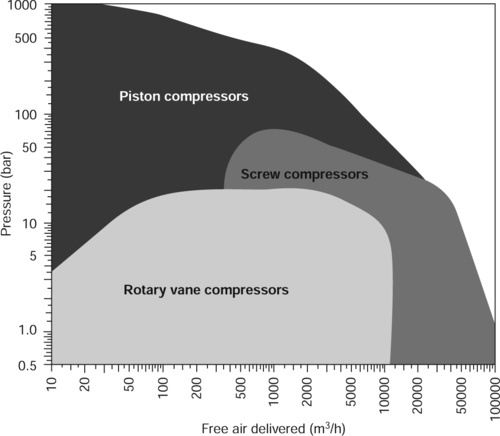
These are quiet, efficient but expensive and are usually chosen to supply large scale factory installations The principle of operation is shown in figure ‘the screw compressor’. It can be seen that a rotor with male lobes meshes with a smaller diameter rotor with female lobes. Oil not only lubricates the bearings but also seals the clearances between the rotors and cools the air before purged from the air at the point of discharge. The figure ‘compressor types: typical scope’ shows the scope of the main types of compressor described above.
5.6.4 Hydraulic pumps
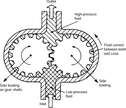
Gear pumps
These are the simplest and most robust positive displacement pump, having just two moving parts as shown in figure ‘gear pump’. Only one gear needs to be driven by the power source. The direction of rotation of the gears should be noted since they form a partial vacuum as they come out of mesh, drawing fluid into the inlet chamber. The oil is carried round between the gear teeth and the outer casing of the pump resulting in a continuous supply of oil into the delivery chamber. The pump displacement, the volume of fluid delivered, is determined by the volume of fluid between each pair of teeth and the speed of rotation. The pump delivers a fixed volume of fluid for each rotation and the outlet port pressure is determined by the ‘back-pressure’ opposing the flow in the rest of the system. This type of pump is used up to pressures of about 150 bar and about 6750 l/min. At 90% the volumetric efficiency is the lowest of the pump types to be described in the section. There are a number of variations on the gear pump available including the internal gear pump and the lobe pump. A lobe pump is shown in figure ‘the lobe pump’.

Vane pumps
The relatively low volumetric efficiency of the gear type pump stems from clearances between the teeth, and between the gears and the outer casing. These sources of leakage are largely over come in vane type pumps by the use of spring loaded vanes as shown in figure ‘unbalanced vane pump’. Vane type hydraulic pumps are similar in principle to the vane type compressor described in Section 5.6.3 except that when delivering oil they are self-lubricating. An alternative design is shown in figure ‘balanced vane pump’.

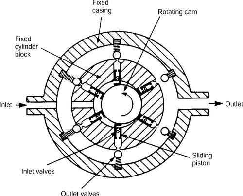
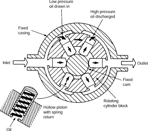
Piston pumps
Reciprocating force pumps are only used on very large scale applications in conjunction with an accumulator to smooth out the pulsations. Nowadays, for most applications requiring multiple piston pumps, the pistons and cylinders are arranged radially as shown in figure ‘radial piston pump’. The pump consists of several hollow pistons inside a stationary cylinder block. Each piston has spring loaded inlet and outlet valves. As the cam rotates, fluid is transferred relatively smoothly from the inlet port to the outlet port. The pump shown in figure ‘piston pump with stationary can and rotating block’ is similar in principle but uses a stationary cam and a rotating cylinder block. This arrangement removes the need for multiple inlet and outlet valves and is consequently more simple, reliable and cheaper to manufacture and maintain, hence this is the more commonly used type.
Axial (swash plate) pumps
This is also a multiple piston pump. The pistons are arranged in a rotating cylinder block so that they are parallel to the axis of the drive shaft as shown in following figure. The piston stroke is controlled by an angled swash plate as shown. Each piston is kept in contact with the swash plate by spring pressure or by a rotating shoe plate linked to the swash plate. Pump capacity is controlled by altering the angle of the swash plate. The larger the angle the greater the rate of flow for a given speed of rotation. The maximum swash plate angle is limited by the maximum designed piston stroke length. Zero flow rate is achieved when the swash plate is perpendicular to the drive shaft. Reversing the swash plate angle reverses the direction of fluid flow through the pump.

All types of piston pumps have very high volumetric efficiency and can be used at the highest hydraulic pressures. They are more complex than vane and gear pumps and are, therefore more expensive in first cost and to maintain. The following table compares the advantages and limitations of various types of hydraulic pumps.
Comparison of hydraulic pump types
| Type | Maximum pressure (bar) | Maximum flow (l/min) | Variable displacement | Positive displacement |
| Centrifugal | 20 | 3000 | No | No |
| Gear | 175 | 300 | No | Yes |
| Vane | 175 | 500 | Yes | Yes |
| Axial piston (port-plate) | 300 | 500 | Yes | Yes |
| Axial piston (valved) | 700 | 650 | Yes | Yes |
| In-line piston | 1000 | 100 | Yes | Yes |
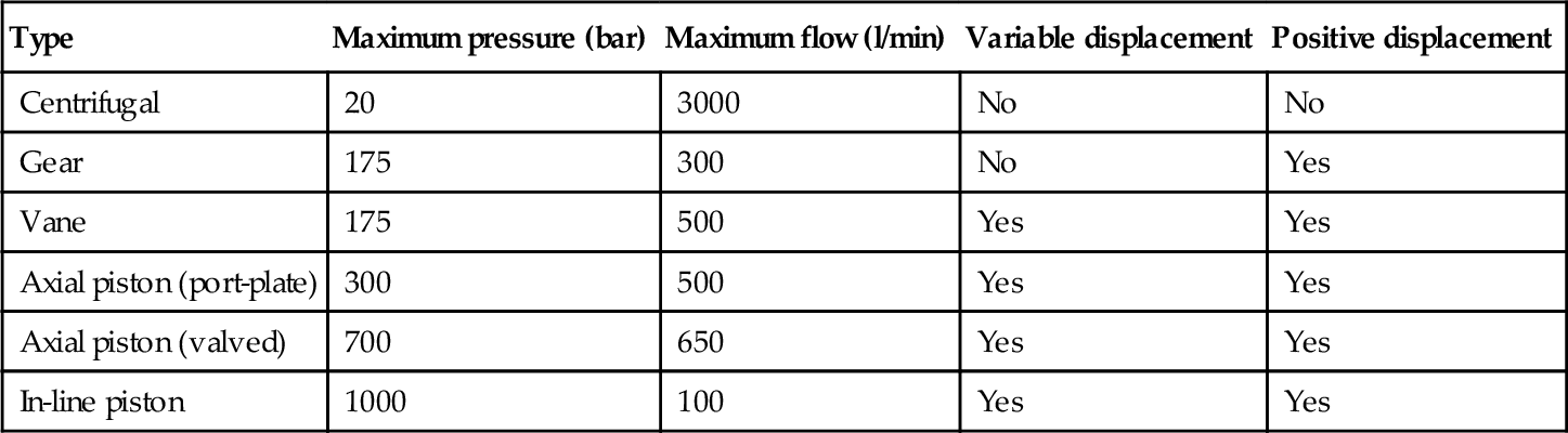
Source: Table 2.1 in Hydraulics & Pneumatics, Andrew Parr: B/Heinemann.
Specialist pumps are available for pressures up to about 7000 bar at low flows. The delivery from centrifugal and gear pumps can be made variable by changing the speed of the pump motor with a variable frequency (VF) drive.
5.6.5 Actuators (linear)
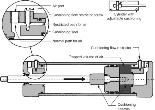
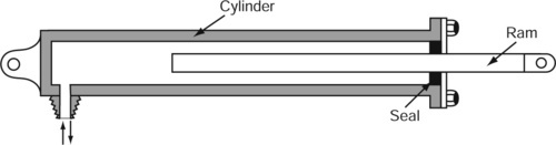
Both pneumatic and hydraulic systems use linear actuators where motion is required in a straight line as in clamping and operating machine tool work tables. Such devices have a piston and cylinder where short strokes are required. They are essentially the same design for both pneumatic and hydraulic applications except that hydraulic actuators are more heavily constructed to withstand the higher pressures and forces associated with hydraulic systems. They may be single acting as shown in figure ’single-acting cylinder’, double acting as shown in figure ‘double-acting cylinders’ or with adjustable cushioning as shown in figure ‘adjustable cushioning’. Hydraulic devices often require long-stroke actuators. These are called rams and a typical configuration is shown in figure ‘long-stroke hydraulic ram and cylinder’. It is single acting and relies on the back-force of the load being moved for the return stroke. The range of such devices is too great to list in this book and the reader is referred to Appendix 3 for the details of suppliers who can provide comprehensive catalogues. Wherever possible pneumatic and hydraulic clamping devises should be designed so that the clamping force is not reduced or removed (unlocked) in the event of a system failure.


5.6.6 Actuators (rotary)
These are similar in construction to the compressors and pumps described earlier. The direction of rotation depends on the direction of the fluid flow.
Pneumatic
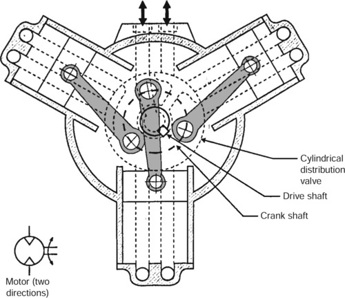
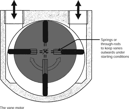
For general applications these can be the radial piston and cylinder type as shown in figure ‘the piston motor’ where high power at moderate speeds is required. They are bulky, costly and noisy and require a silencer fitted to the exhaust system. A cheaper and lighter solution where lower power and higher speeds are required is the vane motor as shown in figure ‘the vane motor’. For applications, such as small portable drills, die-grinders and dental type drills for fine instrument work air turbines are available.
Hydraulic
Gear motors and vane motors are the most widely used. These are similar to the gear and vane type pumps described earlier. The direction of rotation depends on the direction of fluid flow.
5.6.7 Hybrid actuator systems
Hybrid drives are also available where the rotary motion of a pneumatic or hydraulic motor drives a rack and pinion mechanism provide linear motion. Where extremely long linear travels are required, a chain wheel can be substituted for the gear and roller chain can be substituted for the rack. Alternatively the pneumatic or hydraulic motor can be used to drive a lead screw and nut. This latter solution has the advantage that over-run is impossible if the motor fails and it is therefore fail-safe.
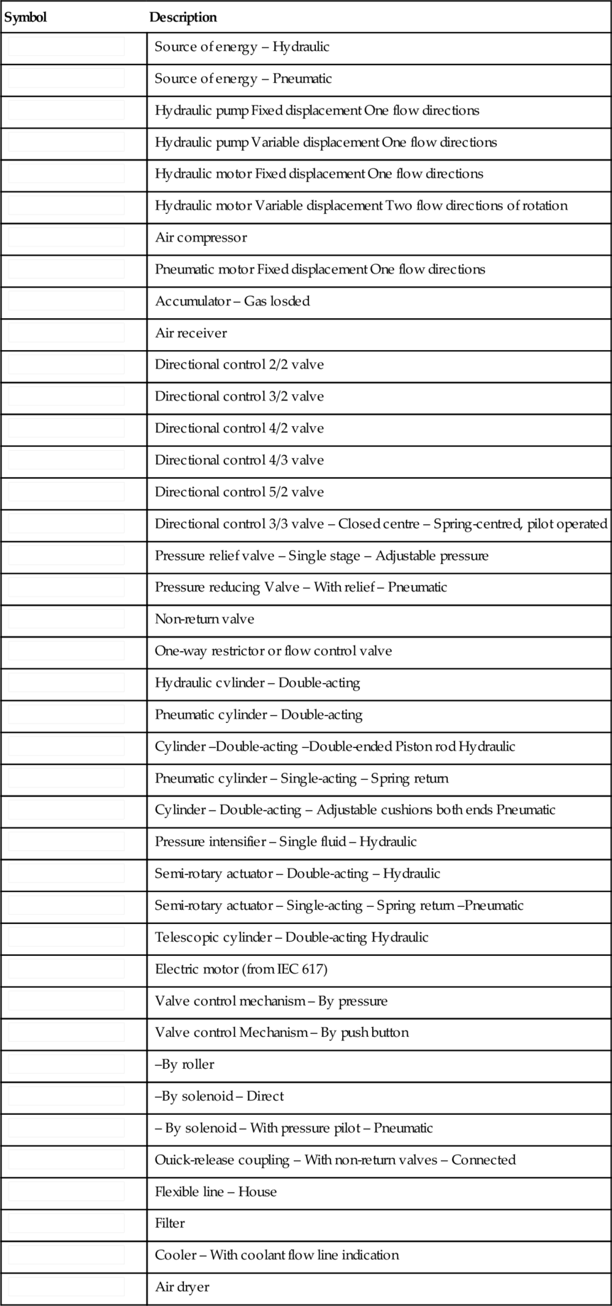
5.6.8 Symbols for fluid power systems
The following design data is provided by courtesy of the British Fluid Power Association. Some of the more widely used symbols for fluid power systems are shown in the following figure. For the full range of graphic symbols the reader is referred to ISO 1219-1 as amended in 1991. For the rules relating to circuit layout see ISO 1219-2. For port identification and operator marking see ISO 9461 (hydraulic) or CETOP RP68P (pneumatic) or ISO 5599 (pneumatic).
Hydraulic and pneumatic symbols.
| Symbol | Description |
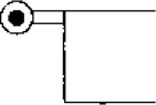
| Source of energy – Hydraulic | |
| Source of energy – Pneumatic | |
 | Hydraulic pump Fixed displacement One flow directions |
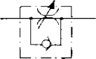
 | Hydraulic pump Variable displacement One flow directions |
 | Hydraulic motor Fixed displacement One flow directions |
 | Hydraulic motor Variable displacement Two flow directions of rotation |
 | Air compressor |
 | Pneumatic motor Fixed displacement One flow directions |
 | Accumulator – Gas losded |
 | Air receiver |
 | Directional control 2/2 valve |
 | Directional control 3/2 valve |
 | Directional control 4/2 valve |
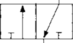
 | Directional control 4/3 valve |
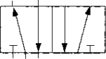 | Directional control 5/2 valve |
 | Directional control 3/3 valve – Closed centre – Spring-centred, pilot operated |
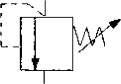 | Pressure relief valve – Single stage – Adjustable pressure |
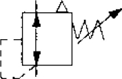 | Pressure reducing Valve – With relief – Pneumatic |
 | Non-return valve |
 | One-way restrictor or flow control valve |
 | Hydraulic cvlinder – Double-acting |
 | Pneumatic cylinder – Double-acting |
 | Cylinder –Double-acting –Double-ended Piston rod Hydraulic |
 | Pneumatic cylinder – Single-acting – Spring return |
 | Cylinder – Double-acting – Adjustable cushions both ends Pneumatic |
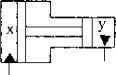 | Pressure intensifier – Single fluid – Hydraulic |
 | Semi-rotary actuator – Double-acting – Hydraulic |
 | Semi-rotary actuator – Single-acting – Spring return –Pneumatic |
 | Telescopic cylinder – Double-acting Hydraulic |
 | Electric motor (from IEC 617) |
 | Valve control mechanism – By pressure |
 | Valve control Mechanism – By push button |
 | –By roller |
 | –By solenoid – Direct |
 | – By solenoid – With pressure pilot – Pneumatic |
 | Ouick-release coupling – With non-return valves – Connected |
| Flexible line – House | |
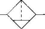 | Filter |
 | Cooler – With coolant flow line indication |
 | Air dryer |
5.6.9 Fluid power transmission design data (general formulae)
Hydraulic
(a) Pumps and motors
(b) Cylinders

F = force (N)
A = area (m2)
v = velocity (m/s)
p = pressure (bar)
D = displacement (cm3/rev)
n = rev/min
(c) Flow
Δ = pressure change (bar)
That is, if you double the flow you get 4 times the pressure change
Pressure loss in pipes
| Flow in l/min | Tube bore size (mm) | ||||||||
| 5 | 7 | 10 | 13 | 16 | 21 | 25 | 30 | 36 | |
| 1 | 0.69 | 0.22 | |||||||
| 2 | 1.38 | 0.44 | |||||||
| 3 | 2.07 | 0.66 | 0.17 | ||||||
| 5 | 4.14 | 1.24 | 0.24 | ||||||
| 7.5 | 6.55 | 1.72 | 0.31 | ||||||
| 10 | 3.10 | 0.38 | 0.14 | ||||||
| 15 | 5.38 | 0.69 | 0.21 | 0.08 | |||||
| 20 | 1.10 | 0.30 | 0.14 | ||||||
| 30 | 2.21 | 0.69 | 0.25 | 0.04 | |||||
| 40 | 1.17 | 0.45 | 0.08 | 0.04 | |||||
| 50 | 0.59 | 0.12 | 0.07 | 0.03 | |||||
| 75 | 1.31 | 0.23 | 0.14 | 0.06 | 0.02 | ||||
| 100 | 0.41 | 0.22 | 0.13 | 0.03 | |||||
| 150 | 0.45 | 0.23 | 0.06 | ||||||
| 200 | 0.41 | 0.10 | |||||||
| 250 | 0.16 | ||||||||
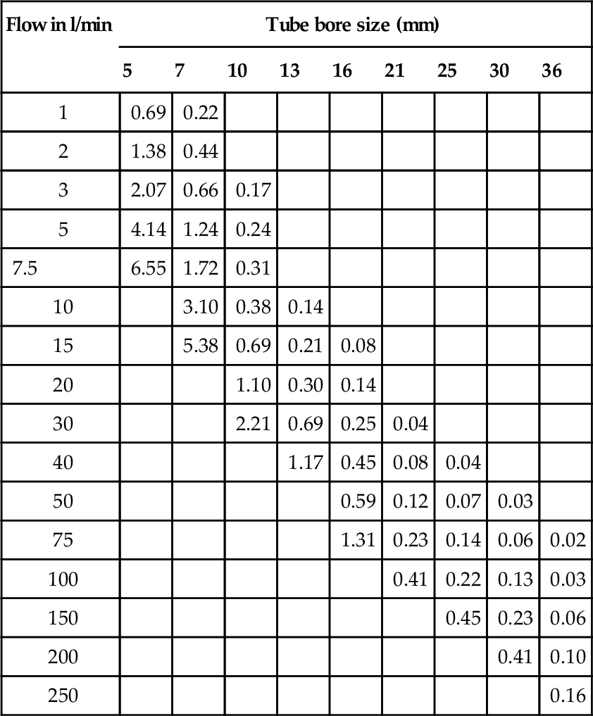
This chart gives the approximate pressure drop in smooth bore straight pipes, in bar per 3 m length. Bends and fittings will increase the above pressure losses and manufacturers should be consulted for more accurate figures.
Pneumatic
(a) Flow through pipes
![]()
Where:
Δp = pressure drop(bar)
Q = free air flow (m3/s)= l/s × 10−3
L = pipe length (m)
d = internal diameter of pipe
(b) Velocity through pipes
![]()
v = flow velocity (m/s)
p = initial pressure (bar)
d = inside pipe diameter (mm)
If the free air flow is known, the minimum inside diameter to keep velocity below 6 m/s, can be found fromml:
![]()
For normal installations, where the pressure is about seven bar gauge, this can be simplified to:
d (mm) should be greater than ![]()
Source: Pages 14 & 15 BFPA Data books.
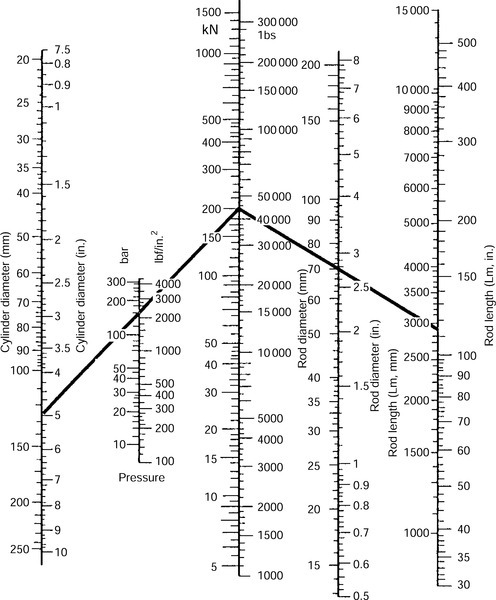
5.6.10 Fluid power transmission design data (hydraulic cylinders)
Output force and maximum rod lengths
Example: Knowing the output force required (200 kN) and the pressure of the system (160 bar), connect Output force through pressure to cut cylinder diameter.
Answer: 125 mm.
To find the maximum length of a piston rod. Connect output force required (200 kN) through rod diameter (70 mm) to cut the maximum rod length scale; this gives you the (Lm) dimensions.
Answer: 2800 mm.
To find the actual length stroke (LA) for a specific mounting use formulae below.
Maximum stroke lengths for specific mounting cases
| Foot mounted, eye rod end | LA = Lm × 0.8 |
| Foot mounted, rigidly supported rod | LA = Lm |
| Front flange, eye rod end | LA = Lm × 0.8 |
| Front flange, rigidly supported rod | LA = Lm |
| Rear flange, eye rod end | LA = Lm × 0.4 |
| Real flange, rigidly supported rod | LA = Lm × 0.8 |
| Rear eye, eye rod end | LA = Lm × 0.3 |
| Trunnion head end, eye rod end | LA = Lm × 0.3 |
| Trunnion gland end, eye rod end | LA = Lm × 0.6 |
| Trunnion gland end, rigidly supported end | LA = Lm × 0.8 |
For intermediate trunnion positions scaled multiplier factors must be taken. Clevis and spherical eye mountings have the same factor as eye mountings.
Example: Having found Lm (2800 mm) for rear flange mount with eye rod end LA = Lm × 0.4 = 2800 × 0.4 = 1120 mm.
Source: Page 16 BFPA data book.
5.6.11 Fluid power transmission design data (hydraulic pipes and hoses)
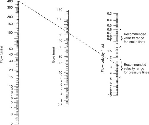
Nomogram for determining pipe sizes in relation to flow rates and recommended velocity ranges.
![]()
where d = bore of pipe (mm)
Recommended velocity ranges based on oils having a maximum viscosity grade of 70cSt at 40°C and operating between 18°C and 70°C.
Note: For pipe runs greater than 10 m pipe size should be increased correspondingly. Intake line should never exceed 1 m long.
| BFPA/P7 | Guidelines to the selection and application of tube couplings for use in fluid power systems. |
| BFPA/P47 | Guidelines for the use of fluid power hose assemblies. |
Source: Page 17 BFPA design data book.
5.6.12 Fluid power transmission design data (hydraulic fluids, seals and contamination control)
Fluids
ISO Classification of Hydraulic Fluids – BS ISO 6743-4
| HH | Non inhibited refined mineral oils |
| HL | Refined mineral oils with improved anti-rust and anti-oxidation properties |
| HM | Oils of HL type with improved anti-wear properties |
| HV | Oils of HM type with improved viscosity/temperature properties |
| HFAE | Oil in water emulsions |
| HFAS | Chemical solutions in water |
| HFB | Water-in-oil emulsions |
| HFC | Water polymer solutions |
| HFDR | Synthetic fluids of the phosphate ester type |
Ecologically acceptable hydraulic fluids
Viscosity Classification of Hydraulic Fluids – ISO 3448 (BS 4231)
Each viscosity grade is designated by the nearest whole number to its mid-point kinematic viscosity in centistokes at 40°C. It is abbreviated ISOVG … Common viscosity grades of hydraulic fluids are VG5, 10, 22, 32, 46, 68, 100, 150, 220 and 320.
Thus HM32 is a mineral oil with improved anti-rust, anti-oxidation and anti-wear properties having a viscosity of approximately 32 centistokes at 40°C.
For further details of specific fluids see BFPA/P12, Mineral oil data sheets and BFPA/P13, Fire resistant fluids data sheets, BFPA/P67 Ecologically acceptable hydraulic fluids data sheets.
Seals
| Seal material | Recommended for | |
| Acrylonitrile butadiene | (NBR) | air, oil, water, water/glycol |
| Polyacrylate rubber | (ACM) | air, oil |
| Polyurethane | (AU, EU) | air, oil |
| Fluorocarbon rubber | (FKM) | air, oil water, water/glycol, chlorinated hydrocarbons, triaryl phosphates |
| Silicone | (VOM) | air, oil, chlorinated hydrocarbons |
| Styrene Butadiene | (SBR) | air, water, water/glycol |
| Ethylene propylene diene | (EPDM) | air, water, water/glycol, phosphate ester |
| Polytetrafluorethylene | (PTFE) | air, oil, water, water/glycol, phosphate ester |
For full details of seal compatibilities, see ISO 6072: Hydraulic fluid power, compatibility between elastomeric materials and fluids or BS 7714: Guide for care and handling of seals for fluid power applications. For recommendation of O-ring seal standards, see BFPA/P22 ‘Industrial O–ring Standards – Metric vs Inch.'
Source: Pages 18–20 inclusive, BFPA data book.
Fluid cleanliness
The presence of particulate contamination ('dirt') is the single most important factor governing the life and reliability of fluid power systems. Operating with clean fluids is essential. Advice on contamination control can be gained from guide line document BFPA/P5.
Contamination control
Specification of Degree of Filtration – ISO 4572 (BS 6275/1)
The multipass test, ISO 4572 (BS 6275/1), was introduced to overcome the difficulties in comparing the performance of filters. The element is subjected to a constant circulation of oil during which time fresh contaminant (ISO Test Dust) is injected into the test rig. The contaminant that is not removed by the element under test is recirculated thereby simulating service conditions.
The filtration ratio β of the filter is obtained by the analysis of fluid samples extracted from upstream and downstream of the test filter, thus
![]()
The rating of a filter element is stated as the micrometer size where βx is a high value (e.g. 100 or 200)
Fluid cleanliness standards
The preferred method of quoting the number of solid contaminant particles in a sample is the use of BS ISO 4406.
The code is constructed from the combination of two range numbers selected from the following table. The first range number represents the number of particles in a millilitre sample of the fluid that are larger than 5 μm, and the second number represents the number of particles that are larger than 15 μm.
| Number of particles per millilitre | Scale number | |
| More than | up to and including | |
| 10000 | 20000 | 21 |
| 5 000 | 10 000 | 20 |
| 2 500 | 5000 | 19 |
| 1 300 | 2500 | 18 |
| 640 | 1300 | 17 |
| 320 | 640 | 16 |
| 160 | 320 | 15 |
| 80 | 160 | 14 |
| 40 | 80 | 13 |
| 20 | 40 | 12 |
| 2.5 | 5 | 9 |
| 1.3 | 2.5 | 8 |
| 0.64 | 1.3 | 7 |

For example code 18/13 indicates that there are between 1300 and 2500 particles larger than 5 µm and between 40 and 80 particles larger than 15 µm.
For further details and comparisons of ISO 4406 with other cleanliness classes, see BFPA/P5 – Guidelines to contamination control in fluid power systems.
Flushing
Formula for flow required to adequately flush an hydraulic systemml:
![]()
Q = flow (l/min)
v = kinematic viscosity (cSt)
d = pipe bore (mm)
For further information on flushing see BFPA/P9 – Guidelines to the flushing of hydraulic systems.
Cleanliness of components
Three methods exist for measuring the cleanliness of components: test rig, flush test, strip and wash. The level of cleanliness required must be agreed between the supplier and customer but the methods are fully described in BFPA/P48 – Guidelines to the cleanliness of hydraulic fluid power components.
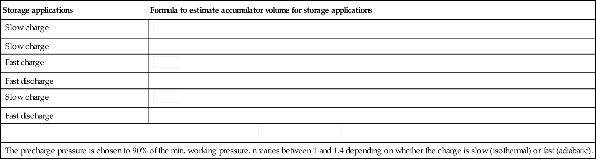
5.6.13 Fluid power transmission design data (hydraulic accumulators)
Storage applications
| Storage applications | Formula to estimate accumulator volume for storage applications |
| Slow charge |  |
| Slow charge | |
| Fast charge |  |
| Fast discharge | |
| Slow charge |  |
| Fast discharge | |
 | |
| The precharge pressure is chosen to 90% of the min. working pressure. n varies between 1 and 1.4 depending on whether the charge is slow (isothermal) or fast (adiabatic). | |
Pump pulsation
Pump pulsation and Formula to size accumulator to reduce pump pulsations.
(a) Minimum effective volume (l) ![]()
Note: It is good engineering practice to select an accumulator with port connection equal to the pump port connection.
(b) To check the level of pulsation obtained.
Volume of fluid entering accumulator = D · C
For pulsation damping precharge pressure P1 = 0.7 · P2 and assuming change from P1 to P2 is isothermal, then V2 = 0.7 · V1

Hence: Percentage pulsation above and below mean is ![]()
| V1 = effective gas volume | Va = V3 − V2 = working volume (fluid) |
| V2 = min. gas volume | k = a constant* |
| V3 = max. gas volume | Q = pump flow (l/min) |
| p1 = pre charge pressure | n = pump speed (rpm) if n > 100 use 100 |
| p2 = min. working pressure | D = pump displacement (l/rev) |
| p3 = max. working pressure | C = a constant* |
Source: Page 21 BFPA data book.
* Dependent on no. of pistons. For multi-piston pumps > 3 pistons. k = 0.45 and C= 0.013.
5.6.14 Fluid power transmission design data (hydraulic cooling and heating)
Cooling
The tank cools the oil through radiation and convection.
![]()
where:
k = 12 at normally ventilated space
24 W/m2 °C at forced ventilation
6 at poor air circulation
Required volume of water flow through the cooler:
![]()
Heating
Heating is most necessary if the environmental temperature is essentially below 0°C.
![]()
Energy
![]()
M = Mass (kg)
C = Specific heat capacity J/kg°C
ΔT1 = temperature difference (°C) fluid/air
ΔT2 = increase in fluid temperature (°C)
Δt = time (min)
Note: 1 MJ = 0.2777 kW/h.
Heat equivalent of hydraulic power
![]()
Change of volume at variation of temperature
Change or volume ΔV = 6.3 × 10⁻⁴ · V · ΔT
Change of pressure at variation of temperature
Note: With an infinite stiff cylinder.
Change of pressure Δp = 11.8 · ΔT (in general, affected by many variables)
Example: The temperature variation of the cylinder oil from nighttime (10°C) to daytime/solar radiation (50°C) gives:
![]()
ΔT = temperature change (°C)
P = power (kW)
k = heating coefficient (W/m2 °C)
A = area of tank excluding base (m2)
Δt = time change (min)
Δp = change in pressure (bar)
C = specific heat capacity (J/kg°C)
V = volume (l)
Source: Page 22 BFPA data book.
5.6.15 Fluid power transmission design data (pneumatic valve flow)
Valve flow performance is usually indicated by a flow factor of some kind, such as 'C’, ‘b’, ‘Cv’, ‘Kv’, and others.
The most accurate way of determining the performance of a pneumatic valve is through its values of ‘C’ (conductance) and 'b' (critical pressure ratio).
These figures are determined by testing the valve to the CETOP RP50P recommendations.
The tests will result typically in a set of curves as shown below.
From these the critical pressure ratio 'b' can be found. 'b' represents the ratio of P2 to P1 at which the flow velocity goes sonic (the limiting speed of air). Also the conductance 'C' which represents the flow ‘dm3/s/bar absolute’ at this point.
If a set of curves are not available the value of flow for other pressure drops can be calculated fromml:
P1 = upstream pressure bar
C = conductance dm3/s/bar a
Q = flow dm3/s
P2 = downstream pressure bar
b = critical pressure ratio
ISO 6538/CETOP RP50P method

Source: Page 23 (part) BFPA data book.
5.6.16 Fluid power transmission design data (pneumatic cylinders)
Some factors to consider when selecting and using pneumatic linear actuators, air cylinders
Mode of action
• Single-acting, spring return: Movement and force by air pressure in one direction, return movement by internal spring force, usually sprung to outstroke position but occasionally the reverse is available.
• Double-acting: Air pressure required to produce force and movement in both directions of travel.
• Double-acting, through rod: Double-ended piston rod which acts as a normal double-acting cylinder, but mechanical connections can be made to both ends of through rod.
Source: Page 23 (part) BFPA data book.
Rodless cylinders
Where space is at a premium and there are potential loading and alignment problems, a variety of rodless cylinder designs are available. The range of available bore sizes is limited (e.g. 16–100 mm).
Quality classes
Basically three qualities of unit available
• Light duty and compact cylinders: Limited range of bore sizes, up to 100 mm. Not cushioned at stroke ends, or cushion pads only. Check manufacturers data sheets for serviceability and susceptibility to corrosion.
• Medium duty/standard: For normal factory environments. Some degree of corrosion resistance. Serviceable. Cushioned at both ends. Usually double-acting. Bore size range, 32 mm and greater.
• Heavy duty: Rugged construction. Serviceable. Non-corrodible materials. superior cushioning, thicker piston rods and heavy duty mountings. Bore size range 32 mm and greater.
For interchangeability and standard mounting dimensions, see ISO 6432, 8–25 mm bore, ISO 6431, 32–320 bore: standard duty, double-acting, metric dimensions.
Standard bore sizes
• Double-acting: 8, 10, 12, 16, 20, 25, 32, 40 50, 63, 80, 100, 125, 160, 200, 250 and 320 mm.
Standard, stocked strokes
• Double-acting: 25, 50, 80, 100, 125, 160, 200, 250 and 320 mm.
Cylinder thrust
To calculate the theoretical thrust of a double-acting cylinder, use the formula:
![]()
where D = diameter of piston (mm), P = Gauge pressure (bar).
Pull will be less, due to area of piston rod.
•
![]()
where d = diameter of piston rod (mm).
For static loading, that is, where full thrust is only required when the cylinder comes to rest (e.g. clamping), use the above calculation.
For dynamic loading, that is, where thrust is required throughout the piston travel, allowance has to be made for the exhaust back-pressure, friction, changes in driving pressure, etc., add 30% to the thrust figure required, for normal speeds. For higher speeds add as much as 100%.
Cylinder speeds
With normal loading, valving and pressure: 5–7 bar, the important factor is the relationship between the bore area of the cylinder and the actual bore area of the cylinder inlet ports. Conventionally this is in the order of 100:1 and would result in speeds of 0.3–0.5 m/s. For normal speeds, use a directional control valve and piping of the same size as the cylinder ports. For higher speeds use a cylinder of larger bore size than necessary plus larger valve and pipework but be careful of cushioning problems.
Stroke lengths
For static loading use any convenient standard, stocked stroke length as cushioning is not important. For dynamic loading, order the correct required stroke length as the use of external stops affects cushioning potential.
With long stroke lengths, that is, more than 15 × bore diameter, care must be taken to avoid side-loading on bearing, etc., use pivot type mountings. Check diameter of piston rod to avoid buckling under load. If necessary use a larger bore size cylinder than normal as this will probably have a longer bearing and a thicker piston rod.
5.6.17 Fluid power transmission design data (seals, filtration and lubrication)
Seals
Some miniature pneumatic components and heavy duty valves employ metal to metal sealing. Most equipment uses flexible seals manufactured from synthetic rubber materials. These are suitable for ambient temperatures up to 80°C. Fluorocarbon rubber os silicon rubber (Viton) seals are used for temperatures up to 150°C.
Synthetic seals are resistant to mineral-based hydraulic oils but specific types of oil must be checked with the equipment manufacturer to avoid problems arising from additives (see Section 5.6.12).
Good wear resistance ensures a reasonable performance, even with a relatively wet and dirty air supply. However, to ensure safe operation, with a satisfactory service life, system filtration and some form of lubrication is necessary.
Filtration
Good filtration starts at the compressor with correct siting of the air intake and an intake filter. Error sat this stage cause problems throughout the subsequent installation. After coolers and dryers ensure that the supply enters the ring main in good condition, but condensation and dirt can be picked up on the way to the point of use. Individual filters are necessary at each major application point.
For general industrial purposes, filters with a 40 µm element are satisfactory. For instrument pneumatics, air gauging, spraying, etc., a filter of 5 µm or better is required. High quality filters are often called coalescers. Filters are available with manual, automatic or semi-automatic drain assemblies.
To alleviate the problem of dirt entering open exhaust ports use an exhaust port silencer which also avoids noise problems. Simple exhaust port filters are also available, which offer a reasonable level of silencing, with little flow resistance.
Lubrication/modern equipment is often designed to run without lubrication
However, most industrial air supplies contain a little moisture. All pneumatic components are greased on assembly, unless specifically requested otherwise. This provides significant lubrication and ensures that the equipment performs satisfactorily for several million cycles, particularly if used frequently.
An airline lubricator is included in many industrial applications.
Conditioning units
It is estimated that 90% of failures in pneumatic systems are due to poor quality of the air supply. Contamination is drawn in at the compressor from the atmosphere. The level of contamination is effectively concentrated by the compression. Any contamination will attack the system components.
Modern pneumatic systems will include some form of air conditioning unit comprising a dryer to remove moisture, a filter to remove contamination and perhaps a form of lubrication.
Every application requires careful consideration on the type of conditioning to specify to meet the required operating condition.
Source: Page 26 BFPA data book.
5.6.18 Fluid power transmission design data (air compressors)
As most industrial factory and machine-shop type pneumatic equipment operates at about 6 bar, it is usual to select a compressor installation delivering 7 bar in to the mains, to allow for pipe losses.
Types of compressor
• Displacement compressors: Air is compressed by contracting the space containing air taken in at atmospheric pressure (e.g. reciprocating compressors – piston or diaphragm type; rotary compressors – sliding vane, gear, screw). Roots blower.
• Dynamic compressors: Compression is achieved by converting the air inlet rate into a pressure (e.g. centrifugal compressors – radial impeller, blade type, axial compressors).
Overlap occurs between the various types in terms of capacity and pressure range but some generalisation can be made. Use reciprocating compressors if very high pressures, up to 1000 bar are required. Rotary vane types are used for medium pressures, up to 7 bar and low capacity. Blowers are used for large volumes of low pressure air, up to 1 bar.
Sizes
For industrial applications compressors can be classified:
Small – up to 40 l/s
Medium – 40 to 300 l/s
Large – above 300 l/s
Installation
Three types of installation dependant on application:
• Portable: Paint spraying, tyre inflation, etc.
• Mobile: Road/rock drills, rammers, emergency stand-by sets, etc.
• Fixed: Machines, factory, workshop, etc.
Prime movers
Selection of correct drive unit is essential to obtain efficient and economical supply. Three basic types – Electric motors are used for compactness and ease of control; IC engine (diesel, petrol, gas) for mobile units, emergency stand-by sets or where an electrical supply is not available; Turbine (gas, steam) can be incorporated into the total energy system of a plant using existing steam or gas supplies.
Selection factors
• Delivery pressure: Must be high enough for all existing and potential future requirements. If there is a special requirement for a large volume of either high or low air pressure, it may be better to install a separate unit for that purpose.
• Capacity: Calculate not only the average air consumption but also maximum instantaneous demands, for example, large bore cylinders and air motors, operating at high speeds. Determine use factors. Frequently users add to existing airlines indiscriminately and run out of air.
• Intake siting: Intake air should be as clean and as cold as possible for maximum efficiency.
• Intake filter: High capacity to remove abrasive materials which could lead to rapid wear.
• Air quality: Study air quality requirements throughout the system or plant. The correct combinations of separators, aftercoolers, outlet filters and dryers should be determined. The problem of water removal should not be left to the airline filters associated with individual plant and systems.
• Stand-by capacity: What would happen in an emergency or when an individual compressor requires servicing.
• Air receiver: The system must have adequate storage requirements, not only to meet demand, but also to ensure efficient running of the prime mover.
• Air main capacity: A large bore ring main acts as a useful receiver, reduces pressure drops and operating costs. The cost of larger size of pipework is only a small proportion of the installation costs.
Source: Page 26 BFPA data book.
5.6.19 Fluid power transmission design data (tables and conversion factors in pneumatics)
The tables on this and the subsequent pages can be used to answer frequently asked questions in pneumatics concerning air quality, cylinder forces loading and bending, air consumption plus valve flow and lubrication.
Air quality
ISO 8573-1 specifies quality classes for compressed air. A class number is made up from the individual maximum allowable contents of solid particles, water and oil in air, and can be used to specify air quality for use with valves and other pneumatic applications.
| Class | Solids | Water | Oil | |
| Particle size max. (μm)/ | Concentration max. (mg/m3) | Max. pressure dew point (°C) | Concentration (mg/m3) | |
| 1 | 0.1 | 0.1 | −70 | 0.01 |
| 2 | 1 | 1 | −40 | 0.1 |
| 3 | 5 | 5 | −20 | 1 |
| 4 | 15 | 8 | +3 | 5 |
| 5 | 40 | 10 | +7 | 25 |
| 6 | – | – | +10 | – |

For general applications where ambient temperature is between +5°C and +35°C, air quality to ISO8573-1 class 5.6.4 is normally sufficient. This is 40 µm filtration, +10°C maximum pressure dew point and 5 mg/m3 maximum oil content. Pressure dew point is the temperature to which compressed air must be cooled before water vapour in the air starts to condense into water particles.
Air consumption
For cylinders with the bore and rod sizes shown, the values of consumption are for an inlet pressure of 6 bar and only 1 mm of stroke. To find the consumption for a single stroke or one complete cycle take the value from the appropriate column and multiply by the cylinder stroke length in mm. To adjust the value for a different inlet pressure divide by 7 and multiply by the required (absolute) pressure (e.g. gauge pressure in bar +1).
Cylinder forces
The theoretical thrust and pull is related to the effective piston area and the pressure. The tables show the theoretical forces in Newton for single and double-acting cylinders at
Table of air consumption.
| Bore (mm) | Rod (mm) | Push stroke consumption (dm3/mm of stroke at 6 bar) | Pull stroke consumption (dm3/mm of stroke at 6 bar) | Combined consumption (dm3/mm of stroke/cycle) |
| 10 | 4 | 0.00054 | 0.00046 | 0.00100 |
| 12 | 6 | 0.00079 | 0.00065 | 0.00144 |
| 16 | 6 | 0.00141 | 0.00121 | 0.00262 |
| 20 | 8 | 0.00220 | 0.00185 | 0.00405 |
| 25 | 10 | 0.00344 | 0.00289 | 0.00633 |
| 32 | 12 | 0.00563 | 0.00484 | 0.01047 |
| 40 | 16 | 0.00880 | 0.00739 | 0.01619 |
| 50 | 20 | 0.01374 | 0.01155 | 0.02529 |
| 63 | 20 | 0.02182 | 0.01962 | 0.04144 |
| 80 | 25 | 0.03519 | 0.03175 | 0.06694 |
| 100 | 25 | 0.05498 | 0.05154 | 0.10652 |
| 125 | 32 | 0.08590 | 0.08027 | 0.16617 |
| 160 | 40 | 0.14074 | 0.13195 | 0.27269 |
| 200 | 40 | 0.21991 | 0.21112 | 0.43103 |
| 250 | 50 | 0.34361 | 0.32987 | 0.67348 |
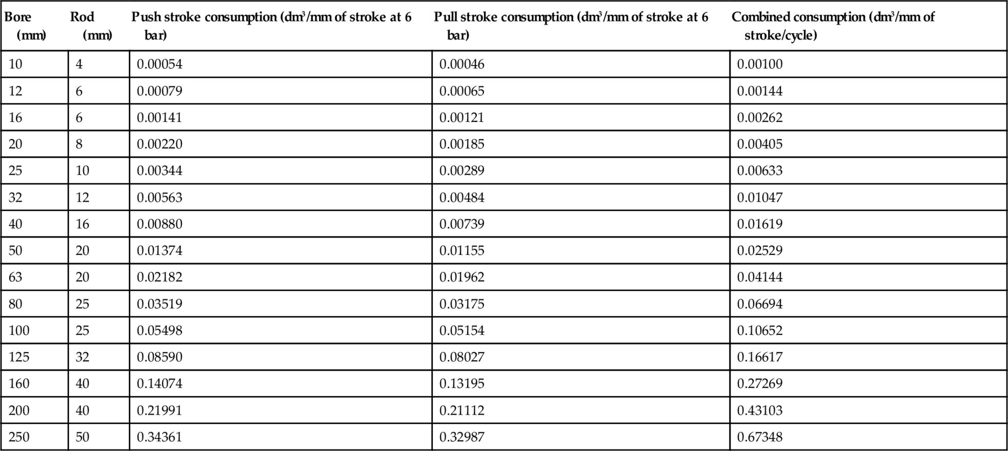
Table of thrust and pulls, single-acting cylinders.
Table of thrust and pulls, double-acting cylinders.
| Cylinder bore mm (in.) | Piston rod diameter mm (in.) | Thrust (N at 6 bar) | Pull (N at 6 bar) |
| 8 | 3 | 30 | 25 |
| 10 | 4 | 47 | 39 |
| 12 | 6 | 67 | 50 |
| 16 | 6 | 120 | 103 |
| 20 | 8 | 188 | 158 |
| 25 | 10 | 294 | 246 |
| 32 | 12 | 482 | 414 |
| 40 | 16 | 753 | 633 |
| 44.45 (1.75) | 16 | 931 | 810 |
| 50 | 20 | 1178 | 989 |
| 63 | 20 | 1870 | 1681 |
| 76.2 (3) | 25 | 2736 | 2441 |
| 80 | 25 | 3015 | 2721 |
| 100 | 25 | 4712 | 4418 |
| 125 | 32 | 7363 | 6881 |
| 152.4 (6) | (1½) | 10 944 | 10 260 |
| 160 | 40 | 12 063 | 11 309 |
| 200 | 40 | 18 849 | 18 095 |
| 250 | 50 | 29 452 | 28 274 |
| 304.8 (12) | (2¼) | 43 779 | 42 240 |
| 320 | 63 | 48 254 | 46 384 |
| 355.6 (14) | (2¼) | 59 588 | 58 049 |
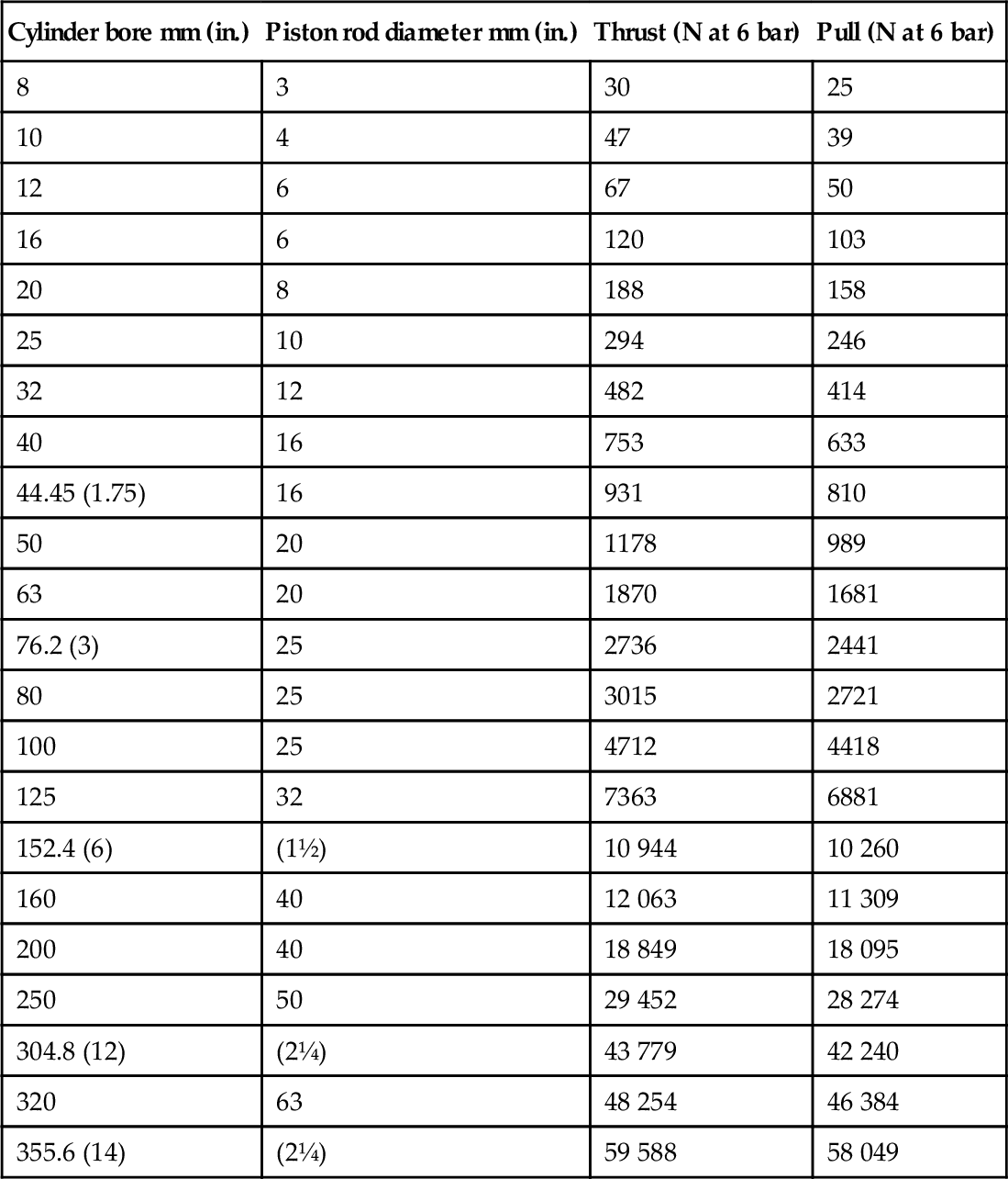
6 bar inlet to the cylinder. For forces at other pressures divide the figures by 6 and multiply by the required pressure in bar gauge.
Load and buckling
For applications with high side loading, use pneumatic slide actuators or standard cylinders fitted with guide units. Alternatively external guide bearings should be installed.
When a long stroke length is specified, care must be taken to ensure the rod length is within the limits for prevention of buckling. The table shows the maximum stroke length for a variety of installation arrangements.
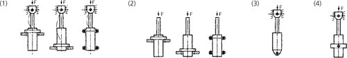
| Cylinder Ø mm (in.) | Piston rod Ø mm (in.) | Load case 1 Pressure (bar) | Load case 2 Pressure (bar) | Load case 3 Pressure (bar) | Load case 4 Pressure (bar) | ||||||||||||
| 4 | 6 | 10 | 16 | 4 | 6 | 10 | 16 | 4 | 6 | 10 | 16 | 4 | 6 | 10 | 16 | ||
| 8 | 3 | 270 | 220 | 170 | 130 | 130 | 100 | 80 | 60 | 170 | 130 | 100 | 80 | 190 | 160 | 120 | 90 |
| 10 | 4 | 380 | 300 | 230 | 170 | 170 | 140 | 100 | 70 | 230 | 180 | 130 | 100 | 260 | 210 | 160 | 120 |
| 12 | 4 | 310 | 250 | 180 | 140 | 140 | 110 | 80 | 50 | 180 | 140 | 100 | 80 | 220 | 170 | 120 | 90 |
| 6 | 730 | 590 | 450 | 350 | 350 | 280 | 210 | 160 | 450 | 360 | 270 | 210 | 520 | 420 | 320 | 240 | |
| 16 | 6 | 540 | 440 | 330 | 250 | 250 | 200 | 150 | 110 | 330 | 260 | 190 | 150 | 380 | 300 | 230 | 240 |
| 8 | 980 | 790 | 600 | 470 | 470 | 370 | 280 | 210 | 600 | 480 | 360 | 280 | 700 | 560 | 430 | 330 | |
| 20 | 8 | 780 | 620 | 470 | 370 | 370 | 290 | 220 | 160 | 470 | 380 | 280 | 210 | 550 | 440 | 330 | 250 |
| 10 | 1200 | 1000 | 760 | 590 | 590 | 470 | 350 | 270 | 760 | 610 | 460 | 350 | 880 | 710 | 540 | 410 | |
| 25 | 10 | 970 | 790 | 600 | 460 | 460 | 370 | 270 | 200 | 600 | 480 | 360 | 270 | 690 | 560 | 420 | 320 |
| 12 | 1400 | 1100 | 880 | 680 | 680 | 550 | 410 | 310 | 870 | 700 | 530 | 410 | 1000 | 820 | 620 | 480 | |
| 31.75 (1.25) | 12 | 1100 | 890 | 680 | 520 | 520 | 420 | 310 | 230 | 680 | 540 | 410 | 310 | 790 | 630 | 480 | 360 |
| 32 | 12 | 1100 | 860 | 650 | 500 | 500 | 390 | 290 | 210 | 650 | 520 | 380 | 290 | 760 | 600 | 450 | 340 |
| 16 | 2000 | 1600 | 1200 | 960 | 960 | 770 | 580 | 450 | 1200 | 990 | 750 | 580 | 1400 | 1100 | 870 | 680 | |
| 40 | 14 | 1200 | 960 | 730 | 570 | 570 | 450 | 340 | 250 | 730 | 580 | 440 | 330 | 850 | 680 | 510 | 390 |
| 16 | 1600 | 1200 | 950 | 730 | 730 | 580 | 430 | 320 | 940 | 750 | 560 | 430 | 1100 | 880 | 660 | 500 | |
| 44.45 (1.75) | 16 | 1400 | 1100 | 870 | 670 | 670 | 540 | 400 | 300 | 860 | 690 | 520 | 400 | 1000 | 810 | 610 | 470 |
| 50 | 20 | 2000 | 1600 | 1200 | 930 | 930 | 740 | 550 | 420 | 1200 | 960 | 720 | 550 | 1400 | 1100 | 840 | 640 |
| 50.8(2) | 20 | 1900 | 1600 | 1200 | 930 | 930 | 740 | 550 | 420 | 1200 | 960 | 720 | 550 | 1400 | 1100 | 840 | 640 |
| 63 | 20 | 1500 | 1200 | 930 | 720 | 720 | 570 | 420 | 310 | 930 | 740 | 550 | 420 | 1100 | 860 | 650 | 490 |
| 63.5 (2.5) | 25 | 2400 | 2000 | 1500 | 1200 | 1200 | 930 | 700 | 530 | 1500 | 1200 | 900 | 690 | 1700 | 1400 | 1100 | 810 |
| 76.2 (3) | 25 | 2000 | 1600 | 1200 | 950 | 950 | 760 | 560 | 420 | 1200 | 980 | 740 | 560 | 1400 | 1100 | 860 | 660 |
| 80 | 25 | 1900 | 1500 | 1100 | 880 | 880 | 700 | 510 | 380 | 1100 | 910 | 680 | 510 | 1300 | 1100 | 800 | 600 |
| 100 | 25 | 1500 | 1200 | 880 | 670 | 670 | 520 | 380 | 270 | 880 | 690 | 510 | 370 | 1000 | 820 | 600 | 450 |
| 101.6(4) | 32 | 2400 | 2000 | 1500 | 1100 | 1100 | 910 | 670 | 500 | 1500 | 1200 | 890 | 670 | 1700 | 1400 | 1000 | 790 |
| 125 | 32 | 2000 | 1600 | 1200 | 910 | 910 | 710 | 520 | 380 | 1200 | 940 | 690 | 520 | 1400 | 1100 | 820 | 620 |
| 127(5) | 38.1 (1.5) | 2800 | 2200 | 1700 | 1300 | 1300 | 1000 | 760 | 570 | 1700 | 1300 | 1000 | 760 | 2000 | 1600 | 1200 | 900 |
| 152.4 (6) | 38.1 (1.5) | 2300 | 1800 | 1400 | 1100 | 1100 | 830 | 610 | 440 | 1400 | 1100 | 810 | 600 | 1600 | 1300 | 950 | 720 |
| 160 | 40 | 2400 | 1900 | 1500 | 1100 | 1100 | 880 | 640 | 480 | 1400 | 1200 | 860 | 640 | 1700 | 1400 | 1000 | 760 |
| 200 | 40 | 1900 | 1500 | 1100 | 860 | 860 | 670 | 480 | 350 | 1100 | 890 | 650 | 480 | 1300 | 1000 | 770 | 580 |
| 203.2 (8) | 44.45 (1.75) | 2300 | 1900 | 1400 | 1100 | 1100 | 840 | 610 | 440 | 1400 | 1100 | 810 | 600 | 1600 | 1300 | 960 | 720 |
| 250 | 50 | 2400 | 1900 | 1400 | 1100 | 1100 | 850 | 620 | 440 | 1400 | 1100 | 830 | 610 | 1700 | 1300 | 980 | 730 |
| 254 (10) | 57.15 (2.25) | 3100 | 2500 | 1900 | 1400 | 1400 | 1100 | 840 | 620 | 1900 | 1500 | 1100 | 830 | 2200 | 1700 | 1300 | 990 |
| 304.8(12) | 57.15 (2.25) | 2500 | 2000 | 1500 | 1200 | 1200 | 920 | 660 | 480 | 1500 | 1200 | 890 | 660 | 1800 | 1400 | 1100 | 790 |
| 320 | 63 | 3000 | 2400 | 1800 | 1400 | 1400 | 1100 | 780 | 570 | 1800 | 1400 | 1000 | 780 | 2100 | 1700 | 1200 | 930 |
| 355.6 (14) | 57.15 (2.25) | 2100 | 1700 | 1300 | 970 | 970 | 760 | 540 | 380 | 1300 | 1000 | 730 | 540 | 1500 | 1200 | 870 | 650 |

Valve flow
There are a variety of standards and methods for the measurement and display of valve flow performance. These can give rise to confusion and difficulty when comparing the published performance of different valves. The table below provides conversion factors as a guide to expressing valve performance in different units.
Flow factor conversion table
| Factors | Flow† | Orifice Size | |||||
| Cv | Kv | C | m3/h | l/min | A | S | |
| *Cv | 1 | 0.869 | 4.08 | 59.1 | 985 | 16.3 | 21.5 |
| Kv | 1.15 | 1 | 4.69 | 67.9 | 1132 | 18.7 | 24.7 |
| C | 0.245 | 0.213 | 1 | 14.5 | 241 | 4.11 | 5.27 |
| M3/h | 0.017 | 0.015 | 0.069 | 1 | 16.67 | 0.276 | 0.364 |
| l/min | 0.001 | 0.0088 | 0.0041 | 0.06 | 1 | 0.016 | 0.022 |
| A | 0.061 | 0.053 | 0.243 | 3.62 | 60.4 | 1 | 1.31 |
| S | 0.046 | 0.040 | 0.189 | 2.75 | 45.8 | 0.761 | 1 |

Source: IMI Norgen Ltd.
* Flow parameters are 6 bar inlet and 5 bar outlet at 20°C, 1013 mbar and 65% humidity.
† 'Cv’ is specified by ANSI/NFPA.
How to use
Select the unit of measurement that is known in the left hand column and multiply by the factor given in the column of the required unit of measurement:
'Cv’ is specified by ANSI/NFPA.
'Kv’ used in Germany and based on water flow.
'C’ sonic conductance in dm3/s/bar specified by ISO 6358.
'A’ effective area in mm2 specified by ISO 6358.
'S' effective area in mm2 according to the Japanese standard JIS B 8375.
A further measurement is the NW value. This gives the equivalent diameter in mm2 of the smallest path through a valve. This is non-comparable and not in the table.
Lubricants
When to lubricate, via an oil-fog or micro-fog lubricator, is generally explained in this catalogue. However, the oil recommended is very much dependant on the local conditions and not least availability of various brands and labels.
In each country Norgren can recommend equivalent products, based on the information from the suppliers.
5.6.20 Guideline documents
| BFPA/P3 | 1995 | Guidelines for the Safe Application of Hydraulic and Pneumatic Fluid Power Equipment |
| BFPA/P4 | 1986 | Guidelines for the Design of Quieter Hydraulic Fluid Power Systems (Third Edition) |
| BFPA/P5 | 1999 | Guidelines to Contamination Control in Hydraulic Fluid Power Systems |
| BFPA/P22 | 2003 | Guidelines on Selection of Industrial O-Rings (Metric & Inch) |
| BFPA/P27 | 1993 | Guidelines on Understanding the Electrical Characteristics of Solenoids for Fluid Power Control Valves & their Application in Potentially Explosive Atmospheres |
| BFP/P28 | 1994 | Guidelines for Errors and Accuracy of Measurements in the Testing of Hydraulic & Pneumatic Fluid Power Components |
| BFPA/P29 | 1987 | General conditions for the Preparation of Terms and Conditions of Sale of UK Fluid Power Equipment Manufacturers and Suppliers |
| BFPA/P41 | 1995 | Guidelines to Hydraulic Fluid Power Control Components |
| BFPA/P44 | 1995 | Index of BS/ISO Standards Relating to Fluid Power |
| BFPA/P47 | 2004 | Guidelines to the Use of Hydraulic Fluid Power Hose and Hose Assemblies |
| BFPA/P48 | 1998 | Guidelines to the Cleanliness of Hydraulic Fluid Power Components |
| BFPA/P49 | 1995 | Guidelines to Electro-hydraulic Control Systems |
| BFPA/P52 | 1997 | Guidelines to the Plugging of Hydraulic Manifolds and Components |
| BFPA/P53 | 2002 | Fluid Power at the Forefront |
| BFPA/P54 | 2003 | Guidelines to the Pressure System Safety Regulations 2000 and their Application to Gas-loaded Accumulators |
| BFPA/P55 | 1993 | Guidelines for the Comparison of Particle Counters and Counting Systems for the Assessment of Solid Particles in Liquid |
| BFPA/P7 | 2004 | Guidelines to the Design, Installation and Commissioning of Piped Systems Part 1 – Hydraulics |
| BFPA/P9 | 1992 | Guidelines for the Flushing of Hydraulic Systems |
| BFPA/P12 | 1995 | Hydraulic Fluids Mineral Oil Data Sheets |
| BFPA/P56 | 2004 | BFPA Fluid Power, Engineer’s Data Booklet |
| BFPA/P57 | 1993 | Guidelines to the Use of Ecologically Acceptable Hydraulic Fluids in Hydraulic Fluid Power Systems |
| BFPA/P58 | 2003 | The Making of Fluid Power Standards |
| BFPA/P59 | 1993 | Proceedings of the 1993 BFPA Leak-Free Hydraulics Seminar |
| BFPA/P60 | 1994 | Leak-Free for Hydraulic Connections |
| BFPA/P61 | 1998 | A Guide to the Use of CE Mark |
| BFPA/P65 | 1995 | VDMA 24 568 & 24 569 Rapidly Biologically Degradable Hydraulic Fluids Minimum Technical Requirements & Conversion from Fluids based on Mineral Oils |
| BFPA/P66 | 1995 | BFPA Survey on Ecologically Acceptable Hydraulic Fluids |
| BFPA/P67 | 1996 | Ecologically Acceptable Hydraulic Fluids Data Sheets |
| BFPA/P68 | 1995 | Machinery Directive Manufacturers Declarations |
| BFPA/P83 | 2003 | The World of Fluid Power 2003 CD Rom (Edition 3) |
| BFPA/P95 | 2003 | Principles of Hydraulic System Design |
| BFPA/P100 | 2003 | Guidelines for the Proof & Burst Pressure Testing of Fluid Power Components |
| BFPDA/D2 | 1994 | Technical Guidelines for Distributors of Hydraulic Fluid Power Equipment |
| BFPA/P13 | 1996 | Fire-Resistant Hydraulic Fluids Data Sheets |
Available from British fluid power association
Source: Page 27 BFPA hand book.
For further information relating to fluid power transmission equipment the reader is referred to the companies and associations listed in Appendix 3.