
Computer-Aided Engineering
8.1 Computer numerical control
8.1.1 Typical applications of computer numerical control
Computer numerical control (CNC) is applied to a wide range of production processes in many industries. In the engineering industries it is applied to such processes as:
– Milling machines and machining centres
– Centre lathes and turning centres
– Drilling machines
– Precision, grinding machines
– Electro-discharge machining (EDM) (spark erosion) machines
– Die sinking machines
(b) Sheet metal working machines, including
– Riveting machines
– Forming machines
(c) Fabrication equipment, including
– Welding machines
– Tube bending machines
(d) Inspection machines for checking three-dimensionally (3D) contoured components.
8.1.2 Advantages and limitations of CNC
It is evident from the wide and increasing use of computer numerically controlled machines in manufacturing industry that the advantages substantially outweigh the limitations.
Advantages
High productivity Although the cutting speeds and feeds for CNC machines are the same as for manually operated machines, much time is saved by rapid traversing and positioning between operations. Also a wider range of operations is possible on a CNC machine, avoiding the necessity to pass the work from one machine to another for, say, each of drilling, milling and boring. This reduces the need for expensive jigs and fixtures, and avoids reserves of work in progress between operations. In addition, CNC machines do not become tired and they maintain a constant rate of productivity. If the work is robot fed, they can work ‘lights out’ through the night.
Design flexibility Complex shapes are easily produced on CNC machines. In addition, contoured solids can be produced on CNC machines which cannot be produced on conventional, manually operated machines.
Management control Production rates, reduced scrap and improved quality comes under management control with CNC machines and is not influenced by operator performance.
Quality CNC machines have a higher accuracy and better repeatability than conventional machines. If the machine is fitted with adaptive control it will even sense tool failure or other variations in performance and either stop the machine or, if fitted with automatic tool changing, select backup tooling from the tool magazine before scrap is produced or the machine damaged.
Reduced lead time The lead time for CNC machines is much less than for other automatic machines. There are no complex and expensive cams and form tools; it is necessary simply to write a part program and load it into the machine memory. Complex profiles are generated using standard tooling.
Limitations
Capital cost The initial cost of CNC machines is substantially higher than for manually operated machines of the same type. However, in recent years, the cost differential has come down somewhat.
Tooling cost To exploit the production potential of CNC machine tools, specialized cutting tools are required. Although the initial cost is high, this largely reflects the cost of the tool shanks and tool holding devices which do not have to be replaced. The cost of replacement tool tips is no higher than for conventional machines.
Maintenance Due to the complexity of CNC machine tools, few small and medium companies will have the expertise to carry out more than very basic maintenance and repairs. Therefore, maintenance contracts are advisable. These are expensive, approximately 10% of the capital cost per annum.
Training Programmer/operator training is required. This is usually provided by the equipment manufacturer but can be time consuming and costly.
Depreciation As with all computer-based devices, CNC controllers rapidly become obsolescent. Therefore, CNC machines should be amortized over a shorter period than is usual with manually operated machines and should be replaced approximately every 5 years.
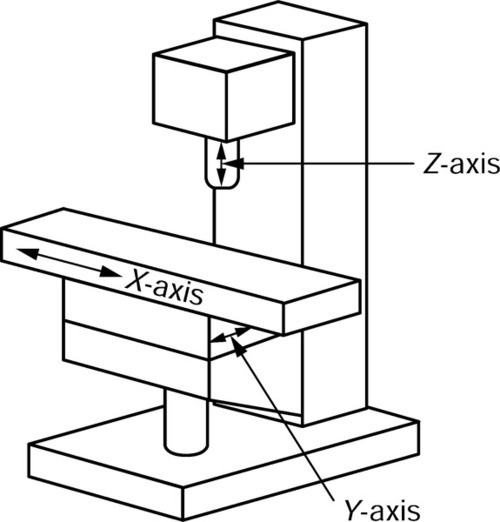
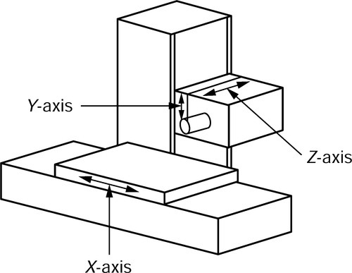
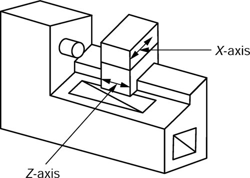
8.1.3 Axes of control for machine tools
There are a number of axis configurations for CNC machine tools; the most common are used with vertical/horizontal milling machines and lathes as shown. Note that:
(a) The Z-axis is always the main spindle axis.
(b) The X-axis is always horizontal and perpendicular to the Z-axis.
(c) The Y-axis is perpendicular to both the X-and Z-axis.
8.1.4 Control systems
Control systems for CNC machine tools broadly fall into two categories as follows.
Open-loop control
This system derives its name from the fact that there is no feedback in the system, and hence no comparison between input and output. The system uses stepper motors to drive the positioning mechanism, and these have only limited torque compared with more conventional servo motors. Further, if the drag of the mechanism causes the motor to stall and miss a step, no corrective action is taken by the system.

Closed-loop control
The following figure explains closed-loop control system:
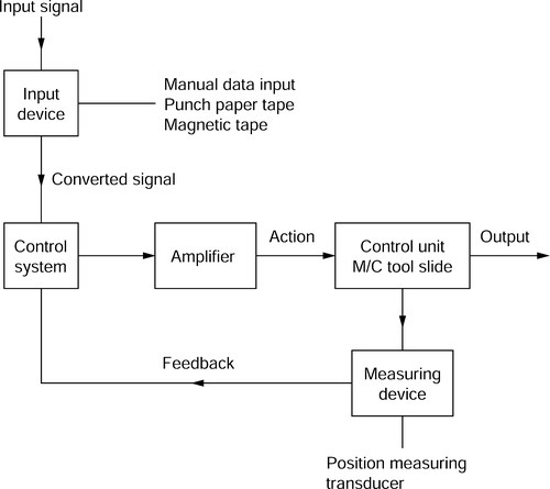
In a closed-loop control system the feedback continuously influences the action of the controller and corrects any positional errors. This system allows the use of servo motors to drive the positioning mechanism, and these have a much higher torque than the stepper motors used with the open-loop control system.
8.1.5 Program terminology and format
Character
A character is a number, letter or other symbol which is recognized by the controller. An associated group of characters makes a word.
Word
A word is a group of characters which defines one complete element of information (e.g. N100). There are two types of word as follows.
Dimensional words
These are any words related to a linear dimension; that is, any word commencing with the characters X, Y, Z, I, J, K or any word in which these characters are inferred.
The letters X, Y, Z refer to dimensions parallel to the corresponding machine axes, as explained in Section 8.1.3.
The letters I, J, K refer to arcs of circles. The start and finish positions of the arcs are defined by X, Y, Z dimensions, whilst the centre of radius of the arc is defined using I, J, K dimensions, with:
I dimensions corresponding to X dimensions
J dimensions corresponding to Y dimensions
K dimensions corresponding to Z dimensions.
Current practice favours the use of the decimal point in specifying dimension words. Thus, a machine manual may stipulate that an X dimension word has the form X4, 3, which means that the X dimension may have up to 4 digits in front of the decimal point and up to 3 digits behind the decimal point. Some older systems, still widely in use, do not use the decimal point but use leading and trailing zeros; for example, 25.4 would be written 0025400.
Management words
These are any words which are not related to a dimension; that is, any word commencing with the characters N, G, F, S, T, M or any word in which the above characters are inferred. Examples of management words may be as follows:
N4 Sequence number: the character N followed by up to four digits (i.e. N1 … N9999).
G2 Preparatory function: the character G followed by up to two digits (i.e. G0 … G99).
F4 Feed rate command: the character F followed by up to four digits.
S4 Spindle speed command: the character S followed by up to four digits.
T2 Tool identifier: the character T followed by up to two digits.
M2 Miscellaneous commands: the character M followed by up to two digits.
Note that N, G, T and M commands may require leading zeros to be programmed on some older but still widely used systems (e.g. G0 would be G00, G1 would be G01, etc.).
8.1.6 Word (or letter) address format
This is, currently, the most widely used format. Each word commences with a letter character called an address. Hence, a word is identified by its letter character and not by its position in the block (in contrast to the fixed block system described below). Thus in a word (or letter) address format, instructions which remain unchanged from a previous block may be omitted from subsequent blocks.
A typical letter address format, as given by a maker’s handbook, could be:

8.1.7 Coded information
A CNC program contains the information for the manufacture of a component part. The CNC controller regulates the signals and sequence to the various drive units.
Codes
| Block numbers | N |
| Preparatory functions | G |
| Dimensional data | X, Y, Z, I, J, K |
| Feed rates | F |
| Spindle speeds | S |
| Tool numbers | T |
| Miscellaneous functions | M |
A sample of a CNC program could look like this:

Block numbers
The block number is usually the first word which appears in any block. Blocks are numbered in steps of 5 or 10 so that additional blocks can be easily inserted in the event of an omission.
Preparatory functions (G)
These are used to inform the machine controller of the functions required for the next operation. Standardized preparatory functions are shown in the following table. In practice, the actual codes used will depend on the control system and the machine type. The codes that one system uses can vary from those of another, so reference to the relevant programming manual is essential.
| Code number | Functiona | |
| G00 | Rapid positioning, point to point | (M) |
| G01 | Positioning at controlled feed rate, normal dimensions | (M) |
| G02 | Circular interpolation, normal dimensions | (M) |
| G03 | Circular interpolation counter clockwise (CCW), normal dimensions | (M) |
| G04 | Dwell for programmed duration | |
| Hold: cancelled by operator | ||
| Reserved for future standardization: not | ||
| normally used | ||
| G08 | Programmed slide acceleration | |
| G09 | Programmed slide deceleration | |
| G10 | Linear interpolation, long dimensions | (M) |
| G11 | Linear interpolation, short dimensions | (M) |
| G12 | 3D interpolation | (M) |
| G13-G16 | Axis selection | (M) |
| G17 | XY plane selection | (M) |
| G18 | ZX plane selection | (M) |
| G19 | YZ plane selection | (M) |
| G20 | Circular interpolation clockwise (CW), long dimensions | (M) |
| G21 | Circular interpolation CW, short dimensions | (M) |
| G22 | Coupled motion positive | |
| G23 | Coupled motion negative | |
| G24 | Reserved for future standardization | |
| G25-G29 | Available for individual use | |
| G30 | Circular interpolation CCW, long dimensions | (M) |
| G31 | Circular interpolation CCW, short dimensions | (M) |
| G32 | Reserved for future standardization | |
| G33 | Thread cutting, constant lead | (M) |
| G34 | Thread cutting, increasing lead | (M) |
| G35 | Thread cutting, decreasing lead | (M) |
| G36-G39 | Available for individual use | |
| G40 | Cutter compensation, cancel | (M) |
| G41 | Cutter compensation, left | (M) |
| G42 | Cutter compensation, right | (M) |
| G43 | Cutter compensation, positive | |
| G44 | Cutter compensation, negative | |
| G45 | Cutter compensation +/+ | |
| G46 | Cutter compensation +/– | |
| G47 | Cutter compensation –/– | |
| G48 | Cutter compensation –/+ | |
| G49 | Cutter compensation 0/+ | |
| G50 | Cutter compensation 0/- | |
| G51 | Cutter compensation +/0 | |
| G52 | Cutter compensation –/0 | |
| G53 | Linear shift cancel | (M) |
| G54 | Linear shift X | (M) |
| G55 | Linear shift Y | (M) |
| G56 | Linear shift Z | (M) |
| G57 | Linear shift XY | (M) |
| G58 | Linear shift XZ | (M) |
| G59 | Linear shift YZ | (M) |
| G60 | Positioning exact 1 | (M) |
| G61 | Positioning exact 2 | (M) |
| G62 | Positioning fast | (M) |
| G63 | Tapping | |
| G64 | Change of rate | |
| G65-G79 | Reserved for future standardization | |
| G80 | Fixed cycle cancel | (M) |
| G81-G89 | Fixed cycles | (M) |
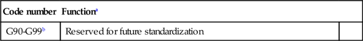
| G90-G99b | Reserved for future standardization |
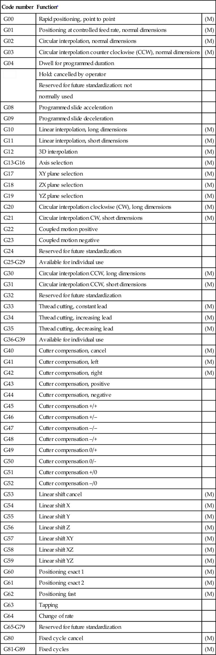
(M)indicates modal G commands which remain in force from line to line until cancelled.
a Variations on standard codings occur not only between the different makes of controller but between different models by the same maker and even between different types of the same model. Thus again it must be stressed that the programmer/operator must work from the manufacturer’s manual for a given machine/controller combination.
b Most control units use G90 to establish the program in absolute dimensional units, and G91 to establish the program in incremental dimensional units, however. FANUC control units use G20 in place of G90, and G21 in place of G92.
Dimensional words
A CNC machine tool will have axes which are addressed by letters (X, Y, Z, etc.). The CNC program will instruct the controller to drive the appropriate machine elements to a required position parallel to the relevant axes using dimensional words (X25.0 Y55.0) which consists of the axis letter plus a dimension. These dimensional words are sign sensitive (— or +). If there is no sign, the number is assumed positive by the controller. This adds built-in safety to a CNC program, ensuring that should a CNC programmer fail to input a minus value to a Z-axis command the tool should move to ’safe’ as shown below. That is, it moves away from the workpiece, as shown in the following figure.
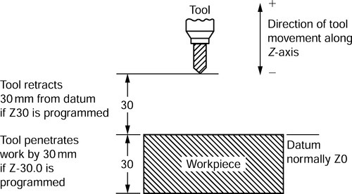
Consider a line of program N10 G01 X25.0 Y25.0 Z30.0. This would result in the tool moving to the coordinates X25, Y25, Z30. However, since the Z word is positive the tool will go up and not down 30mm from the datum. To drill the component to a depth of 30 mm the line of program should read N10 G01 X25.0 Y25.0 Z-30.0.
Feed rate (F)
Words commencing with F indicate to the controller the desired feed rate for machining. There are a number of ways of defining the feed rate:
(a) Millimetres/minute: F30 = 30mm/min.
(b) Millimetres/revolution: F0.2 = 0.2 mm/rev.
(c) Feed rate number 1–20 indicates feed rates predetermined by the manufacture in rev/min or mm/min as appropriate. To use this system the feed rate command is prefaced by a G code. Only a few older machines use this system.
Spindle speed (S)
Words commencing with the letter S indicate to the controller the desired spindle speed for machining. Once again there are a number of ways of defining the spindle speed, each selected by use of the appropriate G code:
(a) Spindle speed in revolutions/minute (r.p.m.).
(b) Cutting speed in metres/minute.
(c) Constant cutting speed in metres/minute.
Tool numbers (T)
Each tool used during the machining of a part will have its own number (e.g. T01 for tool 1, T19 for tool 19). Most CNC machine controllers can hold information about 20 tools or more. This tool information will take the form of a tool length offset (TLO) and a tool diameter/radius compensation (see Sections 8.1.9 and 8.1.10). Where the machine is fitted with automatic tool changing it will also identify the position of the tool in the tool magazine.
Miscellaneous functions (M)
Apart from preparatory functions there are a number of other functions that are required throughout the program (e.g. ’switch spindle on’, ’switch coolant on’, etc). These functions have been standardized and are popularly known as M codes. The address letter M is followed by two digits. The most commonly used M codes are as follows:
8.1.8 Data input
Program data can be entered into a CNC machine by a number of methods:
Manual data input (MDI) This method requires data input by an operator key boarding in the data to a tape punch (now obsolescent).
Magnetic tape This requires the CNC program to be ‘copied’ to a magnetic tape or cartridge (now obsolescent).
Computer aided programming Programming on a computer using software that not only generates the program but simulates its operation to test its accuracy and safety before up-loading it into the machine control unit.
Direct numerical control (DNC) This requires the prepared CNC program to be stored in the memory of a remote computer. The CNC data is then transferred directly down line to the CNC machine tool by means of a suitable communications link.
Conversational data input This enables the operator to load the program directly into the machine control unit by responding to ‘prompts’ & ‘menus’ appearing on the control unit screen. The controller has a split memory so that a previous program can continue operating the machine whilst a new program is being loaded.
8.1.9 Tool length offsets: milling
Most machining operations require the use of a number of tools, which vary in length and diameter. In order to allow for these variables, TLO and tool diameter compensation facilities can be used.
TLO allow for a number of tools with varying length to be programmed to a common datum or zero, as shown in the figure.

8.1.10 Cutter diameter compensation: milling
When using diameter or radius compensation, normal practice would be to program for the actual size of the component and then use the diameter compensation facility to allow for the radius of the cutter. Another use of this feature allows for the changing of tools of different diameters, without altering the CNC part program. Diameter compensation is activated by the following preparatory codes (see Section 8.1.7):
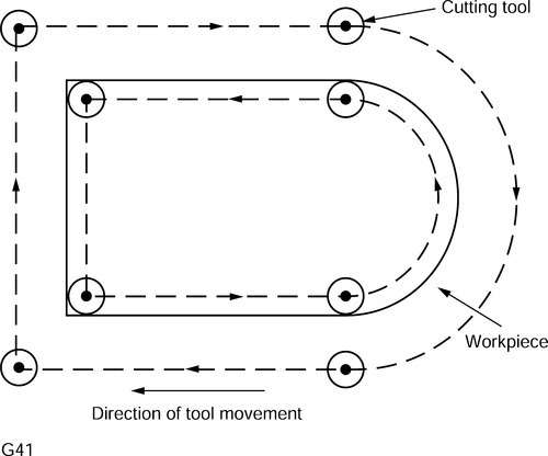
G41 Compensation to the left
The cutter is always to the left of the surface being machined when looking along the path of the cutter, as indicated by the arrows in the figure.
G42 Compensation to the right
The cutter is always to the right of the surface being machined when looking along the path of the cutter, as indicated by the arrows in the figure.

G40 Turning compensation on and off
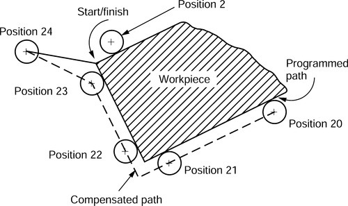
Whenever G41 or G42 is activated, the cutter diameter is compensated during the next move in the X and Y axes, as shown. The preliminary movement of the cutter before cutting commences is called ramping on.
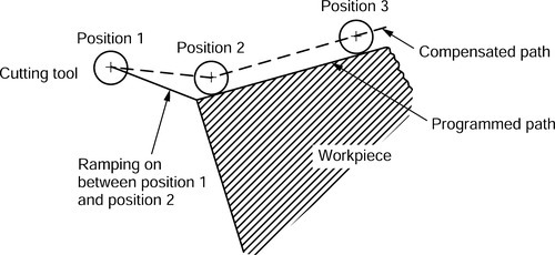
Similarly G40 causes the compensation to be cancelled on the next X and Y movements as shown, and is known as ramping off.
Ramping on and ramping off allow the feed servo motor to accelerate to the required feed rate, and to decelerate at the end of the cut whilst the cutter is clear of the work. It therefore follows that diameter compensation can never be applied or cancelled when the cutting tool is in direct contact with the workpiece.
8.1.11 Programming techniques: milling and drilling
Canned cycles
To save repetitive programming on similar operations, CNC controllers offer a range of canned or fixed cycles. It is only necessary to provide dimensional data with the required G code. Some examples of canned cycles for milling are as follows:
G81 Drilling cycle
One of the most popular canned cycles is the drilling cycle G81. The machine movements involved in drilling a series of holes are shown and are as follows:
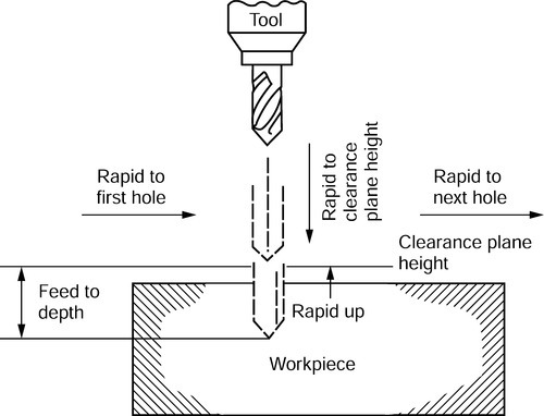
(a) Rapid to centre of first hole.
(b) Rapid to clearance plane height.
(c) Feed to depth of hole.
(d) Rapid up to clearance plane height.
(e) Rapid to centre of next hole.
(f) Repeat for as many holes as required.
The only data which needs to be programmed is:
Hole position (X, Y)
Hole depth (Z)
Spindle speed (S)
Feed rate (F).
8.1.12 Programming example: milling
Component
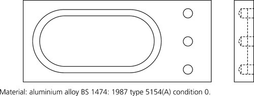
Material: aluminium alloy BS 1474: 1987 type 5154(A) condition 0.
Machining data
| Tool no. | Tool description | Spindle speeds (rev/min) | Feed rates (mm/min) | |
| Vertical | Horizontal | |||
| T01 | 10 mm diameter slot drill | 1500 | 70 | 100 |
| T02 | No. 2 centre drill | 2500 | 40 | – |
| T03 | 8 mm diameter twist drill | 1760 | 60 | – |

The tool change position will be X — 100.0, Y — 100.0. The appropriate M code in the program for tool changing will move the tool to these coordinates and retract the tool up the Z-axis to a ‘home’ position clear of the work to facilitate manual tool change.
Centre line path/point programming will be used, and to avoid complexity no diameter compensation will be shown in this example.
Dimensional data
The dimensions shown provide the X, Y, Z data for the 10mm wide and 8mm deep slot, and the 8 mm diameter and 12 mm deep holes. The numbers in the circles refer to the tool positions as described in the specimen program to follow. The Z datum (Z0) would be the top face of the workpiece.

Specimen program
The format of the following program example would be suitable for the Bridgeport BOSS 6 software. When evaluating the program, reference should be made to the coded information given in Section 8.1.7.
| CNC listing | Description |
| % | Per cent symbol = start of program/tape. |
| N5 G90 G71 G00 G75 | Set up default preparatory codes. G75 is special to BOSS 6 software. |
| N10 X – 100.0 Y – 100.0 S1500 | Rapid move to tool change (home) position. Set spindle speed |
| T01 M06 | (rev/min). Select tool required and insert first tool (slot drill). Stop control for tool change. |
| N15 X50.0 Y30.0 | Restart control. Rapid move to position 1. |
| N20 Z1.0 M03 | Rapid tool move to 1.0mm above workpiece. Start up spindle (speed set in block N10). |
| N25 G01 Z – 8.0 F70 M07 | Linear feed rate move to required depth (70 mm/min). Mist coolant on. |
| N30 G02 X50.0 Y90.0 150.0 | Circular interpolation to X and Y coordinates at position 2, using |
| J60.0 F100 | I and J coordinates for interpolation centers. Increase feed rate (horizontal) to 100mm/min. |
| N35 G01 X100.0 Y90.0 | Linear feed rate move as set in block N30 to position 3. |
| N40 G02 X100.0 Y30.0 | Circular interpolation to X and Y coordinates at position 4 at feed |
| 100.0 J60.0 | rate set in block N30. |
| N45 G01 X50.0 Y30.0 | Linear feed rate move as set in block N30 to position 1. |
| N50 G00 Z1.0 | Rapid move tool clear of workpiece along Z-axis. |
| N55 X – 100.0 Y – 100.0 S2500 | Rapid move to tool change (home) position and stop spindle. |
| T02 M06 | Remove tool 1 and insert tool 2 (center drill). Set spindle speed to 2500 rev/min ready for drilling. |
| N60 X170.0 Y90.0 | Restart control. Rapid move to position 5. |
| N65 Z1.0 M03 | Rapid move to 1.0 mm above workpiece. Start up spindle (speed set to 2500rev/min in block N55). |
| N70 G81 X170.0 Y90.0 Z – 5.0 | Start drilling cycle (see Section 8.1.11) and centre drill first hole |
| F40 M07 | (position 5) to depth at 40mm/min feed rate. Mist coolant on. |
| N75 X170.0 Y60.0 | C/drill second hole (position 6). |
| N80 X170.0 Y30.0 | C/drill third hole (position 7). |
| N85 G80 | Cancel drilling cycle. |
| N90 G00 – X100.0 Y – 100.0 | Rapid move to tool change (home) position and stop spindle. |
| S1760 T03 M06 | Remove tool 2. Insert tool 3 (twist drill). Set spindle speed to 1760 rev/min ready for drilling. |
| N95 X170.0 Y90.0 | Rapid move to position 5. |
| N100 Z1.0 M03 | Rapid move tool to 1 mm above workpiece. Start spindle. |
| N105 G81 X170.0 Y90.0 Z – | Start drilling cycle and drill first hole to depth (12 mm) at position |
| 12.0 F60 M07 | 5 with 60 mm/min feed rate. Mist coolant on. |
| N110 X170.0 Y60.0 | Drill second hole (position 6). |
| N115 X170.0 Y30.0 | Drill third hole (position 7). |
| N120 G80 | Turn spindle off. |
| N125 G00 X – 100.0 Y – | Return tool to tool change (home) position and stop spindle. |
| 100.0 M06 | Ready for repeat of program. |
| N130 M02 | End or program. |
| N135 M30 | End of tape. |
8.1.13 Tool offsets: lathe
On a CNC lathe, to keep a common datum with all the tools on the turret, TLO are required in both the X- and Z-axis as shown.
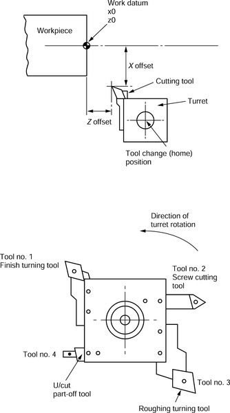
On a CNC centre lathe the turret will hold a number of different tools. Each tool will have its own X and Z offset, which will become operative when the tool is called into the program. When the turret is indexed all the tools will take up a different position relative to the workpiece. As can be seen in the diagram, since the various tools protrude from the turret by different distances in terms of X and Z, different TLO will need to be set for each tool.
8.1.14 Tool nose radius compensation: lathe
Tool nose radius compensation (TNRC) is used in a similar manner to diameter compensation when milling. Consequently the same preparatory codes (G codes) are used to activate and deactivate TNRC. TNRC reduces the complex and repetitive calculations required for tool paths. The programmer can program as if sharp pointed tools were being used. The codes are as follows:
| G41 | Compensates tool nose radius to the left |
| G42 | Compensates tool nose radius to the right |
| G40 | Cancels tool nose radius compensation |
G41 Compensation to the left

G42 Compensation to the right
8.1.15 Programming techniques: lathe
Canned cycles
Examples of some of the canned cycles available when using CNC centre lathe controllers are as follows:
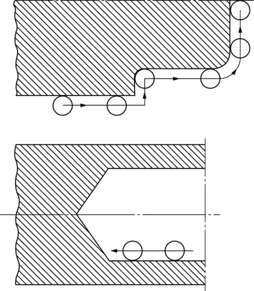
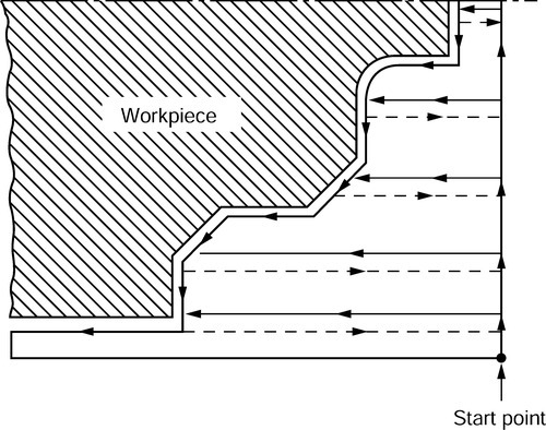
G68 Roughing cycle
This cycle is used for large amounts of stock removal. The cycle is activated by a G68 code. The machine moves are shown and are as follows:
(a) Rapid move to start point.
(b) A number of linear roughing passes (the number varies with depth of cut).
(c) A profiling pass, leaving on a finish allowance.
After the roughing cycle is completed the component would be finish turned to size.
G83 Deep hole drilling cycle
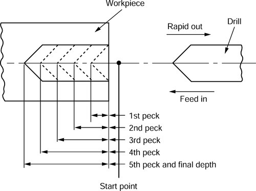
The deep hole drilling cycle is used to drill holes with a high depth/diameter ratio, and provides ‘flute clearance’ during the cycle. The cycle is activated by a G83 code. The moves involved are shown and are as follows:
(a) Rapid move to start point.
(b) Feed to first peck depth.
(c) Rapid move out to start point.
(d) Rapid in just short of first peck.
(e) Feed to second peck depth.
(f) Repeat movements (c)-(e) for each successive peck depth until required depth is achieved.
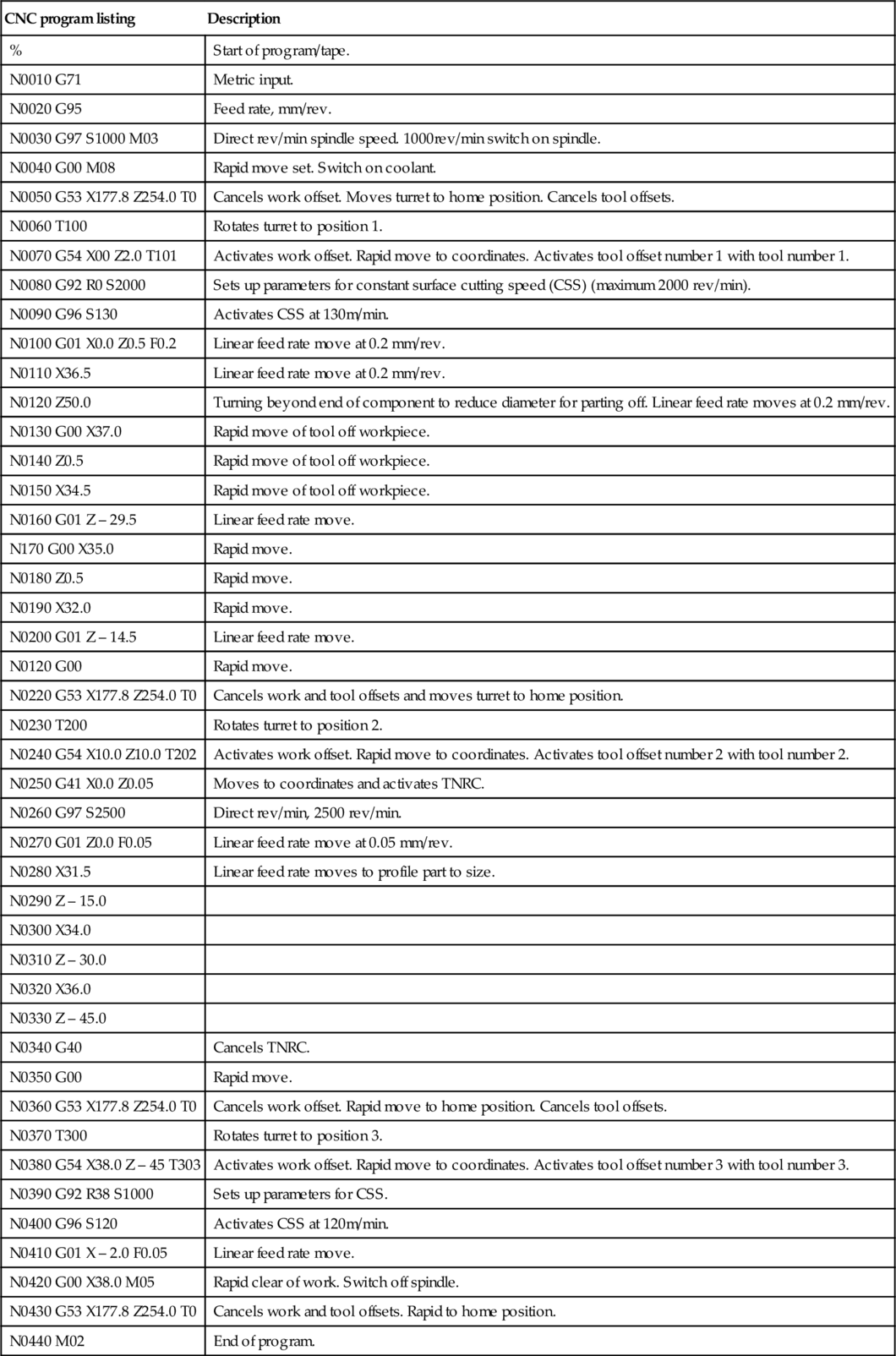
8.1.16 Programming example: lathe
An example CNC program follows. The program is to:
(a) Rough turn leaving 0.5 mm on diameters and faces
(b) Finish turn the part to size
(c) Part off to length.
Component
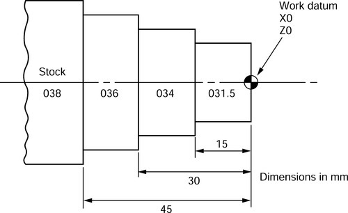
Material: aluminium alloy BS 1474: 1987 type 5154(A) condition 0.
Tool and machining data

Specimen program
(a) The format of the program would be suitable for a GE 1050 CNC controller.
(b) Diameter programming is used in this example.
(c) Tool change position (home position) is X177.8 Z254.
| CNC program listing | Description |
| % | Start of program/tape. |
| N0010 G71 | Metric input. |
| N0020 G95 | Feed rate, mm/rev. |
| N0030 G97 S1000 M03 | Direct rev/min spindle speed. 1000rev/min switch on spindle. |
| N0040 G00 M08 | Rapid move set. Switch on coolant. |
| N0050 G53 X177.8 Z254.0 T0 | Cancels work offset. Moves turret to home position. Cancels tool offsets. |
| N0060 T100 | Rotates turret to position 1. |
| N0070 G54 X00 Z2.0 T101 | Activates work offset. Rapid move to coordinates. Activates tool offset number 1 with tool number 1. |
| N0080 G92 R0 S2000 | Sets up parameters for constant surface cutting speed (CSS) (maximum 2000 rev/min). |
| N0090 G96 S130 | Activates CSS at 130m/min. |
| N0100 G01 X0.0 Z0.5 F0.2 | Linear feed rate move at 0.2 mm/rev. |
| N0110 X36.5 | Linear feed rate move at 0.2 mm/rev. |
| N0120 Z50.0 | Turning beyond end of component to reduce diameter for parting off. Linear feed rate moves at 0.2 mm/rev. |
| N0130 G00 X37.0 | Rapid move of tool off workpiece. |
| N0140 Z0.5 | Rapid move of tool off workpiece. |
| N0150 X34.5 | Rapid move of tool off workpiece. |
| N0160 G01 Z – 29.5 | Linear feed rate move. |
| N170 G00 X35.0 | Rapid move. |
| N0180 Z0.5 | Rapid move. |
| N0190 X32.0 | Rapid move. |
| N0200 G01 Z – 14.5 | Linear feed rate move. |
| N0120 G00 | Rapid move. |
| N0220 G53 X177.8 Z254.0 T0 | Cancels work and tool offsets and moves turret to home position. |
| N0230 T200 | Rotates turret to position 2. |
| N0240 G54 X10.0 Z10.0 T202 | Activates work offset. Rapid move to coordinates. Activates tool offset number 2 with tool number 2. |
| N0250 G41 X0.0 Z0.05 | Moves to coordinates and activates TNRC. |
| N0260 G97 S2500 | Direct rev/min, 2500 rev/min. |
| N0270 G01 Z0.0 F0.05 | Linear feed rate move at 0.05 mm/rev. |
| N0280 X31.5 | Linear feed rate moves to profile part to size. |
| N0290 Z – 15.0 | |
| N0300 X34.0 | |
| N0310 Z – 30.0 | |
| N0320 X36.0 | |
| N0330 Z – 45.0 | |
| N0340 G40 | Cancels TNRC. |
| N0350 G00 | Rapid move. |
| N0360 G53 X177.8 Z254.0 T0 | Cancels work offset. Rapid move to home position. Cancels tool offsets. |
| N0370 T300 | Rotates turret to position 3. |
| N0380 G54 X38.0 Z – 45 T303 | Activates work offset. Rapid move to coordinates. Activates tool offset number 3 with tool number 3. |
| N0390 G92 R38 S1000 | Sets up parameters for CSS. |
| N0400 G96 S120 | Activates CSS at 120m/min. |
| N0410 G01 X – 2.0 F0.05 | Linear feed rate move. |
| N0420 G00 X38.0 M05 | Rapid clear of work. Switch off spindle. |
| N0430 G53 X177.8 Z254.0 T0 | Cancels work and tool offsets. Rapid to home position. |
| N0440 M02 | End of program. |
8.1.17 Glossary of terms
Absolute programming A system of programming where all positional dimensions are related to a common datum.
Adaptive control A system of sensors which changes speeds/feeds in response to changes in cutting loads. Also provides for in-process gauging and size correction.
Address In programming, a symbol which indicates the significance of the information immediately following that symbol.
Backlash 'Wasted’ movements between interacting mechanical parts due to wear and/or manufacturing tolerance.
Binary coded decimal A method of representing decimal numbers by a series of binary numbers.
Binary number A number system with a base of 2.
Bit An abbreviation of ‘binary digit’.
Block A line or group of words which contains all the instructions for one operation.
Byte A group of 8 bits.
CAM Computer-aided manufacture.
Canned cycle An operation which has been preprogrammed and which can be called up by a single instruction.
Circular interpolation A type of contouring control which uses the information contained in a single instruction to produce movement along the arc of a circle.
CLF Cutter location file.
Closed-loop control A system in which a signal depending on the output is fed back to a comparing device so that the output can be compared with the input, and a corrective signal generated if necessary.
Continuous path system A system in which the tool path results from the coordinated simultaneous motion of the work and/or cutter along two or more axes.
Cutter compensation An adjustment which compensates for the difference between the actual and programmed cutter diameters. See also Tool length offset (TLO).
Datum The reference position from which all absolute coordinates are taken.
DNC Direct numerical control.
DO loop A loop back to a repeated instruction in a program.
Encoder A device which is used to convert the position of a moving device into an electronic signal.
Feed rate The rate at which the cutting tool is advanced into the workpiece.
Incremental system A system by which each positional dimension is measured from the preceding position.
In-process gauging A system of gauging built into the machine which gauges the work whilst it is being manufacture so that any errors due to tool wear can be compensated for automatically. In the event of tool failure the machine will automatically change to back-up tooling. Thus the machine can be used unattended in a ‘lightsout’ environment. Used in conjunction with adaptive control.
Interpolation The joining up of programmed points to make a smooth curve by computation.
Linear path system A point-to-point system in which the tool or work moves only in straight lines.
Manual data input (MDI) A means of manually entering instructions to a controller, usually via a key panel.
Numerical control Control of machine movements by the direct insertion of numerical data.
Open-loop system A system where there is a single forward path between the input instruction and the output signal with no feedback.
Parallel path system A point-to-point system in which the tool or work moves only in straight lines parallel to any axis.
Parity A checking method to help determine if the tape has been prepared correctly. The standard for even parity is that of the International Standards Organization (ISO), whereas the standard for odd parity is that of the Electronic Industries Association (EIA).
Part program A program in machine control language and format required to accomplish a given task.
Point-to-point A system in which the controlled motion is required only to reach a given end point, with no path control during the movements from one point to the next.
Post-processor A set of computer instructions which transforms tool centre line data into machine movement commands using the tape code and format required by a specific machine tool control system.
Rapid traverse Movements at a high traverse rate, normally used to save time when positioning the cutter before cutting commences.
Servo system An automatic control system, incorporating power amplification and feedback, designed to make a machine table follow the programmed route.
Spindle speed The rotational speed of the cutting tool or workpiece.
Subroutine A sequence of instructions or statements used to perform an operation which is frequently required. It is prepared by the part programmer and temporarily stored in the controller memory.
Tape punch A device for transferring instructions to a punched tape by perforating it with holes.
Tape reader A device for sensing and transmitting the instructions recorded on a punched or magnetic tape.
Tool length offset (TLO) An instruction which adjusts the position of the spindle along the Z-axis of a milling machine to take account of different lengths of cutting tool. On a lathe, offset is parallel to both the X- and Z-axis.
Word A set of characters which give a single complete instruction to a machine’s control system.
Word address A block of characters preceded by a literal symbol to identify them.
8.2 Computer-aided design
8.2.1 An introduction to computer-aided design
Computer-aided design (CAD) is the application of a computer system which can be used to solve or enhance the solution of design and draughting problems. It not only eases the work of the draughtsperson in preparing drawings in both 2D and 3D, but it can be extended to provide:
• Geometric modelling: wire frame and solid modelling.
• Finite element analysis techniques to solve thermal and mechanical stress problems.
• Testing.
• Documentation.
• CNC programming.
For the architect and civil engineer, the ability to draw not only individual buildings but whole estates and complexes in 3D and then change the viewpoint at the touch of a button is of inestimable value. The use of virtual reality techniques enables the designer to ‘walk through’ an estate or complex.
By far the most widely used application of CAD in small- and medium-engineering companies is as a draughting aid. The capabilities of a typical draughting system could be:
• The production of ‘library symbols’ such as BS 308 conventions, pneumatic symbols, hydraulic symbols, electrical symbols and electronic symbols.
• The production of three view orthographical drawings using these symbols, to avoid having to repeatedly draw small details (e.g. screwed fastenings).
• The automatic production of isometric an oblique drawings from orthographical drawings and the ability to change the viewpoint at will.
• Drawing can be speeded up by such commands as: mirror imaging, rotation, copying, move, zoom, scaling, fillets, rectangles and polygons.
• The automatic shading or hatching of section drawings.
• The facility to make major or minor changes to a drawing without redrawing.
• The production of printed circuit board (PCB) layouts.
• The production of plant layouts.
• The production of parts lists, bills of materials, etc., directly from the digitized drawing data.
• Ease of storage on floppy disks.
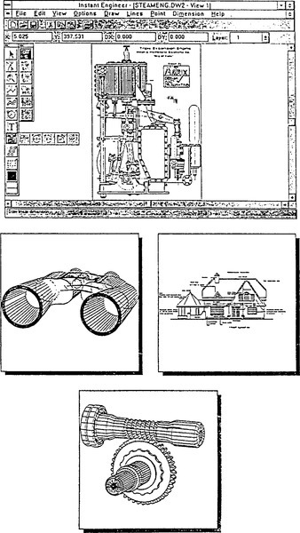
Some typical examples of drawings are shown below. These were produced on DesignCAD and are reproduced by courtesy of PM.S (Instruments) Ltd.
8.2.2 CAD system hardware
Stand-alone work stations
Since the first edition of this pocket book was published, the power of desktop computers has increased out of all recognition and it is now possible to run full-scale CAD packages on such machines.
Centralized processing
Here, one computer (normally a mainframe) supports a number of terminals. Response times can be slower than for ’stand-alone’ systems, particularly if the system is heavily loaded. A schematic of a centralized system is shown below.

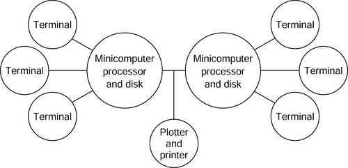
Shared centralized processing
This configuration is more costly than centralized processing since more than one central computer is used at the same time. It has two major advantages. Firstly the response time is improved and, secondly, if one computer fails the system is not totally disabled. A schematic of a shared centralized system is shown below.
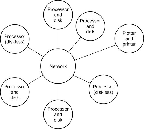
Integrated system
With this configuration, a number of computers are networked together so that the system files can be shared. This arrangement also allows the plotter, printers and disk drives required to become a shared resource, resulting in more economical loading of the system, faster response time and less chance of total disablement. The initial capital outlay is lower, as the system can be started up with only a few workstations. Additional workstations can then be added to the network as and when required. A schematic of an integrated system is shown below.
Visual display units
Nowadays these have to be colour monitors since modern CAD packages have ‘layering’ facilities. For example, an architect can produce the ground floor plan of a building in one colour, and superimpose the first floor plan in another colour to ensure structural integrity. The plumbing and central heating layout can then be superimposed in another colour an the electrical installation in yet another colour to make sure that everything is in the correct place. The layers can then be printed individually or in combination as required.
When producing orthographical engineering drawings it is useful to use one colour layer for the construction lines an another colour layer for the final outline.
When producing PCB layouts, one colour can be used for the tracks on the top of the board and another colour layer for the tracks on the underside of the board.
Colour presentations are also used when producing publicity material, charts and graphs for inclusion in reports, also for overhead projector transparencies.
Input devices
Keyboards These are familiar to all computer operators and are user friendly. These are used to input commands, text and parameter values.
Digitizer tablet The data tablet detects the position of a mechanical scanning or handheld cursor. The tablet contains an electromagnetic, electrostatic or electroresistive grid which corresponds to the resolution of the visual display unit (VDU). Thus, X and Y coordinates on the tablet can be mapped directly on to the screen.
Joystick This is a two-axes control for providing a rapid movement of the cursor. It is familiar to players of video games. When used with CAD systems it allows more rapid cursor movement than is possible from the keyboard. However, the positional accuracy is low and is dependent on operator skill.
Mouse The mouse is now widely used in place of the joystick and is essential when using Windows versions of CAD software. The ‘click’ keys on the mouse allow the command to be entered quickly and easily once the cursor has been positioned.
Output devices
Hard copy can be printed from digitized data in a number of ways.
Flat bed plotter The paper is held to the flat bed of the machine by suction. The pen moves along the X- and Y-axis to draw the image. The carriage moves along the X-axis and the penhead moves along the Y-axis bridge which is located on the carriage. There is also a ‘home’ position to which the penhead is parked at the start and finish of the drawing. This allows the paper to be inserted and the finished drawing removed without fouling the pen. The penhead also returns to the ‘home’ position when the pen has to be changed to accommodate a different line thickness and/or colour. The pens are located in a magazine and are selected on command from the computer.
Drum or roller bed plotter The bed rotates to provide the X-axis movement and the pen carriage moves along the Y-axis parallel to the drum axis of rotation. This arrangement allows large drawings to be produced, yet little floor space is required. These plotters are not quite so accurate as flat bed plotters due to paper stretch and slip. They are also more limited in the range of materials that they will accept.
For small-scale drawings, conventional dot matrix, laser jet and electrostatic printers as used for normal text hard copy printing are suitable.
8.2.3 CAD system software
There are now many CAD packages available. These may be in 2D or 3D. Generally, a 2D package will do anything that can be done manually using a drawing board and T-square together with conventional drawing instruments. You can also produce isometric and oblique ‘pictorial’ representations. To save time it is possible to purchase ‘libraries’ of standard symbols. Some companies provide library information of their products on disk for their customers to use. For example, manufacturers of bathroom and kitchen fittings provide scale drawings of their product range on disk for architects to import directly into their designs. Some users will build up their own libraries of frequently used components using ‘block’ commands.
3D software is necessary when you require:
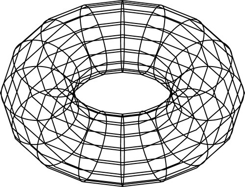
• Wire frame modelling This described the corners and edges of a model as shown below. It can lead to a view looking ambiguous.
• Surface models These are usually used when components have a complex surface, such as a car or an aircraft panel. Information relating to the surface can be extracted from the shaded surface model.
• Solid models These provide detailed information concerning areas, volumes and centre of gravity of a component part. Solid models can be built up from standard 3D shapes and modified to get the desired result.
All CAD software in current use is configured to run in a Windows environment but some versions are available for use with Mackintosh computers. There is a wide range of software packages available configured for use by engineering designers, architects, interior designers, nautical architects and others. They invariably have provision for customising by the user to suit specific applications and are supported by ‘libraries’ of data and symbols that can be selected as required. Although requiring massive computer power compared with earlier versions, the latest, modern desk-top and lap-top computers can still support most of the packages in common use.
8.2.4 Computer-aided design and manufacture
The integration of CAD with computer-aided manufacture (CAM) involves the sharing of a database between these distinct elements. The advantages of such a system are:
• There is consistent reliability of information relating to design and manufacture without the possibility of copying errors.
• CNC programmes can be constructed directly from the digitized data of the drawing in much shorter times.
• Complex parts are programmed without the need for lengthy calculations.
• On-screen proofing of CNC program tool paths reduces the possibility of scrapped components and damaged cutting tools.
• The reduction of lead time between the design stage and the completion of manufacture.
8.2.5 Advantages and limitations of CAD
Advantages
• There are substantial improvements in productivity during the design and draughting process.
• Drawings can be produced to very high levels of accuracy and consistent house styles.
• Product design can be improved.
• It is easy to make modifications without completely redrawing.
• The storing of digitized data on disk is simple and storage space is reduced compared with tracings.
• Colour coded hard copy can be produced whereas conventional dyeline prints are monochrome.
• Digitized data can be used for: costing and estimating, purchasing, production planning and control, control of labour costs, quality control.
• Digitized CAD data can be integrated with CNC machines (CAD/CAM) and also with robots to provide flexible manufacturing systems (FMS).
Limitations
• Hardware and software costs for CAD can be very high. Although the cost of individual components may be reduced, the continual increase in the complexity and sophistication of the software demands greater and greater memory capacity and greater power and speed from the CPU. This overtakes any cost reductions in individual components.
• Powerful CAD systems require regular maintenance, although they are becoming very much more reliable and maintenance contracts are available.
• Initial set-up and staff training can be expensive whilst libraries of conventions an symbols are prepared and digitized to suit company products.
• A suitable ergonomic environment is required to avoid operator fatigue and ensure economic use of the system.
8.3 Industrial robots
8.3.1 An introduction to robotics
An industrial robot is a general purpose, programmable machine possessing certain anthropomorphic (human-like) characteristics. The most typical anthropomorphic characteristic of a robot is its arm. This arm, together with the robot’s capability to be programmed, makes it ideally suited to a variety of production tasks, including machine loading, spot welding, spray painting and assembly. The robot can be programmed to perform a sequence of mechanical motions, and it can repeat that motion sequence indefinitely until reprogrammed to perform some other job.
Manufacturers use robots mostly to reduce manning levels. Robots, used either with other robots or with other machines, have two major advantages compared with traditional machines. First, they allow almost total automation of production processes, leading to increased rates of production better quality control and an increased response to varying demand. Second, they permit the adaptability, at speed, of the production unit. The production line can be switched rapidly from one product to another similar product, for example from one model of car to another. Again, when a breakdown immobilizes one element in the production unit, that element’s function can be replaced quickly.
Adaptable production units are known as FMS. A flexible unit would comprise a small number of robots and computer-controlled machine tools working together to produce or part-produce a particular component or assembly. The logical development of such systems is to integrate a number of these flexible cells into a fully automated workshop or factory.
It must be remembered that the robot, although a highly sophisticated device, cannot by itself solve all the problems that can be solved by the human operator. It must therefore be associated with additional techniques (e.g. CAM).
The term robotics has two currently accepted meanings:
(a) In the strictest sense of the word, it implies the further development of automation by improving the robot as we know it at present.
(b) In the broader sense, it involves the development not only of the robot itself, but also processes associated with the robot (e.g. CAD) or the consideration of the robot as a machine with special properties in association with other machines (e.g. flexible manufacturing cells or systems).
8.3.2 Robot control
An industrial robot shares many attributes in common with a CNC machine tool. The type of technology used to operate CNC machine tools is also used to actuate the robot’s mechanical arm. However, the uses of the robot are more general, typically involving the handling of work parts. Robots can be programmed from a computer on-line or off-line. Alternatively, the robot can be guided through a sequence of movements from a remote key pad coupled to the robot by a trailing lead. Thirdly, the robot can be guided manually through a sequence of movements as when spray painting, with the human operator holding and directing the robot’s spray gun. The instructions are retained in the robot’s electronic memory. In spite of these differences, there are definite similarities between robots and CNC machine tools in terms of power drive technologies, feedback systems, the use of computer control and even some of the industrial applications.
8.3.3 Robot arm geometry
A robot must be able to reach workpieces and tools. This requires a combination of an arm and a wrist subassembly, plus a ‘hand’, usually called the end effector. The robot’s sphere of influence is based on the volume into which the robot’s arm can deliver the wrist subassembly. A variety of geometric configurations have been researched and their relative kinematic capabilities appraised. To date, the robot manufacturers have specialized in the following geometric configurations:
(a) Cartesian coordinates: three linear axes.
(b) Cylindrical coordinates: two linear axes and one rotary axis.
(c) Spherical coordinates: one linear axis and two rotary axes.
(d) Revolute coordinates: three rotary axes.
Cartesian coordinate robots
Cartesian coordinate robots consist of three orthogonal linear sliding axes, the manipulator hardware and the interpolator. The control algorithms are similar to those of CNC machine tools. Therefore, the arm resolution and accuracy will also be of the order of magnitude of machine tool resolution.
An important feature of a cartesian robot is its equal and constant spatial resolution; that is, the resolution is fixed in all axes of motions and throughout the work volume of the robot arm. This is not the case with other coordinate systems.

Cylindrical coordinate robots
Cylindrical coordinate robots consist of a horizontal arm mounted on a vertical column, which in turn is mounted on a rotary base. The horizontal arm moves in and out, the carriage moves vertically up and down on the column, and these two units rotate as a single assembly on the base. The working volume is therefore the annular space of a cylinder.
The resolution of the cylindrical robot is not constant and depends on the distance between the column and the wrist along the horizontal arm. Given the standard resolution of an incremental digital encoder on the rotary axis and arm length of only 1 m, then the resolution at the hand at full arm extension will be of the order of 3 mm. This is two orders of magnitude larger than is regarded as the state of the art in machine tools (0.01 mm). This is one of the drawbacks of cylindrical robots as compared to those with cartesian frames. Cylindrical geometry robots do offer the advantage of higher speed at the end of the arm provided by the rotary axis, but this is often limited by the moment of inertia of the robot arm.
In robots which contain a rotary base, good dynamic performance is difficult to achieve. The moment of inertia reflected at the base drive depends not only on the weight of the object being carried but also on the distance between the base shaft and the manipulated object. This is regarded as one of the main drawbacks of robots containing revolute joints.

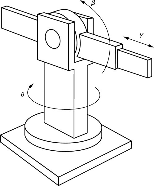
Spherical coordinate robots
The kinematic configuration of spherical coordinate robot arms is similar to the turret of a tank. These arms consist of a rotary base, an elevated pivot and a telescopic arm which moves in and out. The magnitude of rotation is usually measured by incremental encoders mounted on the rotary axes. The working envelope is a thick spherical shell.
The disadvantage of spherical robots compared with their cartesian counterparts is that there are two axes having a low resolution, which varies with the arm length.
The main advantage of spherical robots over the cartesian and cylindrical ones is a better mechanical flexibility. The pivot axis in the vertical plane permits convenient access to the base or under-the-base level. In addition, motions with rotary axes are much faster than those along linear axes.
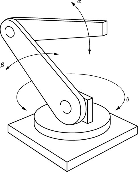
Revolute coordinate robots
The revolute, or articulated, robot consists of three rigid members connected by two rotary joints and mounted on a rotary base. It closely resembles the human arm. The end effector is analogous to the hand, which attaches to the forearm via the wrist. The elbow joint connects the forearm and the upper arm, and the shoulder joint connects the upper arm to the base. Sometimes a rotary motion in the horizontal plane is also provided at the shoulder joint.
Since the revolute robot has three rotary axes it has a relatively low resolution, which depends entirely on the arm length. Its accuracy is also the poorest since the articulated structure accumulates the joint errors at the end of the arm. The advantage of such a structure and configuration is that it can move at high speeds and has excellent mechanical flexibility, which has made it the most popular medium-sized robot.
The wrist
The end effector is connected to the mainframe of the robot through the wrist. The wrist includes three rotary axes, denoted by roll, pitch and yaw. The roll (or twist) is a rotation in a plane perpendicular to the end of the arm; pitch (or bend) is a rotation in a vertical plane and yaw is a rotation in the horizontal plane through the arm. However, there are applications which require only two axes of motion in the wrist.
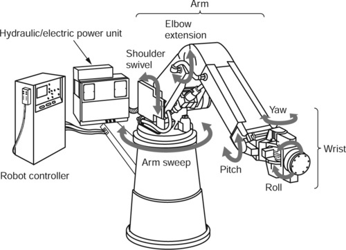
In order to reduce weight at the wrist, the wrist drives are sometimes located at the base of the robot, and the motion is transferred with rigid links or chains. Reduction of weight at the wrist increases the maximum allowable load and reduces the moment of inertia, which in turn improves the dynamic performance of the robot arm. The pitch, roll and yaw movements of the wrist can be seen on the robot shown.