
5.3 Power transmission: chain drives
The following information is taken from the Renold Chain Designer Guide with the permission of that company.
5.3.1 Chain performance
Renold chain products that are dimensionally in line with the ISO standard far exceed the stated ISO minimum tensile strength requirements. However Renold dues not consider breaking load to be a key indicator of performance because it ignores the principal factors of wear and fatigue. In these areas, Renold products are designed to produce the best possible results and independent testing proves this.
In this text, where the ISO breaking load is quoted, it should be noted that we are stating that the Renold product conforms to the ISO minimum standard. Independent test results show that the minimum (many companies quote averages) breaking loads were far in excess of the ISO minimum.
Where the quoted breaking load is nut described as being the ISO minimum, the product has nu relevant ISO standard. In this case, the breaking loads quoted are the minimum guaranteed.
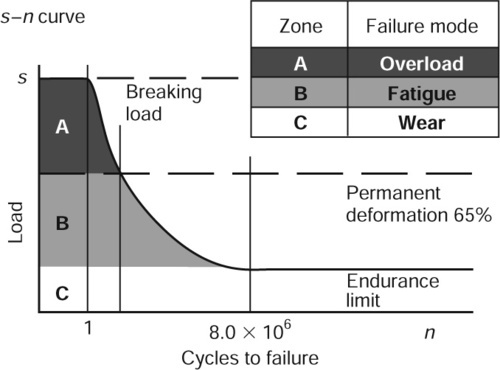
The performance of a chain is governed by a number of key factors. The tensile strength is the must obvious since this is the means by which a chain installation is roughly sized. However, since a chain is constructed from steel, the yield strength of which is around 65% of the ultimate tensile strength, any load above this limit will cause some permanent deformation to take place with consequent rapid failure.
Reference to the s-n curve below shows that at loads below this 65% line, finite life may be expected and at subsequent reductions in load the expected life increases until the fatigue endurance limit is reached at around 8000000 operations.
Loads below the endurance limit will result in infinite fatigue life. The failure mode will then become wear related which is far safer, since a controlled monitor of chain extension can take place at suitable planned intervals. In practice, if a load ratio of tensile strength to maximum working load of 8:1 is chosen, then the endurance limit will nut normally be exceeded. Careful consideration of the expected maximum working loads should be given since these are often much higher than the designer may think! It is also a requirement that any passenger lift applications are designed with a safety factor of nut less than 10:1.
In must applications the failure mode is designed to be wear and therefore some consideration of how a chain behaves in this mode are shown below.
Examination of the wear characteristics graph below shows that chain tends to wear in three distinct phases. The first phase, shown as ‘bedding in’, is a very rapid change in chain length associated with components adjusting to the loads imposed un them. The degree of this initial movement will depend to a large extent un the quality of chain used. Fur example, good component fits, chain preloaded at manufacture, plates assembled squarely, etc. Renold chain has many features that minimise the degree of bedding in.
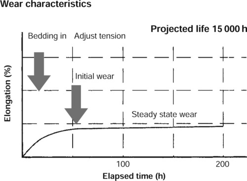
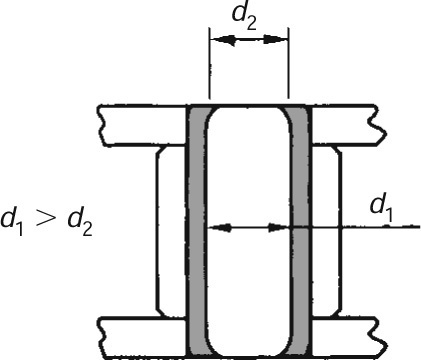
The second phase, shown as ‘initial wear’, might also be described as secondary ‘bedding in’. This is caused firstly by the rapid abrasion of local high spots between the mating surfaces of the pin and bush, and secondly by displacement of material at the bush ends. This is explained more clearly by the inner link assembly diagram shown, where it may be seen that in order to ensure good fatigue life, the bush and plate have a high degree of interference fit resulting in a tendency of the bush ends to collapse inwards slightly. This localised bulge will wear rapidly until the pin bears equally along the length of the bush. Renold limits this effect by introducing special manufacturing techniques. Some manufacturers maintain cylindricity by reducing the interference fit to a very low level. This reduces fatigue performance.
The final steady state of wear will continue at a very low rate until the chain needs renewal. In a correctly designed and lubricated system, 15000h continuous running should be normal.
The reason that wear takes place at all is demonstrated with reference to the Stribeck diagram below. It may be seen from this that where two mating surfaces are in contact, the coefficient of friction is very high at the point of initial movement, known as static friction. The reason for this is that the surface irregularities of the two bodies are interlocked with little or no separating lubrication layer. As the surface speeds increase, lubricant is drawn between the two surfaces and friction takes place with some surface contact. This condition is known as ‘mixed friction’. These two conditions result in material loss over time. With a continuing increase in surface speed, hydrodynamic friction takes place, a condition where there is no metal to metal contact.
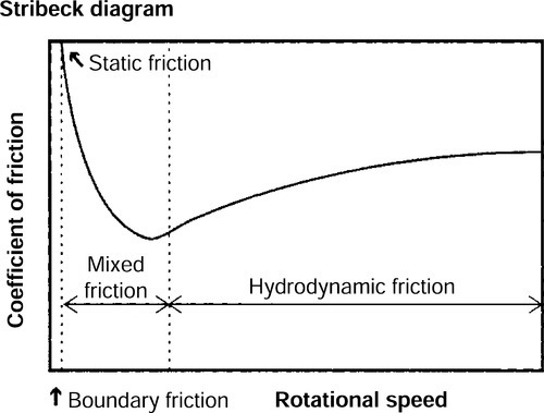
If we consider the action of the mating surfaces of the bush and pin during one cycle of a two sprocket system, it will quickly be realised that these components are stationary with respect to each other during travel from one sprocket to the other, and accelerate rapidly through a very small angle when engaging with the sprocket before coming to rest once more. This means that the pin/bush combination is operating between the static and mixed friction states and that lubrication will therefore be an important aspect of system design.
5.3.2 Wear factors
As already shown, wear takes place from the friction between the mating of the pin and bush. The rate of wear is primarily determined by the bearing area and the specific pressure on these surfaces. The hardened layers of the pin and bush are eroded in such a way that the chain will become elongated.
Elongation may amount to a Maximum of 2% of the nominal length of the chain. Above 2% elongation, there can be problems with the chain riding up and jumping the sprocket teeth.
Elongation should be limited to 1% when:
• A sprocket in the system has 90 teeth or more.
• Perfect synchronization is required.
• Centre distances are greater than recommended and not adjustable.
When the demands of the system become even higher, it is necessary to reduce the allowable percentage elongation further.
Wear depends on the following variables in a drive systemml:
• Speed The higher the speed of a system, the higher the frequency of bearing articulations, so accelerating wear.
• Number of sprockets The more sprockets used in a drive system, the more frequently the bearings articulate.
• Number of teeth The fewer the number of teeth in a sprocket, the greater the degree of articulation, the higher the wear.
• Chain length The shorter the length of chain, the more frequently the bearings in the chain will have to operate, the faster wear takes place.
• Lubrication As already shown, using the correct lubrication is critical to giving good wear life.
5.3.3 Chain types
Simplex chain

Duplex chain
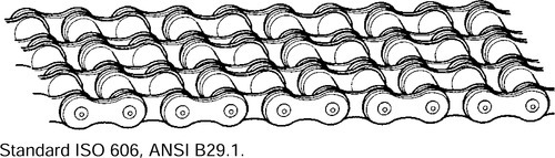
Triplex chain

As with all engineered products, industry demands that chain be produced to a formal standard. The key transmission chain standards are summarised in Sections 5.3.4 and 5.3.5 on pages 423 and 424.
5.3.4 International Standards
European Standard
Chains manufactured to the above standards are covered by ISO 606 and DIN 8187. These standards cover three versions:
• Duplex
• Triplex
The range of pitch sizes can vary between 4 mm, (0.158 in.) to 114.3 mm, (4.500 in.).
They are characterised by a large pin diameter, especially for the larger pitch sizes. This results in better wear resistance due to the greater bearing area.
The ISO Standard has a simple form of part numbering, for example 1/2 in. pitch duplex chain would be 08B-2.
• The first two digits are the pitch size in 1/16’s of an inch, therefore 08 = 8/16 or 1/2 in.
• The letter ‘B’ indicates European Standard.
• The suffix two indicates the number of strands in the chain, in this case a duplex chain.
American Standard
American Standard chains are covered by ISO 606, ANSI B29.1 and DIN 8188 and eight versions are covered.
• Simplex, duplex and triplex as for the European Standard chains
• Quadruplex, 4 strands
• Quintuplex, 5 strands
• Sextuplex, 6 strands
• Octuplex, 8 strands
• Decuplex, 10 strands.
The pitch sizes covered by this standard are 1/4 to 3 in. pitch.
American Standard chains have a smaller pin diameter than their European Standard equivalent. Wear resistance is therefore reduced when compared with European Standard chains with the one exception, 5/8in. pitch. In this case the pin and bush diameter is larger in an American Standard chain.
American Standard chains are normally referred to under the ANSI Standard numbering system, for example a 1/2 in. pitch duplex chain would be, ANSI 40-2.
The ANSI numbering system works as follows:
• The first number is the pitch size in 1/8 in.; that is, 4/8 = 1/2 in. pitch.
• The second number refers to the chain being a roller chain, 0 = roller chain. A 5 replacing the 0 would indicate a bush chain.
• The suffix, as with European Standard chain, refers to the number of strands in the chain, that is 2 = duplex chain.
ANSI chain is also available in heavy duty options with thicker plates (H) and through hardened pins (V). An ANSI heavy chain would be specified using these suffixes. That is,
ANSI 140-2HV Duplex, thick plates, through hardened pin
ANSI 80H Simplex, thick plates
Range of application
The transmission chain market worldwide is divided between these two chain standards, based on the economic and historical influences within their regions.
• American Standard chain is used primarily in the USA, Canada, Australia, Japan and some Asiatic countries.
• European Standard chains dominate in Europe, the British Commonwealth, Africa and Asian countries with a strong British historical involvement.
In Europe around 85% of the total market uses European Standard chain. The remaining 15% is American Standard chains found on:
• Machinery imported from countries where American Standard chain dominates.
• Machinery manufactured in Europe under licence from American dominated markets.
Chain not conforming to ISO Standards
There are also Renold manufacturing standards for special or engineered chain which can be split as follows:
1. Higher breaking load chain This chain usually has plates that undergo a special treatment, has thicker side plate material and/or pin diameters that slightly deviate from the standards.
2. Special dimensions Some chains can be a mixture of American and European Standard dimensions or the inner width and roller diameters vary, such as in motorcycle chains.
3. Applicational needs Special or engineered chain is manufactured for specific applicational use, examples being:
• Zinc or nickel plated chain
• Chain with plastic lubricating bushes
• Chains with hollow bearing pins
• Chain that can bend sideways (SIDEBOW).
5.3.5 Standards reference guide
Transmission chain type
| ISO | ANSI | Other | |
| Short pitch transmission chain and sprockets | 606 | B29.1M | DIN 8187 |
| DIN 8188 | |||
| Short pitch bush chains and sprockets | 1395 | DIN 8154 | |
| Double pitch roller chain and sprockets | 1275 | B29.3M | DIN 8181 |
| Oilfield chain and sprockets | 606 | B29.1M | API Spec 7F |
| Cycle chains | 9633 | ||
| Motorcycle chains | 10190 | ||
| Cranked link chain and sprockets | 3512 | B29.1M | DIN 8182 |

Lifting chain types

5.3.6 Advantages of chain drives
Steel transmission roller chain is made to close tolerances with excellent joint articulation, permitting a smooth efficient flow of power. Any friction between the chain rollers and sprocket teeth is virtually eliminated because the rollers rotate on the outside of the bushes, independent of bearing pin articulation inside the bush. As a result, very little energy is wasted and tests have shown chain to have an efficiency of between 98.4% and 98.9%.
This high level of efficiency, achieved by a standard stock chain drive under the correct conditions of lubrication and installation, is equalled only by gears of the highest standard with teeth ground to very close tolerances.
Roller chain offers a positive, non-slip driving medium. It provides an accurate pitch by pitch positive drive which is essential on synchronised drives such as those to automobile and marine camshafts, packaging and printing machinery. Under conditions of high speed and peak load when efficiency is also required, the roller chain has proved consistently quiet and reliable.
Centre distances between shafts can range from 50 mm up to more than 9 m in a very compact installation envelope. Drives can be engineered so that the sprocket teeth just clear each other or so that a considerable span is traversed by the chain. In this later category, double pitch chain comes into its own.
Roller chain has a certain degree of inherent elasticity and this, plus the cushioning effect of an oil film in the chain joints, provides good shock absorbing properties. In addition, the load distribution between a chain and sprocket takes place over a number of teeth, which assists in reducing wear. When, after lengthy service, it becomes necessary to replace a chain, this is simple and does not normally entail sprocket or bearing removal.
Roller chain minimises loads on the drive motor and driven shaft bearings since no preload is required to tension the chain in the static condition.
One chain can drive several shafts simultaneously and in almost any configuration of centre distance or layout. Its adaptability is not limited to driving one or more shafts from a common drive point. It can be used for an infinite variety of devices including reciprocation, racks, cam motions, internal or external gearing, counterbalancing, hoisting or weight suspension. Segmental tooth or ‘necklace’ chain sprocket rims can be fitted to large diameter drums.
Since there are no elastomeric components involved, chain is tolerant of a wide variety of environmental conditions, including extremes of temperature. Chain is used successfully in such harsh environments as chemical processing, mining, baking, rock drilling and wood processing. Special coatings can easily be applied for further enhancement.
Roller chain can also be fitted with link plate attachments and extended bearing pins, etc., which allow them to be used for mechanical handling equipment and the operation of mechanisms.
Roller chain drives are available for ratios up to 9:1 and to transmit up to 520 kW at 550 rev/min. Beyond this, four matched strands of triplex chain can achieve 3200 kW at 300 rev/min.
Roller chain does not deteriorate with the passage of time, the only evidence of age being elongation due to wear which normally is gradual and can be accommodated by centre distance adjustment or by an adjustable jockey sprocket. Provided a chain drive is selected correctly, properly installed and maintained, a life of 15 000 h can be expected without chain failure either from fatigue or wear.
Where complete reliability and long life are essential, chains can be selected on their assured performance for applications such as hoists for control rods in nuclear reactors and control systems for aircraft.
Chain is a highly standardised product available in accordance with ISO Standards all over the world. It is also totally recyclable and causes no harmful effects to the environment.
Shown below is a simple table comparing the merits of different transmission/lifting media.
Summary of advantages
| Feature | Gears | Rope | Belt | Chain |
| Efficiency | A | X | B | A |
| Positive drive | A | X | B | A |
| Centre distance | C | A | B | A |
| Elasticity | C | A | A | B |
| Wear resistance | A | C | B | A |
| No pre-load | A | C | C | A |
| Multiple drives | C | X | C | A |
| Heat resistant | B | B | C | A |
| Chemical resistant | B | A | C | A |
| Oil resistant | A | A | C | A |
| Adaptations | C | B | C | A |
| Power range | A | X | B | A |
| Ease of maintenance | C | B | B | A |
| Standardized | C | B | B | A |
| Environment | A | A | C | A |
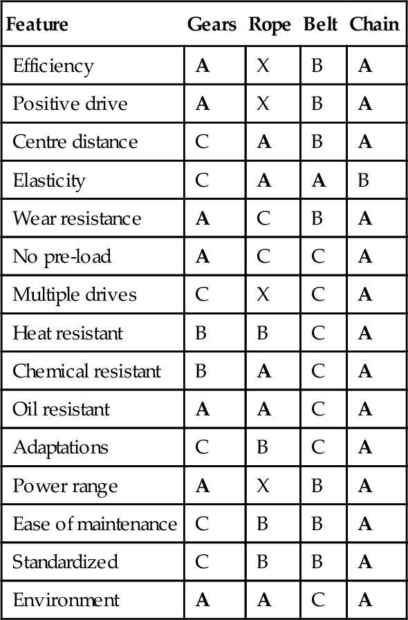
A = excellent B = good
C = poor X = not appropriate
Note: To achieve the above ratings, different types of belt would be required.
5.3.7 Chain selection
The notes given below are general recommendations and should be followed in the selection and installation of a chain drive, in order that satisfactory performance and drive life may be ensured.
Chain pitch
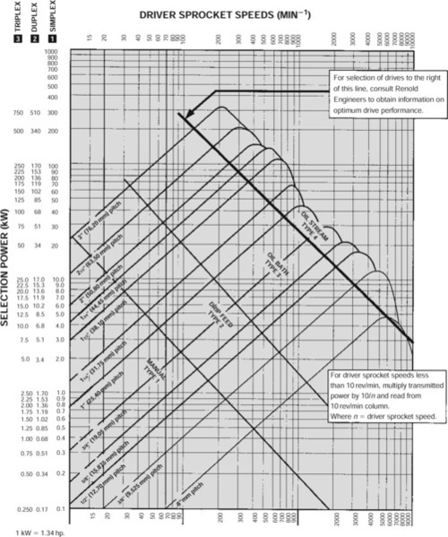
The Rating Charts (pages 441 and 442) give the alternative sizes of chains that may be used to transmit the load at a given speed. The smallest pitch of a simplex chain should be used, as this normally results in the most economical drive. If the simplex chain does not satisfy the requirements dictated by space limitations, high speed, quietness or smoothness of running, then consider a smaller pitch of duplex or triplex chain.
When the power requirement at a given speed is beyond the capacity of a single strand of chain, then the use of multistrand drives permits higher powers to be transmitted.
These drives can also be made up from multiples of matched simplex, duplex or triplex ISO chains or in the case of ANSI chain, multiplex chain up to decuplex (10 strands) are available.
Please consult Renold’s technical staff for further information (see Appendix 3).
Maximum operating speeds
For normal industrial drives, experience has established a maximum sprocket speed for each pitch of chain. These speeds, which relate to driver sprockets having 17-25 teeth inclusive, are given in the graph below; they are applicable only if the method of lubrication provided is in line with recommendations.

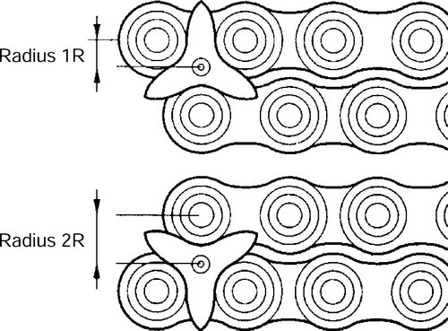
Polygonal effect
Four important advantages of a chain drive are dependent directly upon the number of teeth in the driver sprocket (Z1).
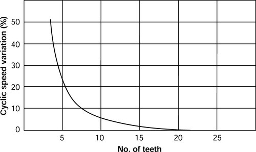
The advantages are smooth uniform flow of power, quietness of operation, high efficiency and long life, the reason for their dependence being that chain forms a polygon on the sprocket. Thus, when the sprocket speed is constant, the chain speed (due to the many sided shape of its path around the teeth) is subject to a regular cyclic variation. This cyclic variation becomes less marked as the path of the chain tends towards a true circle and in fact, becomes insignificant for most applications as the number of teeth in the driver sprocket exceeds 19.
The effect of this cyclic variation can be shown in the extreme case of a driver sprocket with the absolute minimum number of teeth; that is, three. In this instance, for each revolution of the sprocket the chain is subjected to a three-phase cycle; each phase being associated with the engagement of a single tooth. As the tooth comes into engagement, for a sixth of a revolution the effective distance, or driving radius from the sprocket centre to the chain is gradually doubled; for the remaining sixth of a revolution, it falls back to its original position. Thus, as the linear speed of the chain is directly related to the effective driving radius of the driver sprocket, the chain speed fluctuates by 50% six times during each revolution of the driver sprocket.
As the graph below shows, the percentage of cyclic speed variation decreases rapidly as more teeth are added. With the driver sprocket of 19 teeth, therefore, this cyclic speed variation is negligible; hence we recommend that driver sprockets used in normal application drives running at medium to maximum speeds, should have not less than 19 teeth.
There are, however, applications where space saving is a vital design requirement and the speed/power conditions are such that the smaller numbers of teeth (i.e. below 17) give acceptable performance so that a compact, satisfactory drive is achieved; for example, office machinery, hand operated drives, mechanisms, etc.
The limiting conditions with steady loading for using small numbers of teeth are:
5.3.8 Sprocket and chain compatibility
Most drives have an even number of pitches in the chain and by using a driver sprocket with an odd number of teeth, uniform wear distribution over both chain and sprocket teeth is ensured. Even numbers of teeth for both the driver and driven sprockets can be used, but wear distribution on both the sprocket teeth and chain is poor.
Number of teeth
The maximum number of teeth in any driven sprocket (Z2) should not exceed 114. This limitation is due to the fact that for a given elongation of chain due to wear, the working pitch diameter of the chain on the sprocket increases in relation to the nominal pitch diameter; that is, chain assumes a high position on the sprocket tooth. The allowable safe chain wear is considered to be in the order of 2% elongation over nominal length.
A simple formula for determining how much chain elongation a sprocket can accommodate is 200/N expressed as percentage where N is the number of teeth on the largest sprocket in the drive system.
It is good practice to have the sum of teeth not less than 50 where both the driver and driven sprockets are operated by the same chain, for example, on a 1:1 ratio drive, both sprockets should have 25 teeth each.
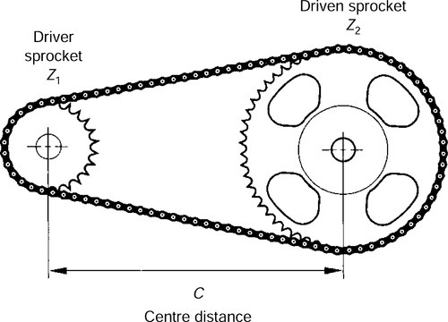
Centre distance
For optimum wear life, centre distance between two sprockets should normally be within the range 30-50 times the chain pitch. On drive proposals with centre distances below 30 pitches or greater than 2 m, we would recommend that the drive details are discussed with Renold’s technical staff.
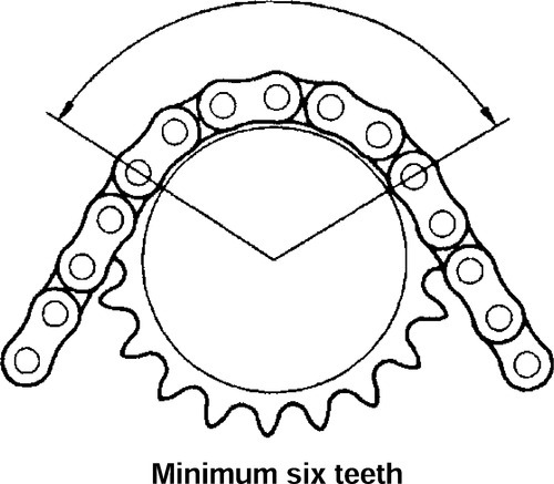
The minimum centre distance is sometimes governed by the amount of chain lap on the driver sprocket, our normal recommendation in this circumstance being not less than 6 teeth in engagement with the chain.
The centre distance is also governed by the desirability of using a chain with an even number of pitches to avoid the use of a cranked link, a practice that is not recommended except in special circumstances.
For a drive in the horizontal plane the shortest centre distance possible should be used consonant with recommended chain lap on the driver sprocket.
Formulae for the calculation of chain length and centre distance for two-point drives are given on page 437.


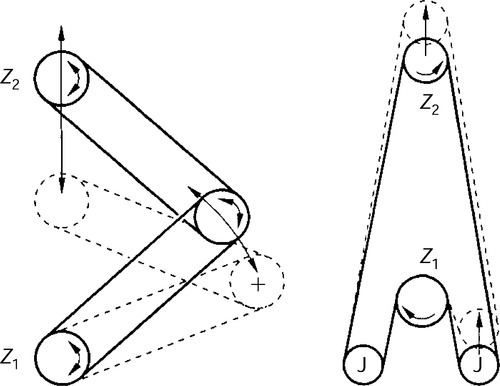
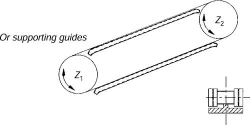
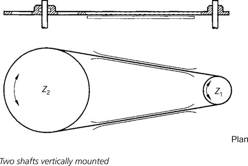
Lie of drive
Drives may be arranged to run horizontally, inclined or vertically. In general, the loaded strand of the chain may be uppermost or lowermost as desired. Where the lie of the drive is vertical, or nearly so, it is preferable for the driver sprocket (Z1) to be above the driven sprocket (Z2); however, even with a drive of vertical lie it is quite feasible for the driver sprocket to be lowermost, provided care is taken that correct chain adjustment is maintained at all times.
Centres
The centre distance between the axis of two shafts or sprockets.

Angle
The lie of the drive is given by the angle formed by the line through the shaft centres and a horizontal line.

Rotation
Viewed along the axis of the driven shaft the rotation can be clockwise or anti-clockwise.
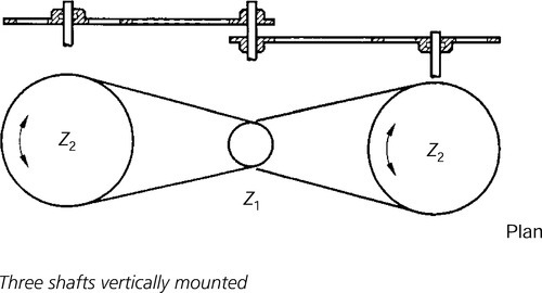
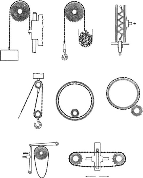
5.3.9 Drive layout
One chain can be used for driving a number of shafts and due to the ability of roller chains to gear on either face, individual shafts in the same drive can be made to rotate in the same or opposite directions by arranging the driven sprockets to gear in different faces of the chain. The number of driven sprockets permissible in any one drive depends on the layout.
A selection of possible drive layouts is shown below.
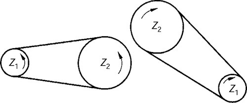
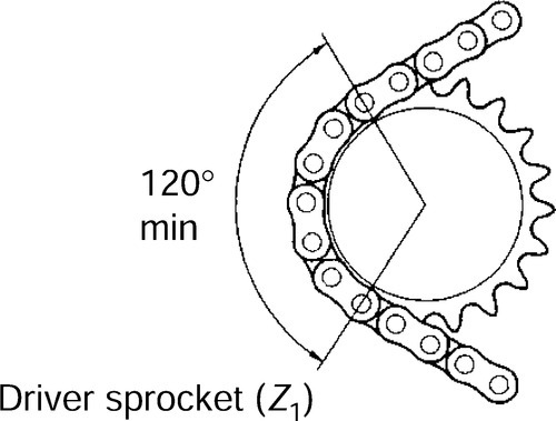
Drives with variable shaft positions
Chain lap: Recommended 120°. Minimum of 90° permissible for sprockets of 27 teeth or over.
Centres: Pitch of chain multiplied by 30-50.
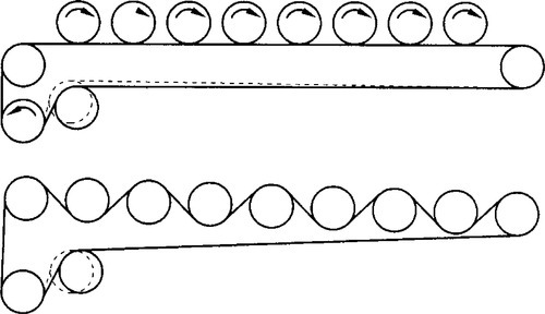
Drives with abnormally long centres
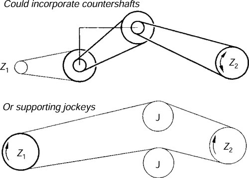
For slow and medium chain speed applications up to 150 m/min.
For applications where countershafts or supporting jockeys cannot be employed and where the chain speed does not exceed 60 m/min.
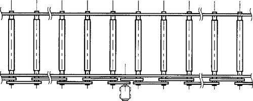
Multi-shaft drives
The permissible number of driven shafts will vary according to drive characteristics.

Whilst the efficiency of a single stage drive is approximately 98%, where a series of drives are interconnected as in live roller conveyors, the overall efficiency will vary with the number of drives involved. It is necessary in applications of this nature to increase the calculated motor power to allow for this reduced efficiency.
4 drives overall efficiency = 94%
8 drives overall efficiency = 87%
12 drives overall efficiency = 80%

The jockey is used to ensure adequate chain lap on the driven sprockets.
Horizontal drives
When centres are long, use guide strips to support chain strands with generous ‘lead-in’ to ensure smooth entry and exit of chain.
Chain lap: Recommended 120°. Minimum of 90° permissable for sprockets of 27 teeth or over.
Centres: Shortest possible.
5.3.10 Selection method
Introduction
Chain selected using this method will have a minimum life expectancy with proper installation and lubrication of 15 000 h.
Warning
The rating charts pages 441 and 442 exceed the minimum standards and selection of chain using the figures quoted in this section is only valid for Renold chain.
Use Renold’s interactive Chain Selector on www.renold.com.
Symbols, terms and units
Z1 = number of teeth on drive sprocket.
Z2 = number of teeth on driven sprocket.
C = centre distance (mm).
P = chain pitch (mm).
i = drive ratio.
L = chain length (pitches).
In order to select a chain drive the following essential information must be known:
• The power in kilowatts to be transmitted.
• The speed of the driving and driven shafts.
• The characteristics of the drive.
• Centre distance.
From this base information, the selection power to be applied to the ratings chart is derived.
Selection summary
| 1 | Select drive ratio and sprockets Z1 = 19 teeth minimum | 434 |
| 2 | Establish selection application factors F1 takes account of dynamic loads Tooth factor f2(19/Z1) | 435 |
| 3 | Calculate selection power = power × f1 × f2(kW) | 436 |
| 4 | Select chain drive. Use rating charts | 437/441/442 |
| 5 | Calculate chain length using formulae | 437 |
| 6 | Calculate exact centre distance | 437 |
Finally, choose lubrication method.
Select drive and ratio
Chart 1 may be used to choose a ratio based on the standard sprocket sizes available. it is best to use an odd number of teeth combined with an even number of chain pitches.
Ideally, chain sprockets with a minimum of 19 teeth should be chosen. If the chain drive operates at high speed or is subjected to impulsive loads, the smaller sprockets should have at least 25 teeth and should be hardened.
It is recommended that chain sprockets should have a maximum of 114 teeth.
Drive ratio can otherwise be calculated using the formula:
![]()
For large ratio drives, check that the angle of lap of Z1 is not less than 120°.
![]()
Chain reduction ratios to one using preferred sprockets
| No. of teeth driven sprocket Z2 | No. of teeth drive sprocket Z1 | |||||
| 15 | 17 | 19 | 21 | 23 | 25 | |
| 25 | – | – | – | – | – | 1.00 |
| 38 | 2.53 | 2.23 | 2.00 | 1.80 | 1.65 | 1.52 |
| 57 | 3.80 | 3.35 | 3.00 | 2.71 | 2.48 | 2.28 |
| 76 | 5.07 | 4.47 | 4.00 | 3.62 | 3.30 | 3.04 |
| 95 | 6.33 | 5.59 | 5.00 | 4.52 | 4.13 | 3.80 |
| 114 | 7.60 | 6.70 | 6.00 | 5.43 | 4.96 | 4.56 |
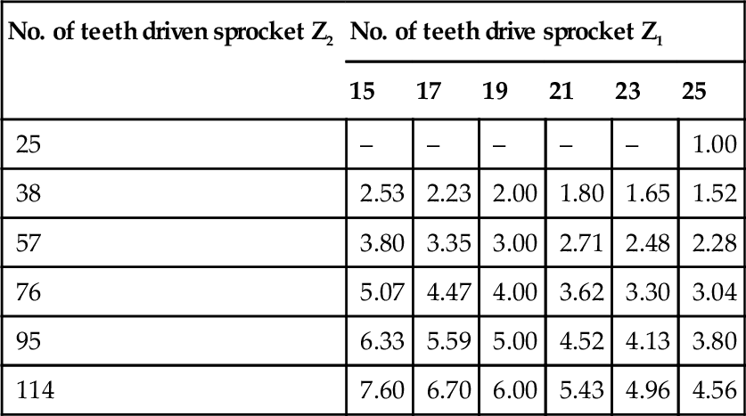
For recommended centre distances see page 437
Establish selection factors
The following factors will be used later on to determine the selection power.
Application factor f1
Factor f1 takes account of any dynamic overloads depending on the chain operating conditions. The value of factor f1 can be chosen directly or by analogy using chart 2.
| Driven machine characteristics | Characteristics of driver | |||
| Smooth running Electric motors, steam and gas turbines, internal combustion engines with hydraulic coupling | Slight shocks Internal combustion engines with six cycles or more with mechanical coupling, electric motors with frequent starts | Moderate shocks Internal combustion engines with less than six cycles with mechanical coupling | ||
| Smooth running | Centrifugal pumps and compressors, printing machines, paper calanders, uniformly loaded conveyors, escalators, liquid agitators and mixers, rotary driers, fans | 1 | 1.1 | 1.3 |
| Moderate shocks | Pumps and compressors (3+ cycles), concrete mixing machines, non uniformly loaded conveyors, solid agitators and mixers | 1.4 | 1.5 | 1.7 |
| Heavy shocks | Planers, excavators, roll and ball mills, rubber processing machines, presses and shears one and two cycle pumps and compressors, oil drilling rigs | 1.8 | 1.9 | 2.1 |

Tooth factor f2
The use of a tooth factor further modifies the final power selection. The choice of a smaller diameter sprocket will reduced the maximum power capable of being transmitted since the load in the chain will be higher.
Tooth factor f2 is calculated using the formula
![]()
Note that this formula arises due to the fact that selection rating curves shown in the rating charts (see pages 441 and 442) are those for a 19 tooth sprocket.

Calculate the selection power
Multiply the power to be transmitted by the factors obtained from step two.
Selection power = Power to be transmitted × f1 × f2(kW).
This selection power can now be used with the appropriate rating chart, see pages 441 and 442.
Select chain drive
From the rating chart, select the smallest pitch of simplex chain to transmit the selection power at the speed of the driving sprocket Z1.
This normally results in the most economical drive selection. If the selection power is now greater than that shown for the simplex chain, then consider a multiplex chain of the same pitch size as detailed in the ratings chart.
Calculate chain length
To find the chain length in pitches (L) for any contemplated centre distance of a two point drive, use the formula below:
The calculated number of pitches should be rounded up to a whole number of even pitches. Odd numbers of pitches should be avoided because this would involve the use of a cranked link which is not recommended. If a jockey sprocket is used for adjustment purposes, two pitches should be added to the chain length (L).
C is the contemplated centre distance in mm and should generally be between 30 and 50 pitches.
For example, for 1![]() in. pitch chain C = 1.5 × 25.4 × 40 = 1524 mm.
in. pitch chain C = 1.5 × 25.4 × 40 = 1524 mm.
Calculate exact centre distance
The actual centre distance for the chain length (L) calculated by the method above, will in general be greater than that originally contemplated. The revised centre distance can be calculated from the formula below.
![]()
where:
P = chain pitch (mm)
L = chain length (pitches)
Z1 = number of teeth in driver sprocket
Z2 = number of teeth in driver sprocket
Drive with multiple sprockets
When designing a drive with multiple sprockets, the chain length calculation becomes more complicated. Most CAD systems, however, can be used to calculate chain length by wrapping a polyline around the pitch circle diameter (PCD’s) of each sprocket. A scale manual drawing could also give a fairly accurate result as follows:

Measure lengths LTi
Measure angles βi
The theoretical length in pitches can now be calculated by the addition of all LT and β values using the following formula.
where:
P = the chain pitch
![]()
This calculation method can also be applied on drives where the chain is driven on guide rails or around jockey sprockets. These should be considered as ordinary sprockets.
Sprockets for transmission chain
Renold manufacture a comprehensive range of stock sprockets for European standard chains up to 2 in. pitch.
Other sizes of sprocket, including those to American standard dimensions, are available on request.
Special sprockets are also manufactured on request, in special materials or formats, normally to suit a specific application in harsh or difficult drive situations, examples being:
• Sprockets incorporating shafts.
• Welded or detachable hubs.
• Shear pin devices fitted.
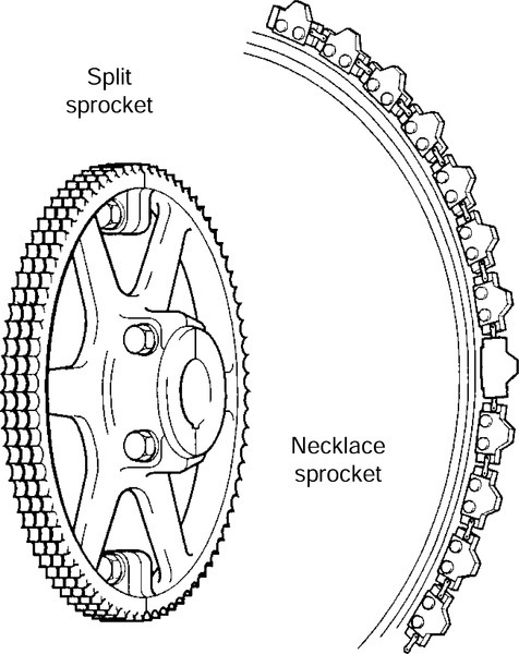
• Necklace sprockets made up of chain plates and individual tooth sections for turning large drums or tables.
• Combination sprockets (two or more sprockets combined having different pitch sizes and numbers of teeth).
• Sprockets in two or more sections, that is, split sprockets or segmental sprockets.
Examples of two typical special sprockets.
Selection of sprocket materials
Choice of material and heat treatment will depend upon shape, diameter and mass of the sprocket. The table below can be used as a simple guide on the correct selection of sprocket material.
| Sprocket | Smooth running | Moderate shocks | Heavy shocks |
| Up to 29T | EN8 or EN9 | EN8 or EN9 hardened and tempered or case hardened mild steel | EN8 or EN9 hardened and tempered or case hardened mild steel |
| 30T and over | Cast iron | Mild steel or meehanite | EN8 or EN9 hardened and tempered or case hardened mild steel |

Kilowatt ratings, for European and ANSI chains, shown in the ratings charts on pages 441 and 442 are based on the following conditions:
(b) Wheel centre distance of 30-50 times the chain pitch.
(c) Speed of driver sprocket (Z1)whether on the driving or driven shaft.
(d) Two sprocket drive arrangement.
(e) Adjustment by centre distance or jockey on unloaded strand.
(f) Riveted endless chain (press fit connector).
(g) Correct lubrication.
(h) Accurate shaft/sprocket alignment.
Under these conditions a service life of approximately 15 000 h can ordinarily be expected when the chain operates under full rating. The kilowatt ratings for multiple strand European chains up to triplex are given respectively in columns 2 and 3, for ANSI chains up to quadruplex in columns 2, 3 and 4.
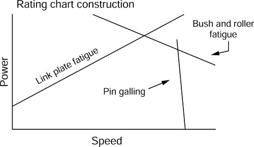
5.3.11 Rating chart construction
The rating charts at first sight look complicated, however, they are constructed from three simple lines. From this it may be seen that at lower speeds the failure mode is likely to be plate fatigue if the maximum power recommendation is exceeded. However, pin galling will occur due to boundary lubrication break down at very high speeds. At the intersection of these lines the bush and roller fatigue curve comes into a play and accounts for the rounded tops to each of the selection curves.
Bearing pressures
When a chain has been correctly selected, the mode of failure over a very long period of time is most likely to be wear.
The subject of wear, which depends on many factors, has been addressed earlier in this guide, however, a very useful indicator of the likely wear performance is the magnitude of pressure between the key mating surfaces, that is, pin and bush.
This pressure is known as the bearing pressure, and is obtained by dividing the working load by the bearing area. Bearing areas for standard chains are quoted in the designer data at the end of this guide.
The following table gives an indication of the implications of various bearing pressures but should not be used without reference to the other chain selection methods given in this guide.
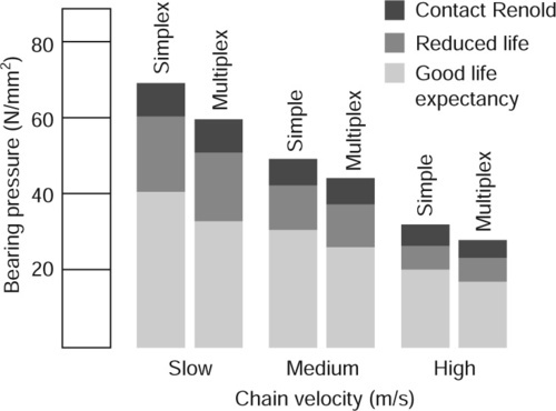
Slow velocity up to 60% of maximum allowable speed.
Medium velocity 60-80% of maximum allowable speed.
High velocity over 80% of maximum allowable speed.
Note: There is some variation between chains, and the above figures should be used as a guide only.
5.3.12 European chain rating chart
European Standard chain drives
Rating chart using 19T driver sprocket
5.3.13 ANSI rating chart
American Standard chain drives
Rating chart using 19T driver sprocket

Transmission equations
The following equations give the relationships between power, torque and velocity for various drive arrangements.

where:
Md = torque of the driver sprocket (Nm)
Pr = power (kW)
d1 = pitch circle diameter of the driver sprocket (mm)
n1 = driver sprocket speed (rev/min)
Z1 = number of teeth in the driver sprocket
Z2 = number of teeth in the driven sprocket
v = linear speed of the chain (m/s)
F1 = chain pull (N)
P = pitch of the chain (mm)
Centripetal acceleration
Centripetal acceleration affecting parts of the chain engaged on the sprockets is determined by:
![]()
where:
F2 = force (N)
q = mass of the chain (kg/m)
From this formula we can see that at high speed, this force is not negligible and is the main reason for speed limitation.
5.3.14 Chain suspension force
The force acting between one link and the next due to the mass of the chain is small and is internally balanced within the chain. This will do no more than cause the chain to adopt a sagging catenery shape between the sprockets.
Allowance will need to be made in the installation for the slightly different postures adopted by the chain between zero and maximum load.
5.3.15 Lubrication
Chain drives should be protected against dirt and moisture and be lubricated with good quality non-detergent mineral based oil. A periodic change of oil is desirable. Heavy oils and greases are generally too stiff to enter the chain working surfaces and should not be used.
Care must be taken to ensure that the lubricant reaches the bearing areas of the chain. This can be done by directing the oil into the clearances between the inner and outer link plates, preferably at the point where the chain enters the sprocket on the bottom strand.
The table below indicates the correct lubricant viscosity for various ambient temperatures.
| Ambient temperature °C | Lubricant rating | |
| SAE | BS 4231 | |
| − 5 to +5 | 20 | 46 to 68 |
| 5 to 40 | 30 | 100 |
| 40 to 50 | 40 | 150 to 220 |
| 50 to 60 | 50 | 320 |
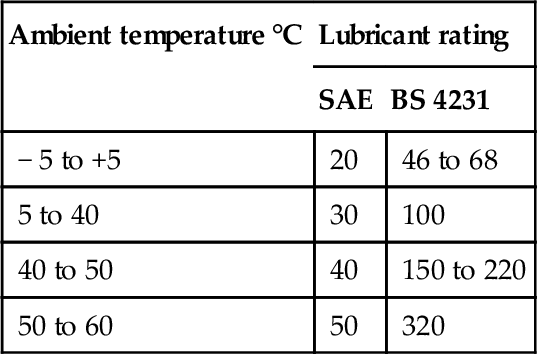
For the majority of applications in the above temperature range, a multigrade SAE 20/50 oil would be suitable.
Use of grease
As mentioned above, the use of grease is not recommended. However, if grease lubrication is essential, the following points should be noted:
• Applying normal greases to the outside surfaces of a chain only seals the bearing surfaces and will not work into them. This causes premature failure. Grease has to be heated until fluid and the chain is immersed and allowed to soak until all air bubbles cease to rise. If this system is used, the chains need regular cleaning and regreasing at intervals depending on the drives’ power and speed. It should also be noted that temperatures above 80°C will cause damage to many greases and reduce their effectiveness.
Abnormal ambient temperatures
For elevated temperatures up to 250°C, dry lubricants such as colloidal graphite or MoS2 in white spirit or poly-alkaline glycol carriers are most suitable.
Conversely, at low temperatures between −5°C and −40°C, special low temperature initial greases and subsequent oil lubricants are necessary. Lubricant suppliers will give recommendations.
5.3.16 Lubricating methods
There are four basic methods for lubricating chain drives. The recommended lubrication method is based on the chain speed and power transmitted, and can be found in the rating charts (see pages 441 and 442).
Type 1, Manual operation
Oil is applied periodically with a brush or oil can, preferably once every 8h of operation. Volume and frequency should be sufficient to just keep the chain wet with oil and allow penetration of clean lubricant into the chain joints.
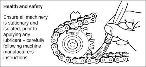
Applying lubricant by aerosol is also a satisfactory method, but it is important that the aerosol lubricant is of an approved type for the application, such as that supplied by Renold. This type of lubricant ‘winds’ in to the pin/bush/roller clearances, resisting both the tendency to drip or drain when the chain is stationary and centrifugal ‘flinging’ when the chain is moving.
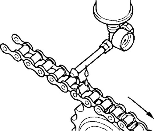
Type 2, Drip lubrication
Oil drips are directed between the link plate edges from a drip lubricator. Volume and frequency should be sufficient to allow penetration of lubricant into the chain joints.
Type 3, Bath or disc lubrication
With oil bath lubrication the lower strand of chain runs through a sump of oil in the drive housing. The oil level should cover the chain at its lowest point whilst operating.
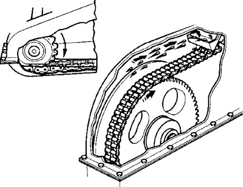
With slinger disc lubrication an oil bath is used, but the chain operates above the oil level. A disc picks up oil from the sump and deposits it on the chain by means of deflection plates. When such discs are employed they should be designed to have peripheral speeds between 180 and 2440 m/min.
Type 4, Stream lubrication
A continuous supply of oil from a circulating pump or central lubricating system is directed onto the chain. It is important to ensure that the spray holes from which the oil emerges are in line with the chain edges. The spray pipe should be positioned so that the oil is delivered onto the chain just before it engages with the driver sprocket.
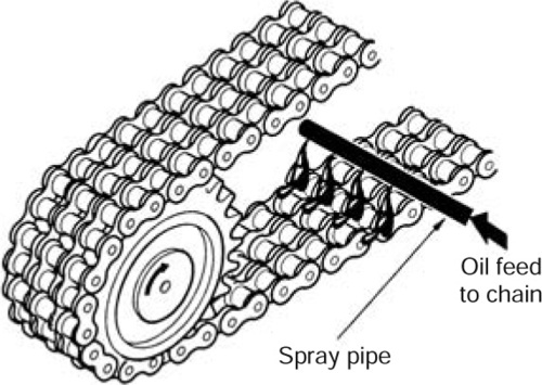
This ensures that the lubricant is centrifuged through the chain and assists in cushioning roller impact on the sprocket teeth. Stream lubrication also provides effective cooling and impact damping at high speeds.
Effect of temperature
An important factor to control in a drive system is the chain and chaincase temperatures during operation. Depending on the severity of the drive service, continuity of use, etc., special attention to the lubrication method may be required.
Chain temperatures above 100°C should be avoided if possible due to lubrication limitations, although chain can generally give acceptable performance up to around 250°C in some circumstances. A way of improving the effectiveness of the lubrication and its cooling effect is to increase the oil volume (up to 4.5l/min per chain strand) and incorporate a method of external cooling for the oil.
5.3.17 Lifting applications
This section covers applications, such as lifting and moving, where the loads involved are generally static. Obviously, dynamic loads are also involved in most applications and the designer needs to take due consideration of these. The machinery designer should also refer to DTI Publication INDY J1898 40M which summarises legislation in place from 1st January 1993 to 1st January 1995 regarding machinery product standards.
Chain for lifting applications falls into two main categories:
• Bush and roller chains.
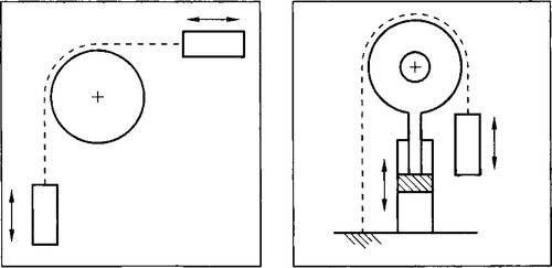
Leaf chain
Leaf chain is generally used for load balancing type lifting applications as illustrated below. They must be anchored at either end since there is no means of geared engagement in the chain itself.
Safety factors
A safety factor of 7:1 is normal for steady duty reciprocating motion, for example, fork lift trucks. For medium shock loads, 9:1 and for heavy shock loads, 11:1.
Operating speed
Applications should not exceed a maximum chain speed of 30 m/min.
Applications
1. Machine tools – planers, drills, milling heads, machine centres.
2. Fork lift trucks, lifts, hoists.
3. Counterweight balances – jacks, doors, gates, etc.
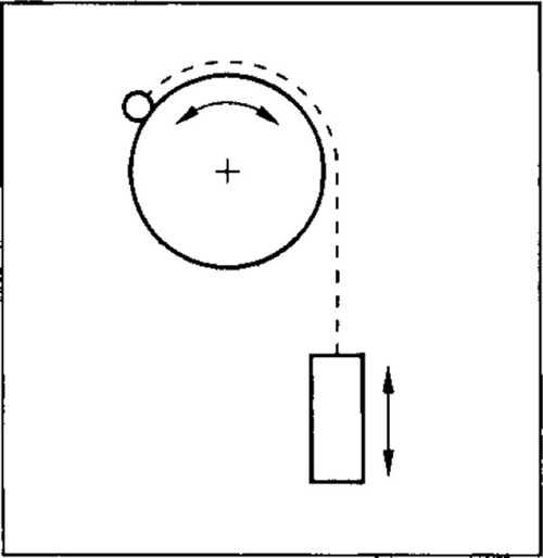
Bush and Roller chains
Bush and roller chains can be used for lifting and moving purposes, and have the advantage over leaf chain in that they may be geared into a suitable driving sprocket. Roller chain has a better wear resistance than leaf chain and may be used at higher speeds.
Safety factors
Applications vary widely in the nature of loads applied and it is therefore recommended that factors of safety are applied which allow for some degree of abuse:
• A factor of safety of 8:1 in non-passenger applications.
• factor of safety of 10:1 in passenger applications.
Lower factors of safety than these may be used (except for passenger applications), where careful consideration of the maximum loads and health and safety implications have been made. For comments on this see the section ‘Influences on chain life’.
Operating speeds
Applications should not normally exceed a maximum chain speed of 45m/min. For speeds higher than this, consider selection as if the chain were in a power transmission application converting the chain load to power using the following formula:
Power = FV (kW)
where:
F = Load (kN)
V = Velocity of chain (m/s)
Then apply selection power factors as shown in step two of ‘Drive Selection’.
Calculate equivalent rev/min by using the smallest sprocket in the system where
![]()
where:
P = Chain pitch (mm)
Z = No of teeth in sprocket
Select lubrication methods also from the selection chart.
5.3.18 ANSI Xtra range
Transmission chain is also available in heavy duty versions of the ANSI standard range of chain.
These chains are suitable where frequent or impulsive load reversals are involved. Typical applications are in primary industries, such as mining, quarrying, rock drilling, forestry and construction machinery.
In order to accommodate these higher fatigue inducing loads, material for inner and outer plates is increased in thickness by approximately 20%.
This modification does not improve the tensile strength since the pin then becomes the weakest component. However, heavy duty chains with higher tensile strength are available. This is achieved by through hardening instead of case hardening the pin, but unfortunately this action reduces wear performance due to the lower pin hardness.
Renold ANSI Xtra chains are available as follows:
• Xtra V range Through hardened pins
• Xtra HV range Thicker plates and through hardened pins.
The H and HV chains are not suitable or appropriate for high speed transmission applications.
The following points should also be noted:
• The V range of chains are totally interchangeable with standard ANSI chain.
• Simple chains of standard, H or HV designs all have identical gearing dimensions and therefore can operate on the same sprockets as for standard chains. The thicker plates will require a larger chain track and it may be desirable to use sprockets with heat treated teeth. Multiplex chain requires an increased transverse pitch of the teeth but other gearing dimensions are the same.
• The only reason to use H or HV chains is where fatigue life is a problem. We do not make any cranked (offset) links or slip-fit connecting links for this range, since these have a lower fatigue resistance.
• Detachable (cottered) versions can be produced if required as could triplex or wider chains.
5.3.19 Influences on chain life
Factors of safety
All Renold chain is specified by its minimum tensile strength. To obtain a design working load it is necessary to apply a ‘factor of safety’ to the breaking load. However, before considering this, the following points should be noted:
• Most chain side plates are manufactured from low to medium carbon steel and are sized to ensure they have adequate strength and also ductility to resist shock loading.
• These steels have yield strengths around 65% of their ultimate tensile strength. What this means is that if chains are subjected to loads of greater than this, depending on the material used in the side plates, then permanent pitch extension will occur.
• Most applications are subjected to transient dynamic loads well in excess of the maximum static load and usually greater than the designer’s estimate.
• Motors, for example, are capable of up to 200% full load torque output for a short period.
The consequences of these points are that chain confidently selected with a factor of safety of 8:1 on breaking load is, in effect, operating with a factor of safety of around 5:1 on yield and much less than this when the instantaneous overload on the drive is considered.
A further consideration when applying a factor of safety to a chain application is the required chain life.
In a properly maintained application a life of 8 000 000 cycles or 15 000 h, whichever comes first, is normal. Wear will be the usual mode of failure.
In applications where low factors of safety are required, the life will reduce accordingly.
The maximum working load is obtained by dividing the chain minimum tensile strength by the factor of safety.
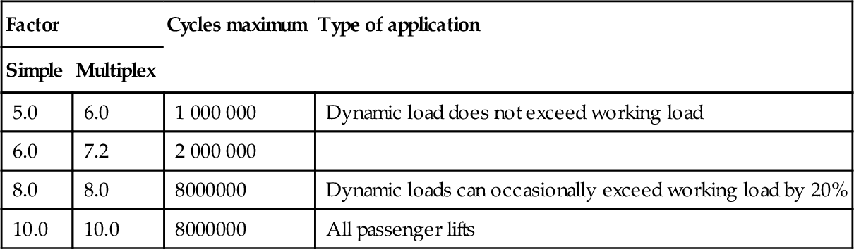
The table below gives a rough indication of life for various factors of safety.
| Factor | Cycles maximum | Type of application | |
| Simple | Multiplex | ||
| 5.0 | 6.0 | 1 000 000 | Dynamic load does not exceed working load |
| 6.0 | 7.2 | 2 000 000 | |
| 8.0 | 8.0 | 8000000 | Dynamic loads can occasionally exceed working load by 20% |
| 10.0 | 10.0 | 8000000 | All passenger lifts |
It should be noted that at factors below 8:1, bearing pressures increase above the maximum recommended, with the result that increased wear will arise unless special attention is taken with lubrication, for example:
• Higher performance lubricants.
• Better methods of applying lubrication.
Important note
For factors of 5:1 the resulting bearing pressure is 50% higher than recommended and chain working under these conditions will wear prematurely, whatever type of lubrication regime is used.
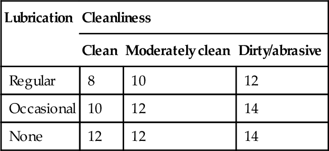
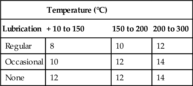
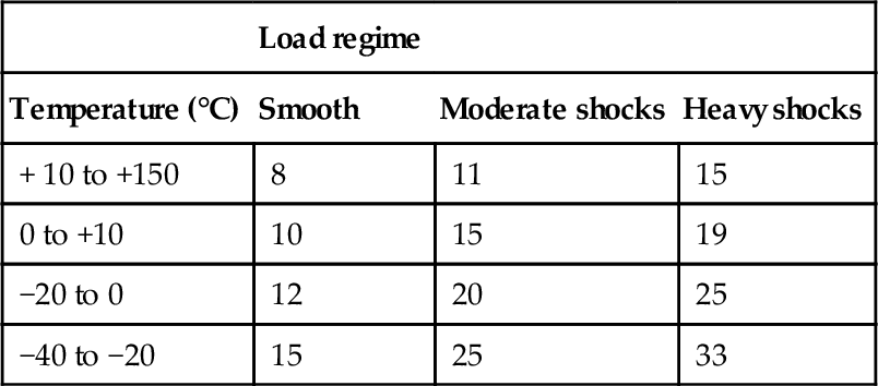
Harsh environments
In anything other than a clean and well lubricated environment, the factor of safety should be adjusted if some detriment to the working life of the chain is to be avoided. Low temperatures will also decrease working life, especially if shock loads are involved.
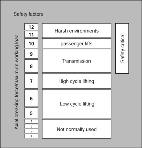
The following tables give a general guide to the appropriate safety factors for different applications for a target life of 8 000 000 cycles.
5.3.20 Chain extension
When designing lifting applications it can be useful to know how much a chain will extend under a given load.
The approximate elongation of a chain under a given load can be measured by using the following formulae:
![]()
• Duplex Chain
![]()
• Triplex Chain
![]()
where:
ΔL = change in chain length (mm)
L = original length of the chain (mm)
P = pitch of the chain (mm)
F1 = average load in the chain.
5.3.21 Matching of chain
Any application in which two or more strands of transmission chain are required to operate side by side in a common drive, or conveying arrangement, may involve the need for either pairing or matching. Such applications generally fall into one of the following categories:
Length matching for conveying and similar applications
Wherever length matching of transmission chain is necessary it is dealt with as follows:
• The chains are accurately measured in handling lengths between 3m and 8m as appropriate and then selected to provide a two (or more) strand drive having overall length uniformity within close limits. However, such length uniformity will not necessarily apply to any intermediate sections along the chains, but the actual length of all intermediate sections, both along and across the drive, will not vary more than our normal manufacturing limits. However, adapted transmission chains are usually manufactured to specific orders which are generally completed in one production run so that it is reasonable to assume that length differences of intermediate sections will be small.
• Chains are supplied in sets which are uniform in overall length within reasonably fine limits and will be within our normal manufacturing limits. It should be noted that chain sets supplied against different orders at different times may not have exactly the same lengths to those supplied originally, but will vary by no more than our normal tolerance of 0.0%, +0.15%.
Pitch matching transmission drive chains
Pitch matched chains are built up from shorter subsections (usually 300 to 600 mm lengths) which are first measured and then graded for length. All subsections in each grade are of closely similar length and those forming any one group across the set of chains are selected from the same length grade.
The requisite number of groups are then connected to form a pitch matched set of chains, or alternatively, if this is too long for convenient handling, a set of handling sections for customer to assemble as a final set of pitch matched chain. Suitable tags are fixed to the chains to ensure they are connected together in the correct sequence.
Identification of handling lengths
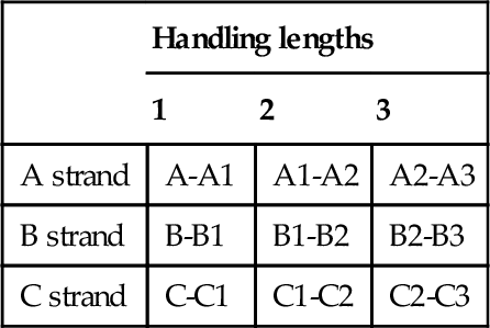
Long chains are made up in sections, each section being numbered on end links. Sections should be so joined up that end links with similar numbers are connected. Where chains are to run in sets of two or more strands, each strand is stamped on end links of each section with a letter, in addition to being numbered. Correct consecutive sections for each strand must be identified from the end links and joined up as indicated.
By these means, the actual length of any intermediate portion of one strand (as measured from any one pitch point to any other) will correspond closely with that of the transversely equivalent portion on the other strands, generally within 0.05 mm, depending on the chain pitch size.
Pitch matching adapted transmission chains (when attachments are fitted to chains)
With the sole exception of extended bearing pins, it is not possible to match the pitch of holes in attachments themselves to within very fine limits, due to the additional tolerances to be contended with (bending, holing, etc.).
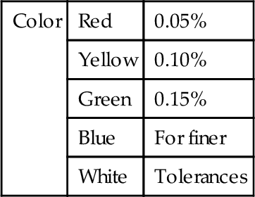
Colour coding
For customers who wish to match their chains, perhaps in order to fit special attachments in situ, Renold colour code short lengths of chain within specified tolerance bands. These will normally be red, yellow or green paint marks to indicate lower, mid and upper thirds of the tolerance band. For even finer tolerance bands additional colours can be used, but normally a maximum of five colours will be more than adequate.
5.3.22 To measure chain wear
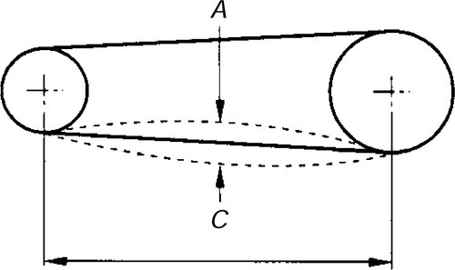
A direct measure of chain wear is the extension in excess of the nominal length of the chain. the chain wear can therefore be ascertained by length measurement in line with the instructions given below:
• Lay the chain, which should terminate at both ends with an inner link (part No 4), on a flat surface, and, after anchoring it at one end, attach to the other end a turnbuckle and a spring balance suitably anchored.
• Apply a tension load by means of the turnbuckle amounting to:
where P is the pitch in mm.
In the case of double pitch chains (e.g. chains having the same breaking load and twice the pitch) apply measuring loads as for the equivalent short pitch chains.
As an alternative, the chain may be hung vertically and the equivalent weight attached to the lower end.

• Measure length ‘M’ (see diagram above) in millimetres from which the percentage extension can be obtained from the following formula:
![]()
Where:
N = Number of pitches measured
P = Pitch
• As a general rule, the useful life of the chain is terminated and the chain should be replaced when extension reaches 2% (1% in the case of double pitch chains). For drives with no provision for adjustment, the rejection limit is lower, dependent on the speed and layout. A usual figure is between 0.7% and 1.0% extension.
Renold chain wear guide
A simple-to-use chain wear guide is available from Renold chain for most popular sizes of chain pitch. Please contact your Sales Office for details.
5.3.23 Repair and replacement
Sprockets
Examination of both flanks will give an indication of the amount of wear which has occurred. Under normal circumstances this will be evident as a polished worn strip about the pitch circle diameter of the sprocket tooth.
If the depth of this wear ‘X’ has reached an amount equal to 10% of the ‘Y’ dimension, then steps should be taken to replace the sprocket. Running new chain on sprockets having this amount of tooth wear will cause rapid chain wear.

It should be noted that in normal operating conditions, with correct lubrication the amount of wear ‘X’ will not occur until several chains have been used.
Chain
Chain repair should not as a rule be necessary. A correctly selected and maintained chain should gradually wear out over a period of time (approximately 15 000 h), but it should not fail. Please refer to the Installation and Maintenance section, which gives an indication of the service life remaining.
If a transmission chain sustains damage due to an overload, jam-up, or by riding over the sprocket teeth, it should be carefully removed from the drive and given a thorough visual examination. Remove the lubricating grease and oil to make the job easier.
Depending on the damage, it may be practicable to effect temporary repairs using replacement links. However, it is not a guarantee that the chain has not been over stressed and so made vulnerable to a future failure. The best policy, therefore, is to remove the source of trouble and fit a new chain. This should be done for the following reasons:
1. The cost of down time to the system or machine can often outweigh the cost of replacing the chain.
2. A new or even used portion of chain or joints assembled into the failed chain will cause whipping and load pulsation. This can, and probably will, produce rapid failure of the chain and will accelerate wear in both the chain and its sprockets.
If a chain has failed two or more times, it is certain the chain will fail again in time. If no replacement is immediately available, repair the chain, but replace it at the earliest opportunity.
5.3.24 Chain adjustment
To obtain full chain life, some form of chain adjustment must be provided, preferably by moving one of the shafts. If shaft movement is not possible, an adjustable jockey sprocket engaging with the unloaded strand of the chain is recommended. Generally the jockey should have the same number of teeth as the driver sprocket and care should be taken to ensure the speed does not exceed the maximum shown in the rating charts (see pages 437 and 438).
The chain should be adjusted regularly so that, with one strand tight, the slack strand can be moved a distance 'A' at the mid point (see diagram below). To cater for any eccentricities of mounting, the adjustment of the chain should be tried through a complete revolution of the large sprocket.
A= total movement
![]()
Where: K= 25 for smooth drives = 50 for shock drives
For vertical drives please consult the installation and maintenance section, which gives more details on chain adjustment.
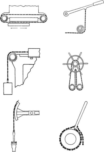
5.3.25 Design ideas
A variety of applications.
Conveying, indexing, lifting and pulling, power transmission and timing.
A variety of industries.
Aircraft, automotive, marine, mechanical handling, motorcycle, nuclear oilfield.
5.3.26 Table of PCD factors
To obtain PCD of any sprocket with 9 to 150 teeth, multiply chain pitch by appropriate factor.
For example, the PCD of a 38T sprocket of 3/4in. (19.05 mm) pitch = 19.05 × 12.110 = 230.70 mm.
| No. of teeth | PCD factor |
| 9 | 2.2 |
| 10 | 3.3 |
| 11 | 3.3 |
| 12 | 3.3 |
| 13 | 4.4 |
| 14 | 4.4 |
| 15 | 4.4 |
| 16 | 5.5 |
| 17 | 5.5 |
| 18 | 5.5 |
| 19 | 6.6 |
| 20 | 6.6 |
| 21 | 6.6 |
| 22 | 7.7 |
| 23 | 7.7 |
| 24 | 7.7 |
| 25 | 7.7 |
| 26 | 8.8 |
| 27 | 8.8 |
| 28 | 8.8 |
| 29 | 9.9 |
| 30 | 9.9 |
| 31 | 9.9 |
| 32 | 10.10 |
| 33 | 10.10 |
| 34 | 10.10 |
| 35 | 11.11 |
| 36 | 11.11 |
| 37 | 11.11 |
| 38 | 12.12 |
| 39 | 12.12 |
| 40 | 12.12 |
| 41 | 13.13 |
| 42 | 13.13 |
| 43 | 13.13 |
| 44 | 14.14 |
| 45 | 14.14 |
| 46 | 14.14 |
| 47 | 14.14 |
| 48 | 15.15 |
| 49 | 15.15 |
| 50 | 15.15 |
| 51 | 16.16 |
| 52 | 16.16 |
| 53 | 16.16 |
| 54 | 17.17 |
| 55 | 17.17 |
| 56 | 17.17 |
| 57 | 18.18 |
| 58 | 18.18 |
| 59 | 18.18 |
| 60 | 19.19 |
| 61 | 19.19 |
| 62 | 19.19 |
| 63 | 20.20 |
| 64 | 20.20 |
| 65 | 20.20 |
| 66 | 21.21 |
| 67 | 21.21 |
| 68 | 21.21 |
| 69 | 21.21 |
| 70 | 22.22 |
| 71 | 22.22 |
| 72 | 22.22 |
| 73 | 23.23 |
| 74 | 23.23 |
| 75 | 23.23 |
| 76 | 24.24 |
| 77 | 24.24 |
| 78 | 24.24 |
| 79 | 25.25 |
| 80 | 25.25 |
| 81 | 25.25 |
| 82 | 26.26 |
| 83 | 26.26 |
| 84 | 26.26 |
| 85 | 27.27 |
| 86 | 27.27 |
| 87 | 27.27 |
| 88 | 28.28 |
| 89 | 28.28 |
| 90 | 28.28 |
| 91 | 28.28 |
| 92 | 29.29 |
| 93 | 29.29 |
| 94 | 29.29 |
| 95 | 30.30 |
| 96 | 30.30 |
| 97 | 30.30 |
| 98 | 31.31 |
| 99 | 31.31 |
| 100 | 31.31 |
| 101 | 32.32 |
| 102 | 32.32 |
| 103 | 32.32 |
| 104 | 33.33 |
| 105 | 33.33 |
| 106 | 33.33 |
| 107 | 34.34 |
| 108 | 34.34 |
| 109 | 34.34 |
| 110 | 35.35 |
| 111 | 35.35 |
| 112 | 35.35 |
| 113 | 35.35 |
| 114 | 36.36 |
| 115 | 36.36 |
| 116 | 36.36 |
| 117 | 37.37 |
| 118 | 37.37 |
| 119 | 37.37 |
| 120 | 38.38 |
| 121 | 38.38 |
| 122 | 38.38 |
| 123 | 39.39 |
| 124 | 39.39 |
| 125 | 39.39 |
| 126 | 40.40 |
| 127 | 40.40 |
| 128 | 40.40 |
| 129 | 41.41 |
| 130 | 41.41 |
| 131 | 41.41 |
| 132 | 42.42 |
| 133 | 42.42 |
| 134 | 42.42 |
| 135 | 42.42 |
| 136 | 43.43 |
| 137 | 43.43 |
| 138 | 43.43 |
| 139 | 44.44 |
| 140 | 44.44 |
| 141 | 44.44 |
| 142 | 45.45 |
| 143 | 45.45 |
| 144 | 45.45 |
| 145 | 46.46 |
| 146 | 46.46 |
| 147 | 46.46 |
| 148 | 47.47 |
| 149 | 47.47 |
| 150 | 47.47 |
5.3.27 Simple point to point drives: Example one
The following worked examples give simple step-by-step guidance on selecting various types of chain drive systems. Renold technical staff are available to advise on any chain selection problems.
For details of transmission equations see page 442.
Example one: Rotary pump drive
Given:
• Power absorbed 7.5 kW
• Driver Electric motor at 1440 rev/min
• ConstraintsCentre distance approximately 458 mm Adjustment by shaft movement
Selection parameters
• No polygonal effect
• Satisfactory for smooth drives
Calculate the drive ratio as follows:
![]()
Therefore the driven number of teeth
![]()
Selection factors
Application factor f1 = 1 (driver and driven sprockets smooth running):
![]()
Select chain
The chain can now be selected using charts 3 and 4 and cross referencing power to speed, giving the following possibilities:
| 0.5" BS Simplex | (approximately 81% of rated capacity) |
| 0.375" BS Duplex | (approximately 98% of rated capacity) |
| 0.5" ANSI Simplex | (approximately 83% of rated capacity) |
| 0.375" ANSI Duplex | (approximately 84% of rated capacity) |
0.375" ANSI Duplex chain is unsuitable as it is a bush chain.
Note: The approximation percentage of rated capacity is calculated by dividing the selection power at 1440 rev/min by the chains maximum capacity at 1440 rev/min.
For this example we will choose 0.5" European Simplex.
Installation parameters
Lubrication European chain rating chart (see page 441) clearly indicates the chain needs oilbath lubrication. The chain will need to be enclosed and run in a sump of oil.
We now calculate the chain length:

Round up to the nearest number of even pitches, that is, 122.
Centre distance calculation
The centre distance of the drive can now be calculated using the formula shown below:
Adjustment
Provide for chain wear of 2% or two pitches, whichever is smaller, in this case, (122 × 1.02) − 122 = 2.44 pitches.
Therefore use two pitches and recalculate using:
L = 124 in the above equation. This gives
C = 471.7 mm
that is, total adjustment of 13.1 mm.
Note that in practice, some negative adjustment will facilitate assembly and will be essential if it is intended to assemble chain which is pre-joined into an endless loop.
Other data
![]()
Note the load in the chain due to centripetal acceleration becomes much more significant at higher speeds since the square of the chain velocity is in the equation:
Chain axial breaking force = 19 000 N

5.3.28 Simple point to point drives: Example two
The following worked examples give simple step-by-step guidance on selecting various types of chain drive systems. Renold technical staff are available to advise on any chain selection problems.
For details of transmission equations see page 442.
Example two: 4-cylinder compressor
Given:
• Power absorbed 250 kW
• DriverElectric motor at 960 rpm
• Constraints Centre distance approx. 1500 mm
Selection parameters
Use a 25T sprocket for an impulsive drive (see page 434 selection of drive ratio and sprockets:
Selection factors
Application factor f1 = 1.5 (driver and driven sprocket medium impulsive):
![]()
Select chain
The chain can now be selected using European Chain Rating Chart (see page 441) by cross referencing the power (285 kW on the vertical axis) and speed (960 rev/min on the horizontal axis).
Two matched strands of 1.25" pitch European triplex chains could be used with a heat treated 25 tooth steel driver and a 95 tooth driven sprocket to give a drive ratio of 3.8:1.
Installation parameters
Lubrication European chain rating chart (see page 441) clearly shows that an oilstream system is required on this drive. The chain should run in an enclosure with a pump and sump arrangement.
We will now calculate the chain length:
Round up to the nearest number of even pitches that is, 158.
Centre distance calculation
The centre distance of the drive can now be calculated using the standard formula below: = 1514.44 mm

Adjustment
Multi-shaftdrives
Shafts in series
This arrangement shows the driving of live roller conveyors.
The choice of the chain is based on the slipping torque between the rollers and the material to be transported. The safety factor to be applied for this type of drive is typically:
Safety factor= 5 for one direction drives
Safety factor= 8 for reversible drives
Every roller except the last comprises two simple sprockets, or one special sprocket to be used with two simple chains. At low speeds or in reversible drives, sprockets with hardened teeth should be used.
Roller conveyors with less than 10 rollers can be driven from one of the ends of the track. When the number of rollers is higher, it is recommended that the driving arrangement is in the middle of the conveyor in order to have a better distribution of the power and the highest overall efficiency.
If we assume that a drive operating under ideal conditions such as a clean environment and correct lubrication achieves an efficiency of R%, then the overall efficiency of a roller conveyor with X rollers will be:
![]()
If the individual drive efficiency R is equal to 98%, then the drive of a roller conveyor with 30 rollers will therefore only have an overall efficiency of 55%.
Consequently, it is recommended that no more than 30 rollers per drive are used. For roller conveyors with more than 30 rollers, use multiple drives.
The drive should be able to develop a torque corresponding to the slipping torque of the loaded rollers.
5.3.29 Simple point to point drives: Example three
The following worked examples give simple step-by-step guidance on selecting various types of chain drive systems. Renold technical staff are available to advise on any chain selection problems.
For details of transmission equations see page 438.
Example three
Given:
• Moving a stack of steel plates.
• 20 rollers with a diameter of 150 mm.
• Shafts with a diameter of 60 mm on ball bearings.
• Weight of one roller 1900 N.
• There are two stacks on the conveyor at any one time.
• One stack weighs 17 500 N with a length of 1500 mm.
• Total nett load: 35 000 N (two stacks).
• Centre distance of the rollers: 300 mm.
• Linear speed: 15 m/min.
• PCD of the sprockets: 140 mm.
• Impulsive load: 30 starts per hour, in one direction.
Assumptions
• A drive is placed in the middle with 10 rollers on each side.
• The rolling resistance of the rollers is 0.05.
• The friction resistance between the rollers and the load is 0.25.
• The efficiency per drive is 98%.
Selection calculations
Every stack of steel is 17 500 N and is conveyed by:
![]()
or 10 rollers for the total nett load.
If a nett load of 35 000 N is added to the total weight of 10 bearing rollers (19 000 N), then this gives a gross load of 54 000 N. The tangential force for 10 rollers is: 54000 × 0.05 = 2700 N and the corresponding torque is:
![]()
Note: where d =shaft diameter.
For each group of 10 rollers the efficiency will be:
![]()
The effective torque then becomes:
![]()
For sprockets with a pitch circle diameter of 140 mm, the pull in the chain will be:
![]()
The friction force for a friction coefficient of 0.25 is 35 000 × 0.25 = 8750 N.
The corresponding torque is equal to:
![]()
Note: Where d =radius of shaft.
The total drive torque is 656 + 81 = 737 Nm
The effective torque is therefore:
![]()
The pull in the chain then becomes:
![]()
Per drive we can now evaluate chain ISO 16B-1 or Renold chain 1 10088 running with two sprockets with 17 teeth and a pitch circle diameter of 138 mm.
In normal use:

When slipping they are:
The linear speed of the chain is:
![]()
Note: Where d1 = PCD of sprocket in metres.
For each group of 10 rollers the power is: ![]()
Under normal working conditions
when the rollers are slipping.
• Taking the efficiency of the gear until into account and adding a factor of 25% to this total power, 3.7 kW will be necessary.
Note: At higher linear speeds, we should also take into account other additional factors such as the moment of inertia of the rollers and the power needed to accelerate the various components of the system.
Shafts in parallel
Drives of this type will only be used when:
• There is a steady load, preferably divided evenly over the sprocket system.
• At linear speeds not higher than 1.5 m/sec.
• It is driven in one direction only.
The efficiency of this driving method is higher than for the series drive because there is reduced tooth contact.
Every drive needs special attention with regard to the positioning of the driver sprocket, the jockey and the reversing pinions.
The layout of the sprockets, the support and the guidance of the chain determine to a large extent, the service life of the chain.
The chain in most cases is quite long and a good grip on the driver sprocket is only possible when a degree of pre-tensioning is applied. This should never exceed half the normal pulling load of the application.
The method of selection is the same as for that detailed under Shafts in Series.
Drives mounted as in bottom figure have an efficiency under normal conditions of:
• 89% with 10 rollers
• 84% with 15 rollers
• 79% with 20 rollers
• 75% with 25 rollers.
5.3.30 Safety warnings
Connecting links
No. 11 or 26 joints (slip fit) should not be used where high speed or arduous conditions are encountered. In these or equivalent circumstances where safety is essential, a riveting link No. 107 (interference fit) must be used.
Wherever possible, driver should have sufficient overall adjustment to ensure the use of an even number of pitches throughout the useful life of the chain. A cranked link joint (No. 12 or 30) should only be used as a last resource and restricted to light duty, non-critical applications.
Chainmaintenance
The following precautions must be taken before disconnecting and removing a chain from a drive prior to replacement, repair or length alteration.
1. Always isolate the power source from the drive or equipment.
2. Always wear safety glasses.
3. Always wear appropriate protective clothing, hats, gloves and safety shoes, as warranted by the circumstances.
4. Always ensure tools are in good working condition and used in the proper manner.
5. Always loosen tensioning devices.
6. Always support the chain to avoid sudden unexpected movement of chain or components.
7. Never attempt to disconnect or reconnect a chain unless the method of safe working is fully understood.
8. Make sure correct replacement parts are available before disconnecting the chain.
9. Always ensure that directions for current use of any tools is followed.
10. Never re-use individual components.
11. Never re-use a damaged chain or chain part.
12. On light duty drives where a spring clip (No. 26) is used, always ensurethat the clip is fitted correctly in relation to direction of travel.
For further information on:
• BS and ANSI products and dimensions,
• chain installation and maintenance,
• designer guide,
• industry applications.
Consult the web site of Renold Power Transmission Ltd. www.renold.com
See also their general catalogue obtainable from the address in Appendix 3.
5.4 Powertransmission:shafts
5.4.1 Square and rectangular parallel keys, metric series

| Shaft | Key | Keyway | ||||||||||||
| Nominal diameter (d) | (see section 5.4.2) section (b × h) width × thickness | Width (b) | Depth | Radius r | ||||||||||
| Nom. | Tolerance for class of fit | |||||||||||||
| Free | Normal | Close and interference | Shaft t1 | Hub t2 | ||||||||||
| Over | Incl. | Shaft (H9) | Hub (D10) | Shaft (N9) | Hub (Js9) | Shaft and hub (P9) | Nom. | Tol. | Nom. | Tol. | Max. | Min. | ||
| 6 | 8 | 2 × 2 | 2 | +0.025 | +0.060 | -0.004 | +0.012 | -0.006 | 1.2 | 10. | 0.16 | 0.08 | ||
| 8 | 10 | 3x3 | 3 | 0 | +0.020 | -0.029 | -0.012 | -0.031 | 1.8 | 1.4 | 0.16 | 0.08 | ||
| 10 | 12 | 4 × 4 | 4 | 2.5 | +0.1 | 1.8 | +0.1 | 0.16 | 0.08 | |||||
| 12 | 17 | 5 × 5 | 5 | +0.030 | +0.078 | 0 | +0.015 | -0.012 | 3.0 | 0 | 2.3 | 0 | 0.25 | 0.16 |
| 17 | 22 | 6 × 6 | 6 | 0 | +0.08 | -0.030 | -0.015 | -0.042 | 3.5 | 2.8 | 0.25 | 0.16 | ||
| 22 | 30 | 8 × 7 | 8 | +0.036 | +0.095 | 0 | +0.018 | -0.015 | 4.0 | +0.2 | 3.3 | +0.2 | 0.25 | 0.16 |
| 30 | 38 | 10 × 8 | 10 | 0 | +0.040 | -0.036 | -0.018 | -0.051 | 5.0 | 0 | 3.3 | 0 | 0.40 | 0.25 |
| 38 | 44 | 12 × 8 | 12 | 5.0 | 3.3 | 0.40 | 0.25 | |||||||
| 44 | 50 | 14 × 9 | 14 | +0.043 | +0.120 | 0 | +0.021 | -0.018 | 5.5 | 3.8 | 0.40 | 0.25 | ||
| 50 | 58 | 16 × 10 | 16 | 0 | +0.050 | -0.043 | -0.021 | -0.061 | 6.0 | +0.2 | 4.3 | +0.2 | 0.40 | 0.25 |
| 58 | 65 | 18 × 11 | 18 | 7.0 | 0 | 4.4 | 0 | 0.40 | 0.25 | |||||
| 65 | 75 | 20 × 12 | 20 | 7.5 | 4.9 | 0.60 | 0.40 | |||||||
| 75 | 85 | 22 × 14 | 22 | +0.052 | +0.149 | 0 | +0.026 | -0.022 | 9.0 | 5.4 | 0.60 | 0.40 | ||
| 85 | 95 | 25 × 14 | 25 | 0 | +0.065 | -0.052 | -0.026 | -0.074 | 9.0 | 5.4 | 0.60 | 0.40 | ||
| 95 | 110 | 28 × 16 | 28 | 10.0 | 6.4 | 0.60 | 0.40 | |||||||
| 110 | 130 | 32 × 18 | 32 | 11.0 | 7.4 | 0.60 | 0.40 | |||||||
| 130 | 150 | 36 × 20 | 36 | +0.062 | +0.180 | 0 | +0.031 | -0.025 | 12.0 | 8.4 | 1.00 | 0.70 | ||
| 150 | 170 | 40 × 22 | 40 | 0 | +0.080 | -0.062 | -0.031 | -0.088 | 13.0 | +0.3 | 9.4 | +0.3 | 1.00 | 0.70 |
| 170 | 200 | 45 × 25 | 45 | 13.0 | 0 | 10.4 | 0 | 1.00 | 0.70 | |||||
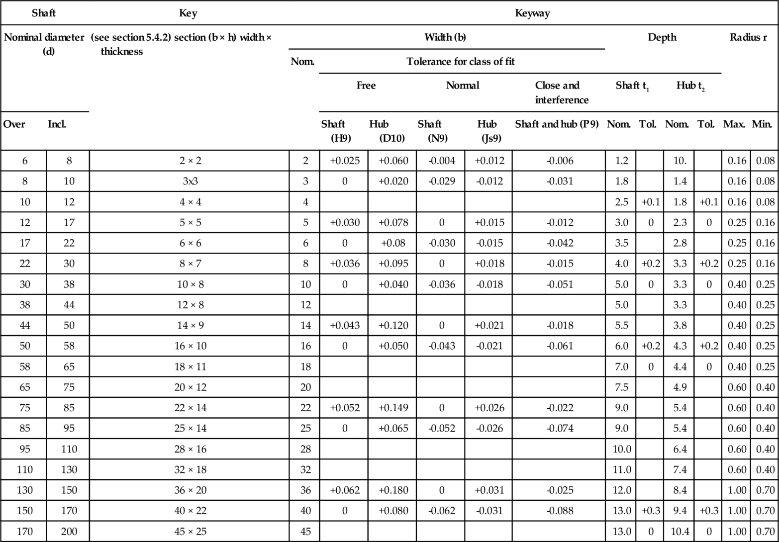
For full range and further information see BS 4235: Part 1: 1972.
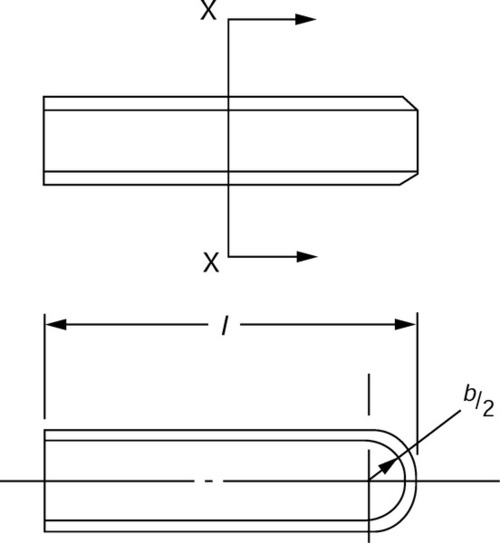
5.4.2 Dimensions and tolerances for square and rectangular parallel keys
Form A
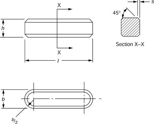
Form B
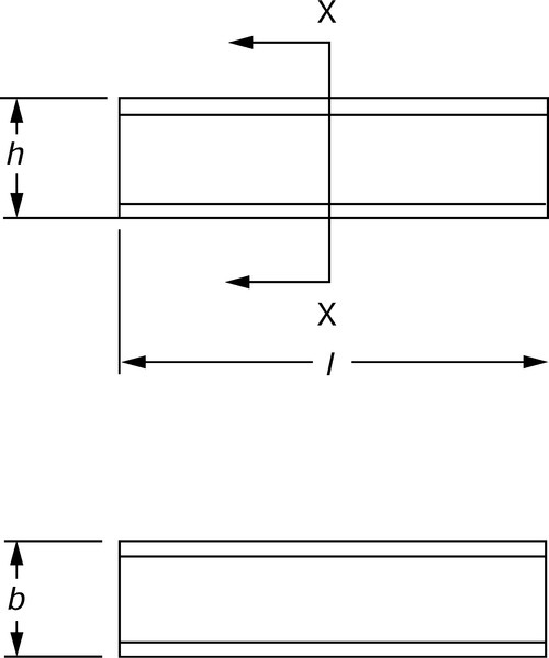
Form C
| Width (b) | Thickness (h) | Chamfer (s) | Range of lengths (/*) | ||||
| Nom. | Tol. (h9) | Nom. | Tol. (h9) | Min. | Max. | From | Incl. |
| 2 | 0 | 2 | 0 | 0.16 | 0.25 | 6 | 20 |
| 3 | −0.025 | 3 | −0.025 | 0.16 | 0.25 | 6 | 36 |
| 4 | 0 | 4 | 0 | 0.16 | 0.25 | 8 | 45 |
| 5 | −0.030 | 5 | −0.030 | 0.25 | 0.40 | 10 | 56 |
| 6 | 6 | 0.25 | 0.40 | 14 | 70 | ||
| 8 | 0 | 7 | Tol. (h11) | 0.25 | 0.40 | 18 | 90 |
| 10 | −0.036 | 8 | 0 | 0.40 | 0.60 | 22 | 110 |
| 12 | 8 | −0.090 | 0.40 | 0.60 | 28 | 140 | |
| 14 | 0 | 9 | 0.40 | 0.60 | 36 | 160 | |
| 16 | −0.043 | 10 | 0.40 | 0.60 | 45 | 180 | |
| 18 | 11 | 0.40 | 0.60 | 50 | 200 | ||
| 20 | 12 | 0.60 | 0.80 | 56 | 220 | ||
| 22 | 0 | 14 | 0 | 0.60 | 0.80 | 63 | 250 |
| 25 | −0.052 | 14 | −0.110 | 0.60 | 0.80 | 70 | 280 |
| 28 | 16 | 0.60 | 0.80 | 80 | 320 | ||
| 32 | 18 | 0.60 | 0.80 | 90 | 360 | ||
| 36 | 0 | 20 | 1.00 | 1.20 | 100 | 400 | |
| 40 | −0.062 | 22 | 0 | 1.00 | 1.20 | – | – |
| 45 | 25 | −0.130 | 1.00 | 1.20 | – | – | |
| 50 | 28 | 1.00 | 1.20 | – | – | ||
| 56 | 32 | 1.60 | 2.00 | – | – | ||
| 63 | 0 | 32 | 1.60 | 2.00 | – | – | |
| 70 | −0.074 | 36 | 0 | 1.60 | 2.00 | – | – |
| 80 | 40 | −0.160 | 2.50 | 3.00 | – | – | |
| 90 | 0 | 45 | 2.50 | 3.00 | – | – | |
| 100 | −0.087 | 50 | 2.50 | 3.00 | – | – | |
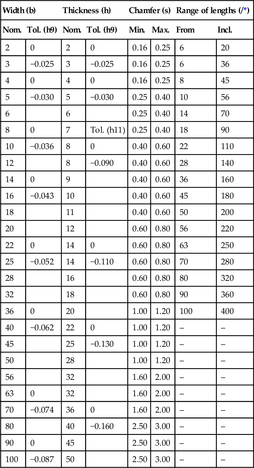
For full range and further information see BS 4235: Part 1: 1972.
* For preferred sizes see BS 4235: Table 9.
5.4.3 Square and rectangular taper keys, metric series

| Shaft | Key | Keyway | ||||||||
| Nominal diameter (d) | Section (b × h) width × thickness | Width (b), shaft and hub | Depth | Radius (r) | ||||||
| Shaft (t1) | Hub (t2) | |||||||||
| Over | Incl. | Nom. | Tol. (D10) | Nom. | Tol. | Nom. | Tol. | Max. | Min. | |
| 6 | 8 | 2 × 2 | 2 | +0.060 | 1.2 | 0.5 | 0.16 | 0.08 | ||
| 8 | 10 | 3 × 3 | 3 | +0.020 | 1.8 | +0.1 | 0.9 | +0.1 | 0.16 | 0.08 |
| 10 | 12 | 4 × 4 | 4 | +0.078 | 2.5 | 0 | 1.2 | 0 | 0.16 | 0.08 |
| 12 | 17 | 5 × 5 | 5 | +0.030 | 3.0 | 1.7 | 0.25 | 0.16 | ||
| 17 | 22 | 6 × 6 | 6 | 3.5 | 2.2 | 0.25 | 0.16 | |||
| 22 | 30 | 8 × 7 | 8 | +0.098 | 4.0 | 2.4 | 0.25 | 0.16 | ||
| 30 | 38 | 10 × 8 | 10 | +0.040 | 5.0 | 2.4 | 0.40 | 0.25 | ||
| 38 | 44 | 12 × 8 | 12 | 5.0 | 2.4 | 0.40 | 0.25 | |||
| 44 | 50 | 14 × 9 | 14 | +0.120 | 5.5 | 2.9 | 0.40 | 0.25 | ||
| 50 | 58 | 16 × 10 | 16 | +0.050 | 6.0 | +0.2 | 3.4 | +0.2 | 0.40 | 0.25 |
| 58 | 65 | 18 × 11 | 18 | 7.0 | 0 | 3.4 | 0 | 0.40 | 0.25 | |
| 65 | 75 | 20 × 12 | 20 | 7.5 | 3.9 | 0.60 | 0.40 | |||
| 75 | 85 | 22 × 14 | 22 | +0.149 | 9.0 | 4.4 | 0.60 | 0.40 | ||
| 85 | 95 | 25 × 14 | 25 | +0.065 | 9.0 | 4.4 | 0.60 | 0.40 | ||
| 95 | 110 | 28 × 16 | 28 | +0.065+0.149 | 10.0 | +0.2 | 5.4 | +0.2 | 0.60 | 0.40 |
| 110 | 130 | 32 × 18 | 32 | 11.0 | 0 | 6.4 | 0 | 0.60 | 0.70 | |
| 130 | 150 | 36 × 20 | 36 | +0.180 | 12.0 | 7.1 | 1.00 | 0.70 | ||
| 150 | 170 | 40 × 22 | 40 | +0.080 | 13.0 | 8.1 | 1.00 | 0.70 | ||
| 170 | 200 | 45 × 25 | 45 | 15.0 | 9.1 | 1.00 | 0.70 | |||
| 200 | 230 | 50 × 28 | 50 | 17.0 | +0.3 | 10.1 | +0.3 | 1.00 | 0.70 | |
| 230 | 260 | 56 × 32 | 56 | 20.0 | 0 | 11.1 | 0 | 1.60 | 1.20 | |
| 260 | 290 | 63 × 32 | 63 | +0.220 | 20.0 | 11.1 | 1.60 | 1.20 | ||
| 290 | 330 | 70 × 36 | 70 | +0.120 | 22.0 | 13.1 | 1.60 | 1.20 | ||
| 300 | 380 | 80 × 40 | 80 | 25.0 | 14.1 | 2.50 | 2.00 | |||
| 380 | 440 | 90 × 45 | 90 | +0.260 | 28.0 | 16.1 | 2.50 | 2.00 | ||
| 440 | 500 | 100 × 50 | 100 | +0.120 | 31.0 | 18.1 | 2.50 | 2.00 | ||
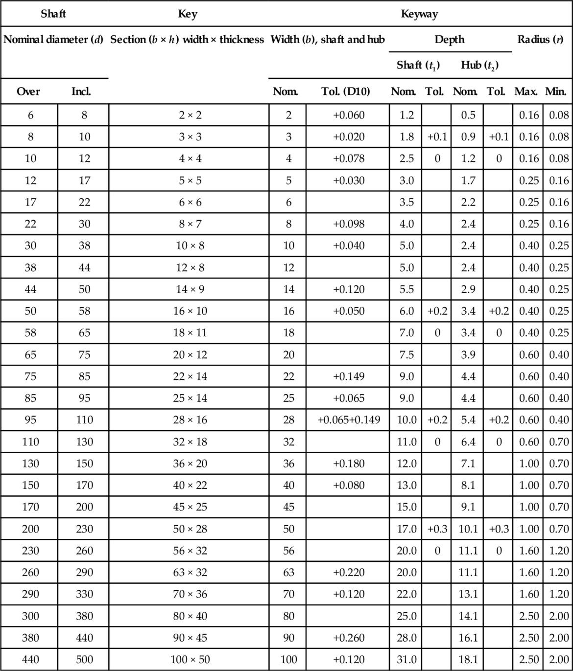
For full range and further information see BS 4235: Part 1: 1972.
5.4.4 Dimensions and tolerances for square and rectangular taper keys

| Width (b) | Thickness (h) | Chamfer (s) | Length (/*) | Gib-head nom’ (h1) | Radius | ||||
| Nom. | Tol. (h9) | Nom. | Tol. (h9) | Min. | Max. | From | Incl. | ||
| 2 | 0 | 2 | 0 | 0.16 | 0.25 | 6 | 20 | – | – |
| 3 | −0.025 | 3 | −0.025 | 0.16 | 0.25 | 6 | 36 | – | – |
| 4 | 0 | 4 | 0 | 0.16 | 0.25 | 8 | 45 | 7 | 0.25 |
| 5 | −0.030 | 5 | −0.030 | 0.25 | 0.40 | 10 | 56 | 8 | 0.25 |
| 6 | 6 | 0.25 | 0.40 | 14 | 70 | 10 | 0.25 | ||
| 8 | 0 | 7 | 0.25 | 0.40 | 18 | 90 | 11 | 1.5 | |
| 10 | −0.036 | 8 | Tol. (h11) | 0.40 | 0.60 | 22 | 110 | 12 | 1.5 |
| 12 | 8 | 0 | 0.40 | 0.60 | 28 | 140 | 12 | 1.5 | |
| 14 | 0 | 9 | −0.090 | 0.40 | 0.60 | 36 | 160 | 14 | 1.5 |
| 16 | −0.043 | 10 | 0.40 | 0.60 | 45 | 180 | 16 | 1.5 | |
| 18 | 11 | 0.40 | 0.60 | 50 | 200 | 18 | 1.5 | ||
| 20 | 12 | 0.60 | 0.80 | 56 | 220 | 20 | 1.5 | ||
| 22 | 0 | 14 | 0 | 0.60 | 0.80 | 63 | 250 | 22 | 1.5 |
| 25 | −0.052 | 14 | −0.110 | 0.60 | 0.80 | 70 | 280 | 22 | 1.5 |
| 28 | 16 | 0.60 | 0.80 | 80 | 320 | 25 | 1.5 | ||
| 32 | 18 | 0.60 | 0.80 | 90 | 360 | 28 | 1.5 | ||
| 36 | 0 | 20 | 1.00 | 1.20 | 100 | 400 | 32 | 1.5 | |
| 40 | −0.062 | 22 | 0 | 1.00 | 1.20 | – | – | 36 | 1.5 |
| 45 | 25 | −0.130 | 1.00 | 1.20 | – | – | 40 | 1.5 | |
| 50 | 28 | 1.00 | 1.20 | – | – | 45 | 1.5 | ||
| 56 | 32 | 1.60 | 2.00 | – | – | 50 | 1.5 | ||
| 63 | 0 | 32 | 1.60 | 2.00 | – | – | 50 | 1.5 | |
| 70 | −0.074 | 36 | 0 | 1.60 | 2.00 | – | – | 56 | 1.5 |
| 80 | 40 | −0.160 | 2.50 | 3.00 | – | – | 63 | 1.5 | |
| 90 | 0 | 45 | 2.50 | 3.00 | – | – | 70 | 1.5 | |
| 100 | −0.087 | 50 | 2.50 | 3.00 | – | – | 80 | 1.5 | |
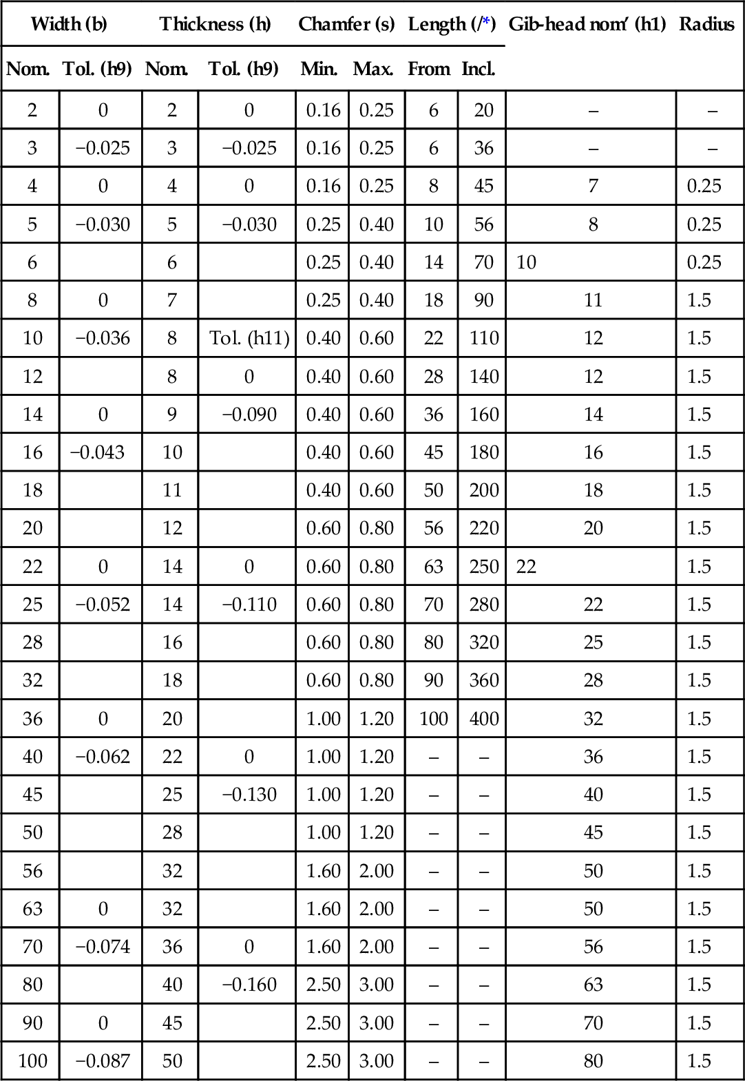
For full range and further information see BS 4235: Part 1: 1972.
* For preferred lengths see BS 4235: Part 1: Table 9.
5.4.5 Woodruff keys and keyways, metric series
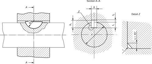
| Key size of normal for b x h1 x D or equivalent Whitney form | Width (b) | Depth | Radius (r) | |||||||
| Nom. | Tolerance | Shaft (t1) | Hub (t2) | |||||||
| Normal fit | Close fit | |||||||||
| Shaft (N9) | Hub (Js9) | Shaft and hub (P9) | Nom. | Tol. | Nom. | Tol. | Max. | Min. | ||
| 1.0 x 1.4 x 4 | 1.0 | 1.0 | 0.6 | 0.16 | 0.08 | |||||
| 1.5 x 2.6 x 7 | 1.5 | 2.0 | +0.1 | 0.8 | 0.16 | 0.08 | ||||
| 2.0 x 2.6 x 7 | 2.0 | - 0.004 | +0.012 | -0.006 | 1.8 | 0 | 1.0 | 0.16 | 0.08 | |
| 2.0 x 3.7 x 10 | 2.0 | -0.029 | -0.012 | -0.031 | 2.9 | 1.0 | 0.16 | 0.08 | ||
| 2.5 x 3.7 x 10 | 2.5 | 2.7 | 1.2 | +0.1 | 0.16 | 0.08 | ||||
| 3.0 x 5.0 x 13 | 3.0 | 3.8 | 1.4 | 0 | 0.16 | 0.08 | ||||
| 3.0 x 6.5 x 16 | 3.0 | 5.3 | 1.4 | 0.16 | 0.08 | |||||
| 4.0 x 6.5 x 16 | 4.0 | 5.0 | +0.2 | 1.8 | 0.25 | 0.16 | ||||
| 4.0 x 7.5 x 19 | 4.0 | 6.0 | 0 | 1.8 | 0.25 | 0.16 | ||||
| 5.0 x 6.5 x 16 | 5.0 | 4.5 | 2.3 | 0.25 | 0.16 | |||||
| 5.0 x 7.5 x 19 | 5.0 | 0 | +0.015 | -0.012 | 5.5 | 2.3 | 0.25 | 0.16 | ||
| 5.0 x 9.0 x 22 | 5.0 | -0.030 | -0.015 | - 0.042 | 7.0 | 2.3 | 0.25 | 0.16 | ||
| 6.0 x 9.0 x 22 | 6.0 | 6.5 | +0.3 | 2.8 | 0.25 | 0.16 | ||||
| 6.0 x 11.0 x 28 | 6.0 | 7.5 | 0 | 2.8 | +0.2 | 0.25 | 0.16 | |||
| 8.0 x 11.0 x 28 | 8.0 | 0 | +0.018 | -0.015 | 8.0 | 3.3 | 0 | 0.40 | 0.25 | |
| 10.0 x 13.0 x 32 | 10.0 | -0.036 | -0.018 | -0.051 | 10.0 | 3.3 | 0.40 | 0.25 | ||

For further information see BS 4235: Part 2: 1977.
5.4.6 Dimensions and tolerances for Woodruff Keys
Normalform
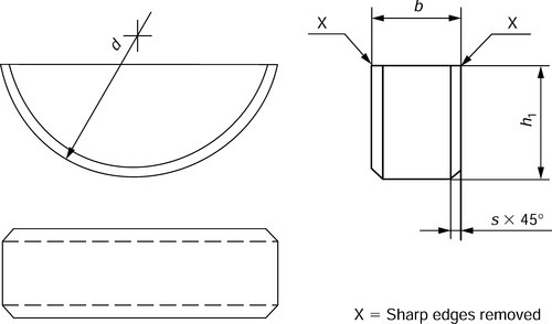
Whitney form
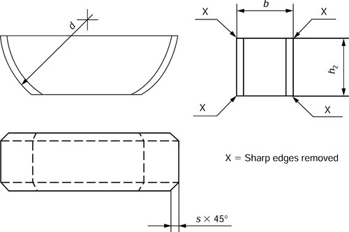
| Width b Nom. | Tol. (h9)* | Height (h1) | Diameter (d) | Chamfer (s) | |||
| Nom. | Tol. (h11) | Nom. | Tol. (h12) | Min. | Max. | ||
| 0 | |||||||
| 1.0 | 1.4 | 0 | 4 | −0.120 | 0.16 | 0.25 | |
| 1.5 | 2.6 | −0.060 | 7 | 0.16 | 0.25 | ||
| 2.0 | 0 | 2.6 | 7 | 0 | 0.16 | 0.25 | |
| 2.0 | −0.025 | 3.7 | 0 | 10 | −0.150 | 0.16 | 0.25 |
| 2.5 | 3.7 | −0.075 | 10 | 0.16 | 0.25 | ||
| 3.0 | 5.0 | 13 | 0 | 0.16 | 0.25 | ||
| 3.0 | 6.5 | 16 | −0.180 | 0.16 | 0.25 | ||
| 4.0 | 6.5 | 16 | 0.25 | 0.40 | |||
| 4.0 | 7.5 | 19 | 0 | 0.25 | 0.40 | ||
| −0.210 | |||||||
| 0 | |||||||
| 5.0 | 6.5 | 0 | 16 | −0.180 | 0.25 | 0.40 | |
| 5.0 | 0 | 7.5 | −0.090 | 19 | 0.25 | 0.40 | |
| 5.0 | −0.030 | 9.0 | 22 | 0 | 0.25 | 0.40 | |
| 6.0 | 9.0 | 22 | −0.210 | 0.25 | 0.40 | ||
| 6.0 | 10.0 | 25 | 0.25 | 0.40 | |||
| 8.0 | 0 | 11.0 | 0 | 28 | 0.40 | 0.60 | |
| 10.0 | −0.036 | 13.0 | −0.110 | 32 | 0 | 0.40 | 0.60 |
| −0.250 | |||||||
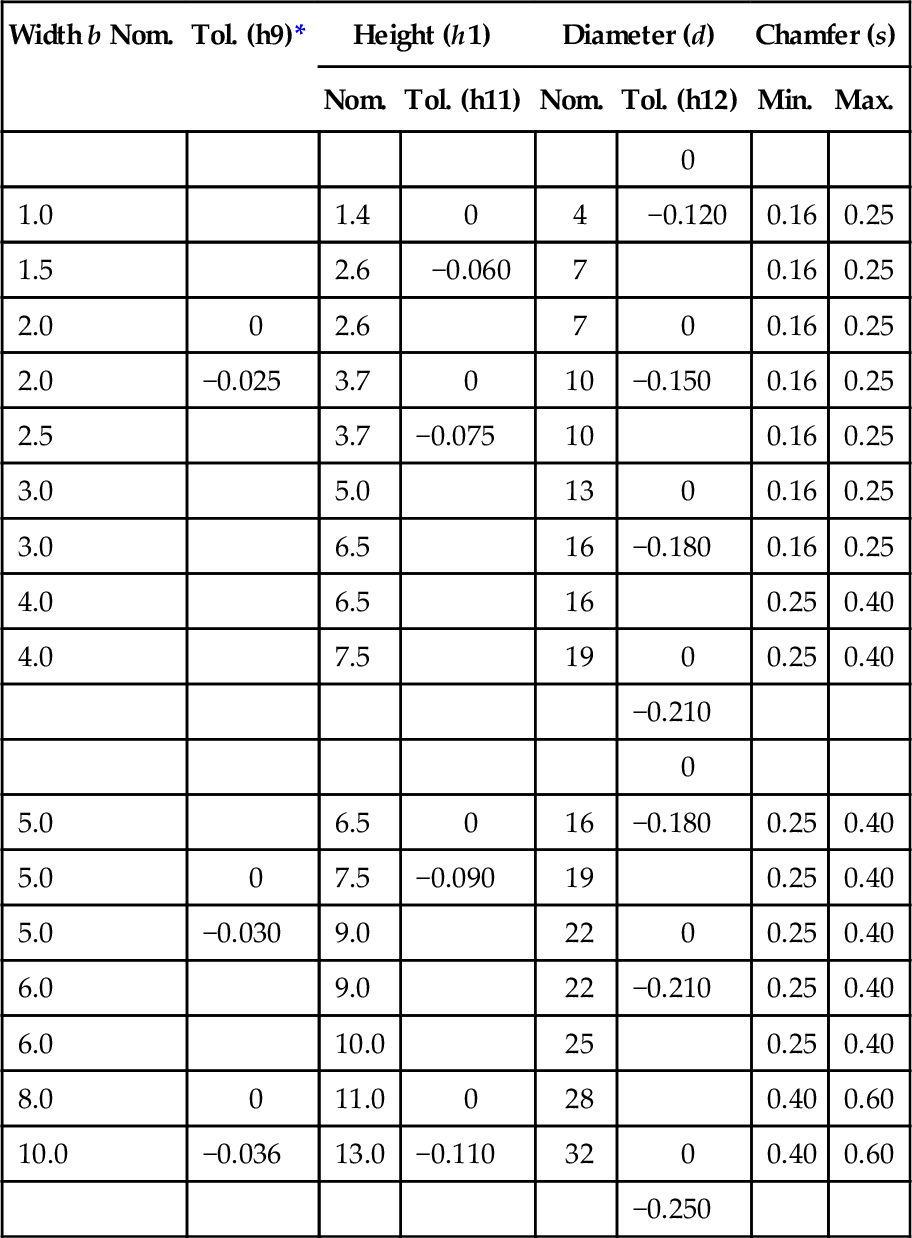
For further information see BS 4235: Part 2: 1977.
* A tolerance closer than h9 may be adopted subject to agreement between interested parties.
Note: The Whitney form should only be adopted by agreement between the interested parties. In this case h2 of the Whitney form key shall equal 0.8 times the height h of the normal form Woodruff key, that is, h2 = 0.8h1. The calculated values shall be rounded off to the nearest 0.1 mm.
5.4.7 Shaft ends types:general relationships

5.4.8 Dimensions and tolerances of cylindrical shaft ends, long and short series

Detail X: undercut grooves for tool relief and blendina radii are still under consideration in ISO. Details are not yet available.
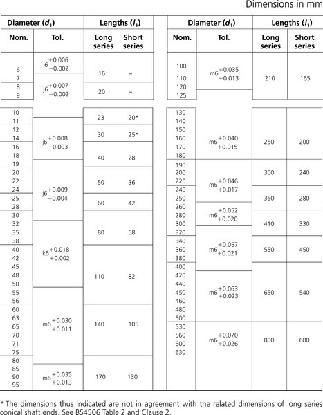

5.4.9 Dimensions of conical shaft ends with parallel keys, long series
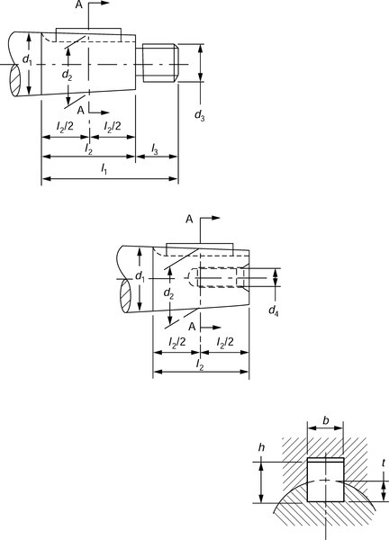
Keyway may have forms other than shown.
Conicity of 1:10 corresponds to (d1−d2)/(l2/2) = 1/10.
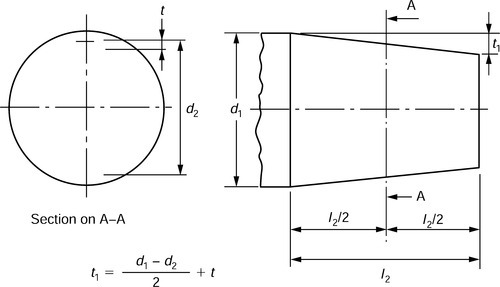
Dimensions in mm
| Diameter (d1) | Length | Key and keyway | External thread (d3) | Internal thread (d4) | |||||
| l1 | l2 | l3 | d2 | b × h | t | t1 | |||
| 6 | 16 | 10 | 6 | 5.5 | – | – | – | M4 × 0.7 | – |
| 7 | 6.5 | – | – | – | M4 × 0.7 | – | |||
| 8 | 20 | 12 | 8 | 7.4 | – | – | – | M6 × 1 | – |
| 9 | 8.4 | – | – | – | M6 × 1 | – | |||
| 10 | 23 | 15* | 8 | 9.25 | – | – | – | M6 × 1 | – |
| 11 | 10.25 | 2 × 2 | 1.2 | 1.6 | M6 × 1 | – | |||
| 12 | 30 | 18* | 12 | 11.1 | 2 × 2 | 1.2 | 1.7 | M8 × 1 | M4 × 0.7 |
| 14 | 13.1 | 3 × 3 | 1.8 | 2.3 | M8 × 1 | M4 × 0.7 | |||
| 16 | 40 | 28 | 12 | 14.6 | 3 × 3 | 1.8 | 2.5 | M10 × 1.25 | M4 × 0.7 |
| 18 | 16.6 | 4 × 4 | 2.5 | 3.2 | M10 × 1.25 | M5 × 0.8 | |||
| 19 | 17.6 | 4 × 4 | 2.5 | 3.2 | M10 × 1.25 | M5 × 0.8 | |||
| 20 | 50 | 36 | 14 | 18.2 | 4 × 4 | 2.5 | 3.4 | M12 × 1.25 | M6 × 1 |
| 22 | 20.2 | 4 × 4 | 2.5 | 3.4 | M12 × 1.25 | M6 × 1 | |||
| 24 | 22.2 | 5 × 5 | 3.0 | 3.9 | M12 × 1.25 | M6 × 1 | |||
| 25 | 60 | 42 | 18 | 22.9 | 5 × 5 | 3.0 | 4.1 | M16 × 1.5 | M8 × 1.25 |
| 28 | 25.9 | 5 × 5 | 3.0 | 4.1 | M16 × 1.5 | M8 × 1.25 | |||
| 30 | 80 | 58 | 22 | 27.1 | 5 × 5 | 3.0 | 4.5 | M20 × 1.5 | M10 × 1.5 |
| 32 | 29.1 | 6 × 6 | 3.5 | 5.0 | M20 × 1.5 | M10 × 1.5 | |||
| 35 | 32.1 | 6 × 6 | 3.5 | 5.0 | M20 × 1.5 | M10 × 1.5 | |||
| 38 | 35.1 | 6 × 6 | 3.5 | 5.0 | M24 × 2.0 | M12 × 1.75 | |||
| 40 | 110 | 82 | 28 | 35.9 | 10 × 8 | 5.0 | 7.1 | M24 × 2.0 | M12 × 1.75 |
| 42 | 37.9 | 10 × 8 | 5.0 | 7.1 | M24 × 2.0 | M12 × 1.75 | |||
| 45 | 40.9 | 12 × 8 | 5.0 | 7.1 | M30 × 2.0 | M16 × 2.0 | |||
| 48 | 43.9 | 12 × 8 | 5.0 | 7.1 | M30 × 2.5 | M16 × 2.0 | |||
| 50 | 45.9 | 12 × 8 | 5.0 | 7.1 | M36 × 3.0 | M16 × 2.0 | |||
| 55 | 50.9 | 14 × 9 | 5.5 | 7.6 | M36 × 3.0 | M20 × 2.5 | |||
| 56 | 51.9 | 14 × 9 | 5.5 | 7.6 | M36 × 3.0 | M20 × 2.5 | |||
| 60 | 140 | 105 | 35 | 54.75 | 16 × 10 | 6.0 | 8.6 | M42 × 3.0 | M20 × 2.5 |
| 63 | 57.75 | 16 × 10 | 6.0 | 8.6 | M42 × 3.0 | M20 × 2.5 | |||
| 65 | 59.75 | 16 × 10 | 6.0 | 8.6 | M42 × 3.0 | M20 × 2.5 | |||
| 70 | 64.75 | 18 × 11 | 7.0 | 9.6 | M48 × 3.0 | M24 × 3.0 | |||
| 71 | 65.75 | 18 × 11 | 7.0 | 9.6 | M48 × 3.0 | M24 × 3.0 | |||
| 75 | 69.75 | 18 × 11 | 7.0 | 9.6 | M48 × 3.0 | M24 × 3.0 | |||
| 80 | 170 | 130 | 40 | 73.50 | 20 × 12 | 7.5 | 10.8 | M56 × 4.0 | M30 × 3.5 |
| 85 | 78.50 | 20 × 12 | 7.5 | 10.8 | M56 × 4.0 | M30 × 3.5 | |||
| 90 | 83.50 | 22 × 14 | 9.0 | 12.3 | M64 × 4.0 | M30 × 3.5 | |||
| 95 | 88.50 | 22 × 14 | 9.0 | 12.3 | M64 × 4.0 | M36 × 4.0 | |||
| 100 | 210 | 165 | 45 | 91.75 | 25 × 14 | 9.0 | 13.1 | M72 × 4.0 | M36 × 4.0 |
| 110 | 101.75 | 25 × 14 | 9.0 | 13.1 | M80 × 4.0 | M42 × 4.5 | |||
| 120 | 111.75 | 28 × 16 | 10.0 | 14.1 | M90 × 4.0 | M42 × 4.5 | |||
| 125 | 116.75 | 28 × 16 | 10.0 | 14.1 | M90 × 4.0 | M48 × 5.0 | |||
| 130 | 250 | 200 | 50 | 120.0 | 28 × 16 | 10.0 | 15.0 | M100 × 4.0 | – |
| 140 | 130.0 | 32 × 18 | 11.0 | 16.0 | M100 × 4.0 | – | |||
| 150 | 140.0 | 32 × 18 | 11.0 | 16.0 | M110 × 4.0 | – | |||
| 160 | 300 | 240 | 60 | 148.0 | 35 × 20 | 12.0 | 18.0 | M125 × 4.0 | – |
| 170 | 158.0 | 36 × 20 | 12.0 | 18.0 | M125 × 4.0 | – | |||
| 180 | 168.0 | 40 × 22 | 13.0 | 19.0 | M140 × 6.0 | – | |||
| 190 | 350 | 280 | 70 | 176.0 | 40 × 22 | 13.0 | 20.0 | M140 × 6.0 | – |
| 200 | 186.0 | 40 × 22 | 13.0 | 20.0 | M160 × 6.0 | – | |||
| 220 | 206.0 | 45 × 25 | 15.0 | 22.0 | M160 × 6.0 | – | |||
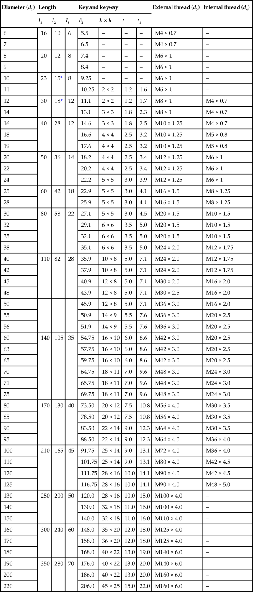
For further information see BS 4506.
* The dimensions thus indicated are not in agreement with the related dimensions for long series conical shaft ends. See BS 4506: Table 2 and Clause 2
5.4.10 Dimensions of conical shaft ends with diameters above 220 mm with the keyway parallel to the shaft surface, long series

Conicity of 1:10 corresponds to (d1−d2)/(l2/2) = 1/10.
| Diameter (d1) | Length | Key and keyway | External thread(d3) | ||||
| (l1) | (l2) | (l3) | (d2) | b × h | t | ||
| 240 | 223.5 | 50 × 28 | 17 | M180 × 6 | |||
| 250 | 410 | 330 | 80 | 233.5 | 50 × 28 | 17 | M180 × 6 |
| 260 | 243.5 | 50 × 28 | 17 | M200 × 6 | |||
| 280 | 261.0 | 56 × 32 | 20 | M220 × 6 | |||
| 300 | 470 | 380 | 90 | 281.0 | 63 × 32 | 20 | M220 × 6 |
| 320 | 301.0 | 63 × 32 | 20 | M250 × 6 | |||
| 340 | 317.5 | 70 × 36 | 22 | M280 × 6 | |||
| 360 | 550 | 450 | 100 | 337.5 | 70 × 36 | 22 | M280 × 6 |
| 380 | 357.5 | 70 × 36 | 22 | M300 × 6 | |||
| 400 | 373.0 | 80 × 40 | 25 | M320 × 6 | |||
| 420 | 393.0 | 80 × 40 | 25 | M320 × 6 | |||
| 440 | 413.0 | 80 × 40 | 25 | M350 × 6 | |||
| 450 | 650 | 540 | 110 | 423.0 | 90 × 45 | 28 | M350 × 6 |
| 460 | 433.0 | 90 × 45 | 28 | M380 × 6 | |||
| 480 | 453.0 | 90 × 45 | 28 | M380 × 6 | |||
| 500 | 473.0 | 90 × 45 | 28 | M420 × 6 | |||
| 530 | 496.0 | 100 × 50 | 31 | M420 × 6 | |||
| 560 | 800 | 680 | 120 | 526.0 | 100 × 50 | 31 | M450 × 6 |
| 600 | 566.0 | 100 × 50 | 31 | M500 × 6 | |||
| 630 | 596.0 | 100 × 50 | 31 | M550 × 6 | |||
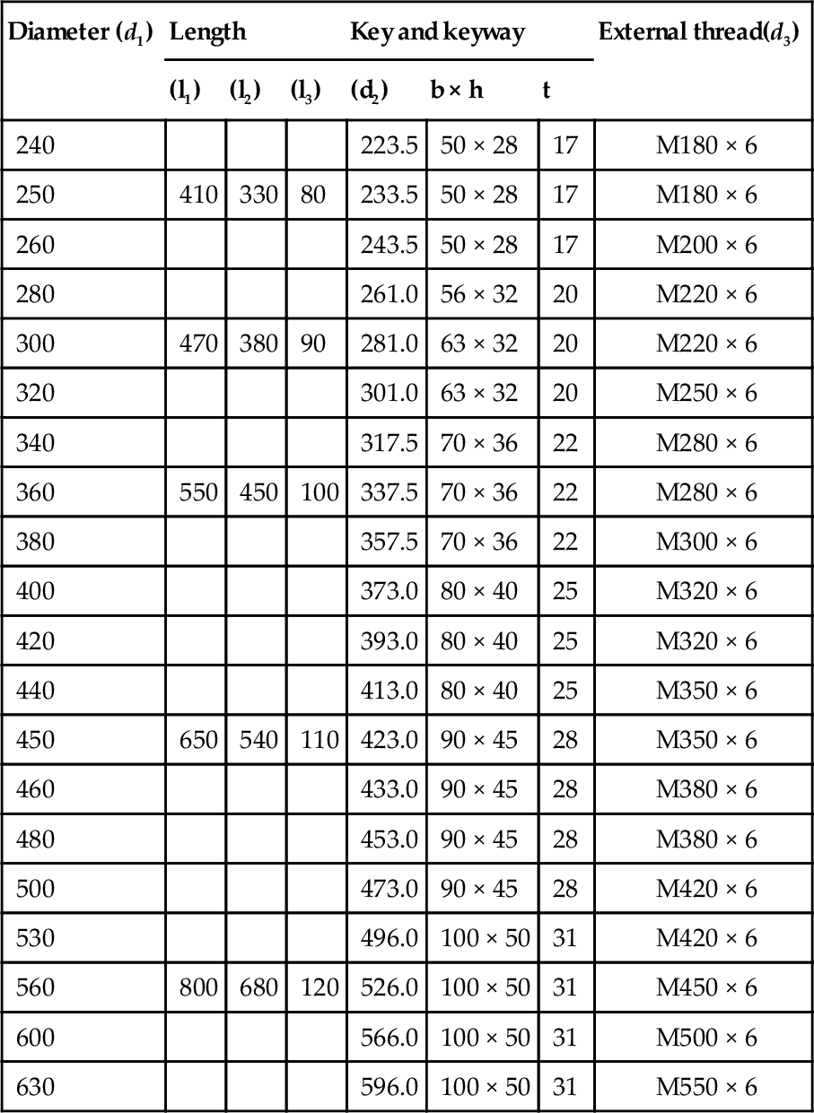
For further information see BS 4506.