
4.2 Riveted joints
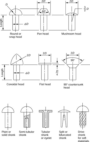
4.2.1 Typical rivet heads and shanks
4.2.2 Typical riveted lap joints
Single row lap joint

Double row (chain) lap joint

Double row (zigzag) lap point

4.2.3 Typical riveted butt joints
Single strap chain riveted butt joint (single row)
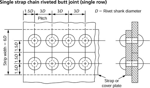
Note: This joint may also be double row riveted, chain or zigzag. The strap width = 12D when double riveted (pitch between rows = 3D).
Double strap chain riveted butt joint (double row)
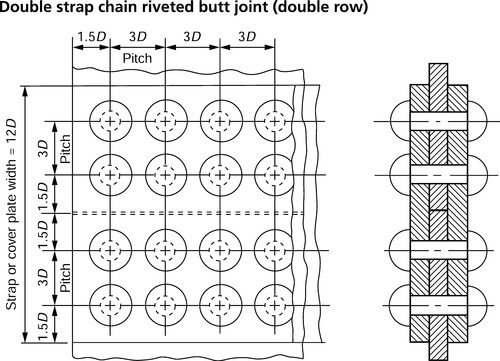
Note: This joint may also be double row zigzag riveted (see Section°4.2.2) or it may be single riveted as above.
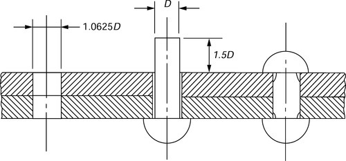
4.2.4 Proportions for hole diameter and rivet length
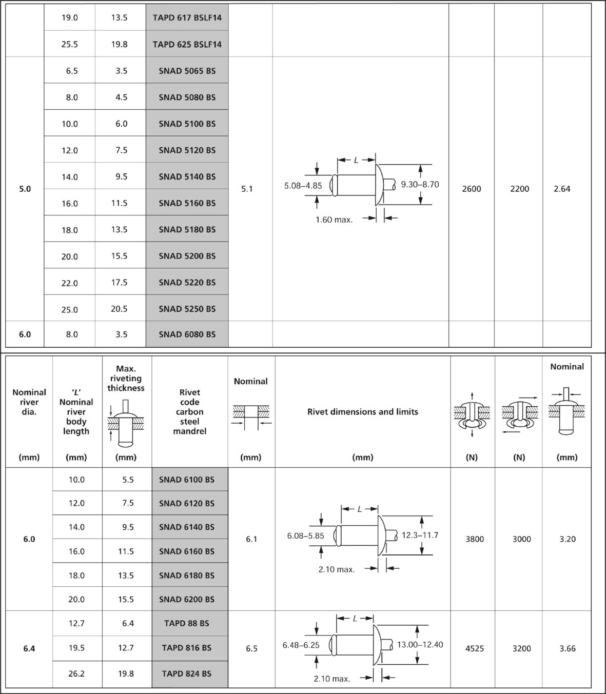
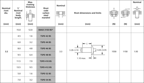
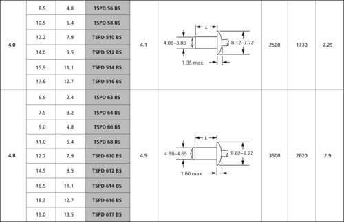
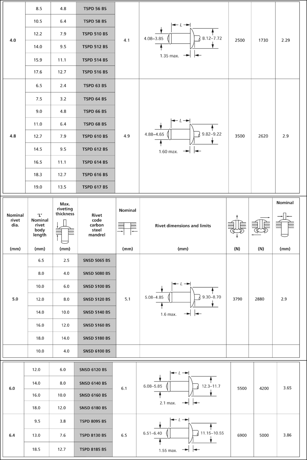
4.2.5 Cold forged snap head rivets

| Nominal shank diametera d | Tolerance on diameter d | Nominal head diameter D | Tolerance on diameter D | Nominal head depth K | Tolerance on head depth K | Tolerance on length L |
| 1 | 1.8 | 0.6 | + 0.2 | |||
| 1.2 | 2.1 | ± 0.2 | 0.7 | –0.0 | ||
| 1.6 | ± 0.07 | 2.8 | 1.0 | |||
| 2.0 | 3.5 | ± 0.24 | 1.2 | + 0.24 | ||
| 2.5 | 4.4 | 1.5 | –0.0 | |||
| 3.0 | 5.3 | 1.8 | + 0.5 | |||
| (3.5) | 6.1 | ± 0.29 | 2.1 | + 0.29 | ||
| 4 | ± 0.09 | 7.0 | 2.4 | –0.0 | ||
| 5 | 8.8 | 3.0 | ||||
| 6 | 10.5 | 3.6 | ||||
| + 0.35 | ||||||
| ± 0.35 | –0.0 | |||||
| (7) | 12.3 | 4.2 | + 0.8 | |||
| 8 | ± 0.11 | 14.0 | 4.8 | –0.0 | ||
| 10 | 18.0 | 6.0 | ||||
| 12 | 21.0 | ± 0.42 | 7.2 | + 0.42 | + 1.0 | |
| (14) | ± 0.14 | 25.0 | 8.4 | –0.0 | –0.0 | |
| 16 | 28.0 | 9.6 |

aRivet sizes shown in brackets are non-preferred.
For further information see BS 4620: 1970
4.2.6 Hot forged snap head rivets

| Nominal shank diametera d | Tolerance on diameter d | Nominal head diameter D | Tolerance on diameter D | Nominal head depth K | Tolerance on head depth K | Tolerance on length L |
| (14) | 22 | 9 | + 1.0 | |||
| 16 | ± 0.43 | 25 | ± 1.25 | 10 | + 1.00 | –0.0 |
| 18 | 28 | 11.5 | –0.0 | |||
| 20 | 32 | 13 | + 1.5 | + 1.6 | ||
| (22) | ± 0.52 | 36 | + 1.8 | 14 | –0.0 | –0.0 |
| 24 | 40 | 16 | ||||
| (27) | 43 | 17 | + 2.0 | |||
| 30 | 48 | ± 2.5 | 19 | –0.0 | ||
| (33) | ± 0.62 | 53 | 21 | + 3.0 | ||
| –0.0 | ||||||
| 36 | 58 | ± 3.0 | 23 | + 2.5 | ||
| 39 | 62 | 25 | –0.0 |
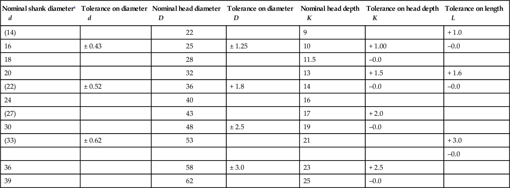
For further information see BS 4620: 1970.
a Rivet sizes shown in brackets are non-preferred.
4.2.7 Tentative range of nominal lengths associated with shank diameters
| Nominal shank diametera d | Nominal length* L | |||||||||||||||||||||
| 3 | 4 | 5 | 6 | 8 | 10 | 12 | 14 | 16 | (18) | 20 | (22) | 25 | (28) | 30 | (32) | 35 | (38) | 40 | 45 | 50 | 55 | |
| 1.0 | × | × | × | × | × | × | × | × | × | × | ||||||||||||
| 1.2 | × | × | × | × | × | × | × | × | × | × | ||||||||||||
| 1.6 | × | × | × | × | × | × | × | × | × | × | × | × | ||||||||||
| 2.0 | × | × | × | × | × | × | × | × | × | × | × | × | ||||||||||
| 2.5 | × | × | × | × | × | × | × | × | × | × | × | × | ||||||||||
| 3.0 | × | × | × | × | × | × | × | × | × | × | × | × | ||||||||||
| (3.5) | ||||||||||||||||||||||
| 4.0 | × | × | × | × | × | × | × | × | × | |||||||||||||
| 5.0 | × | × | × | × | × | × | × | × | × | × | × | × | × | × | ||||||||
| 6.0 | × | × | × | × | × | × | × | × | × | × | × | × | × | × | × | |||||||

aSizes and lengths shown in brackets are non-preferred and should be avoided if possible. The inclusion of dimensional data is not intended to imply that all the products described are stock production sizes. The purchaser should consult the manufacturer concerning lists of stock production sizes.
For the full range of head types and sizes up to and including 39 mm diameter by 160 mm shank length see BS 4620: 1970
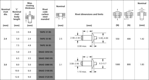
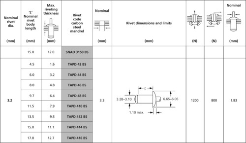
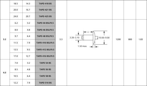
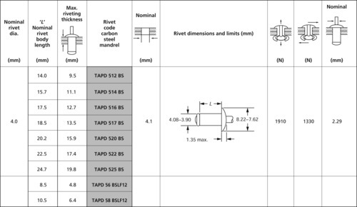
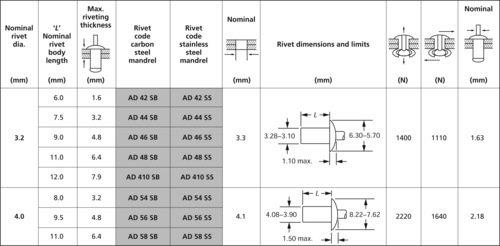
4.2.8 POP® rivets
POP® or blind riveting is a technique which enables a mechanical fastening to be made when access is limited to only one side of the parts to be assembled, although reliability, predictability, reduction of assembly costs and simplicity in operation, mean that blind rivets are also widely used where access is available to both sides of an assembly. POP® and other brands of blind riveting systems have two elements, the blind rivet and the chosen setting tool.
The blind rivet is a two-part mechanical fastener. It comprises of a headed tubular body mounted on a mandrel which has self-contained features that create (when pulled into the body during setting) both an upset of the blind end and an expansion of the tubular body, thus joining together the component parts of the assembly. The setting tool basically comprises an anvil which supports the head of the rivet and jaws which grip and pull the mandrel to cause it to set the rivet before the mandrel breaks at a predetermined load.
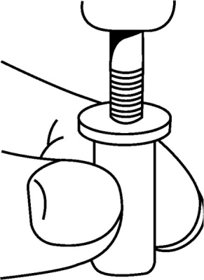
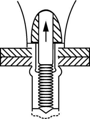
Many different styles of blind rivet are available but the most widely used is the Open End Rivet Body type defined in BS EN ISO 14588: 2000 as: 'A blind rivet having a body hollow throughout its length and able to use an standard mandrel'. The principle of blind riveting using open style rivets is shown in the following figure.
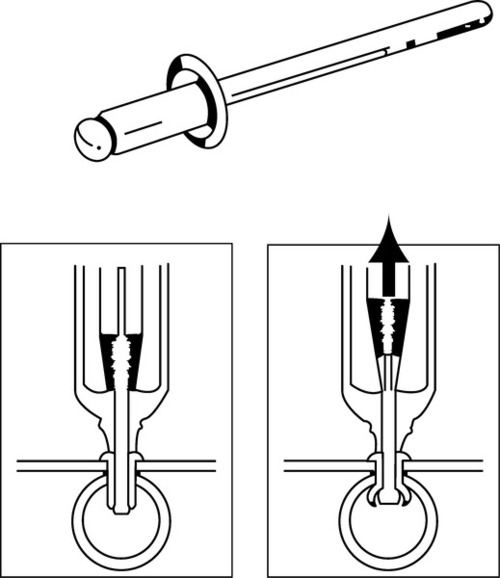
With the mandrel held in the setting tool, the rivet body is inserted into the pre-punched or pre-drilled component. Operation of the setting tool pulls the mandrel head into the rivet body causing it to expand on the blind side of the assembly, whilst drawing the components together and eliminating any gaps between them as it does so. At a predetermined point, when the blind side head is fully formed, continued operation of the setting tool causes the mandrel to break, the spent portion of the mandrel is pulled clear and the installation of the rivet is complete
The Closed End Rivet Body type is defined in BS EN ISO 14588: 2000 as: 'A blind rivet body which is closed and remains closed after setting'. This type is also commonly known as 'sealed'. The closed end rivet prevents ingress of vapour or moisture through the bore of the installed rivet and also ensures mandrel head retention, particularly important in electrical equipment, for example.
POP® blind rivets are available in a variety of materials, body styles and head forms to provide fastening options for a broad spectrum of assembly and environmental requirements from brittle and fragile materials such as acrylic plastics through to stainless steel. A summary is shown in Section 4.2.9. This figure and the following tables are taken from the publications of Emhart Teknologies (Tucker Fasteners Ltd.) from whom further information can be obtained. This company's address is listed in Appendix 3.
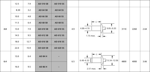
4.2.9 POP® range guide


Head style
The low-profile domed head is suitable for most applications but, where soft or brittle materials are fastened to a rigid backing, the large flat head variety should be considered. The 120° countersunk head style should be used wherever a flush surface is required.
Mandrel types
POP® open type rivets are normally supplied with 'Break stem' mandrels (code BS) designed to retain the mandrel head when the rivet is set. 'Break head' (code BH) mandrels, designed to eject the mandrel head from the rivet body, can be supplied for most open rivets and are particularly useful in the pre-assembly of electrical circuit boards.
Finish
• Rivet body standard finishes: Steel and nickel-copper rivet bodies are normally supplied zinc plated.
• Paint and other finishes: Rivets with differing surface finishes and paint colours can be provided on request. Aluminium alloy rivets are available anodized and dyed, matt or gloss for aesthetic and environmental reasons.
4.2.10 Good fastening practice
Blind riveting is a highly reliable and proven method of fixing material together permanently. To achieve a superior fastening, the following principles should be considered.
Workpiece materials
When materials of different thickness or strengths are being joined, the stronger material - if possible - should be on the blind side. For example, if plastic and metal are to be joined, the plastic sheet should be beneath the rivet head and the metal component should be on the blind side.
Hole size and preparation
Achieving a good joint depends on good hole preparation, preferably punched and, if necessary, de-burred to the sizes recommended in the POP® blind rivet data tables.
Rivet diameter
As a guide for load-bearing joints, the rivet diameter should be at least equal to the thickness of the thickest sheet and not more than three times the thickness of the sheet immediately under the rivet head. Refer to data tables for rivet strength characteristics.
Edge distance
Rivet holes should be drilled or punched at least two diameters away from an edge - but no more than 24 diameters from that edge.
Rivet pitch
As a guide to the distance between the rivets in load-carrying joint situations, this distance should never exceed three rivet diameters. In butt construction it is advisable to include a reinforcing cover strip, fastening it to the underlying sheet by staggered rivets.
Rivet material
Choosing rivets of the correct material normally depends on the strength needed in the riveted joint. When this leads to rivets of material different to the sheets being joined it is important to be aware that electrolytic action may cause corrosion. (See Section°4.2.12.)
Setting and safety
The type of setting tool is usually selected to suit the production environment. The tool must be cleared of spent materials before setting the next rivet and, in the case of power operated tools, must not be operated without the mandrel deflector or mandrel collection system being in position. Safety glasses or goggles should always be worn.
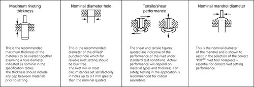
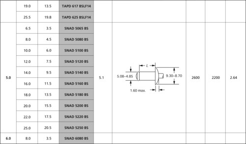
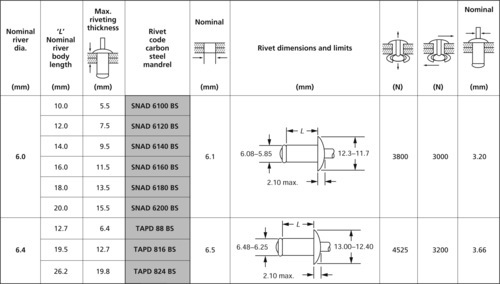
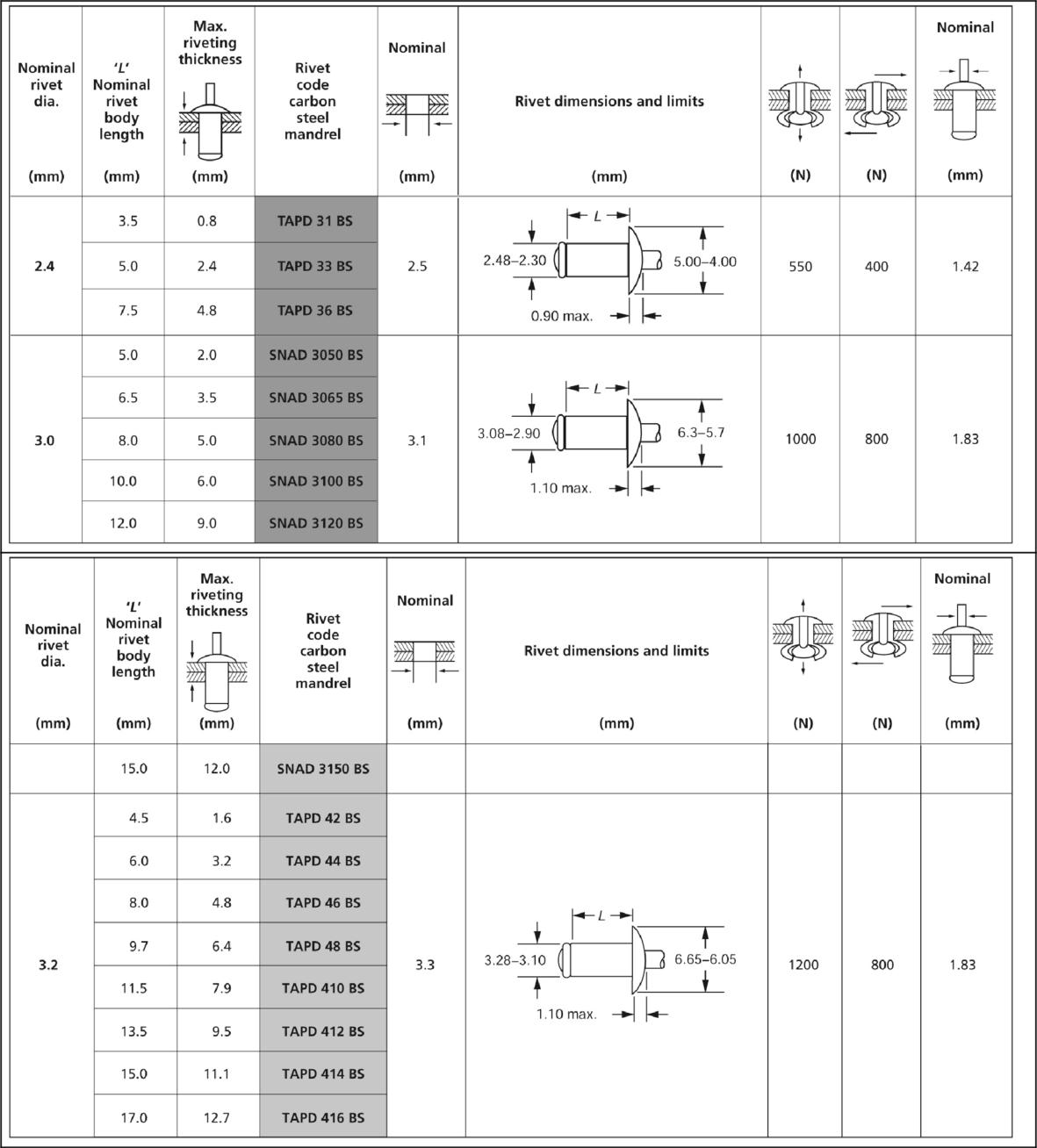
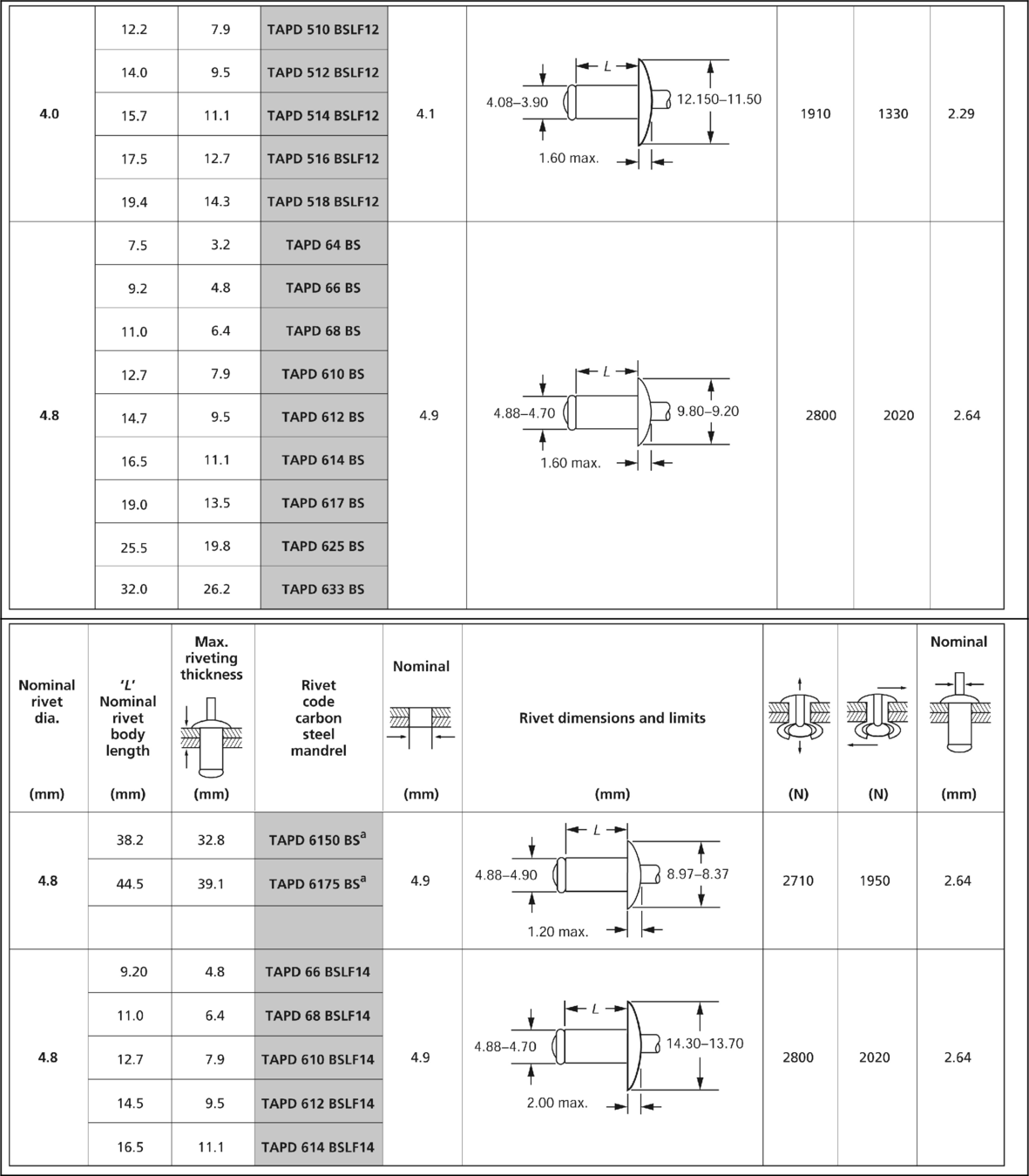
4.2.11 Selection of POP® (or blind) rivets
Joint strength
First assess the tensile strength and the shear-load strength required by the joint, both of which can be achieved by the correct number and spacing of fastenings, and by choosing a rivet with a body of the correct material and diameter. The strength columns on the data pages enable a rivet of the correct strength to be chosen.
Joint thickness
The next stage is to work out the combined thickness of the materials to be joined, remembering to allow for any air gaps or intermediate layers such as sealants. Then identify the selected rivet in the size with the necessary grip by consulting the data page. It is important to do this because a rivet with the incorrect grip range cannot satisfactorily grip the back of the workpiece or assembly.
Corrosion acceleration (nature of materials)
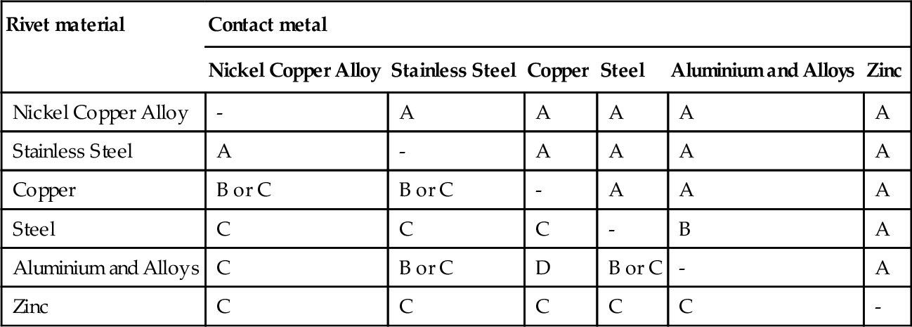
Finally, follow the general rule that the rivet chosen should have the same physical and mechanical properties as the workpiece. A marked difference in properties may cause joint failure through metal fatigue or galvanic corrosion. Corrosion is accelerated by certain combinations of materials and environments. Generally, avoid contact between dissimilar metals. The significance of the letters A, B, C and D in the following chart is as follows:
A The corrosion of the metal considered is not accelerated by the contact metal.
B The corrosion of the metal being considered may be slightly accelerated by the contact metal.
C The corrosion of the metal considered may be markedly accelerated by the contact metal.
D When moisture is present, this combination of metal considered and contact metals is inadvisable, even under mild conditions, without adequate protective measures.
Where two symbols are given (for instance B or C) the acceleration is likely to change with changes in the environmental conditions or the condition of the metal.
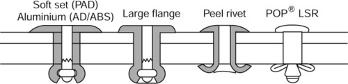
4.2.12 Design guidelines
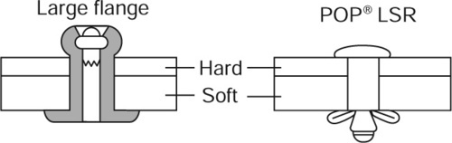
Soft materials to hard
A large flange rivet can be used with the flange on the side of the soft material. Alternatively, POP® LSR type rivets spreads the clamping loads over a wide area so as to avoid damage to soft materials.
Plastics and brittle materials
For fragile plastics and brittle materials, POP® riveting offers a variety of application solutions. Soft-set/All Aluminium rivets offer low setting loads, whereas both the 'Peel' and 'LSR' ranges affordenhanced support to the materialsbeing joined. For stronger plastics,standard POP® rivets – open or closed end products – may be used.
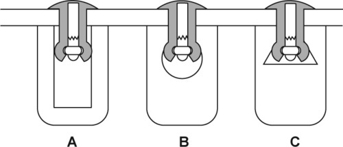
Channel section material
An extended nosepiece can be used to reach to the bottom of a narrow channel section (A) (see figure below). A longer mandrel rivet should be used and the maximum nosepiece diameter should be equal to that of the rivet flange. Alternatively, the rivet can be set from the other side (B) or the channel widened to accept a standard rivet and setting tool (C).

Thick/thin sheet
When materials of different thickness are to be fastened, it is best to locate the thicker plate at the fastened side (A) (see figure below). When the hole diameter in the thinner plate is large, a large flange rivet should be used (B). When the thinner plate is located at the fastened side, either use a backing washer (C) or ensure that the diameter of the hole in the thicker plate is smaller than the one in the thinner plate (D).

Blind holes and slots
The setting of a POP® or blind rivet against the side of a blind hole, or into and against a milled slot, intersecting hole or internal cavity, is possible because of the expansion of the rivet body on installation.
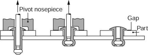
Pivot fastening
Use of a special nosepiece will provide a small gap between the rivet flange and the assembly, so providing for pivot action.
Hole diameters
Whilst standard hole diameters are the rivet body diameter plus 0.1 mm, component hole sizes may not always be this accurate, for example in pre-punched components. In cases when the hole on the fastened (blind) side is larger, POP® MGR rivets should be selected because of its superior hole filling characteristics. POP® LSR and POP® Peel rivets are also possible alternative solutions in these circumstances, especially when working with friable or fragile materials. Alternatively, when then larger hole is on the flange side, a large flange rivet should be chosen.
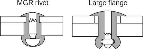
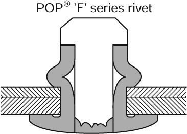
When, however, good hole filling and retained mandrels are used to give high shear and vibration resistance POP® 'F' series rivets should be specified. Section°4.2.13.)
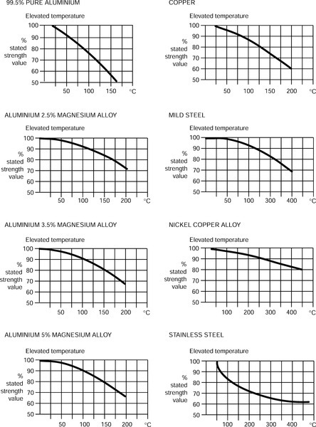
Elevated temperature performance
Elevated temperature strengths will vary from the figures quoted in the data tables. The following curves are offered for guidance.
4.2.13 POP® 'F' series
'F' Series: Domed head
Carbon steel (AISI 1006) mandrel: carbon steel


'F' Series: Domed head
Aluminium 3.5% Magnesium alloy (5052) mandrel: carbon steel
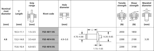

Note: Shear and tensile strengths are typical values. Joint strengths will be dependent upon the following application criteria:
1. Hole size, 2. Materials to be fastened, 3. Application material thicknesses
It is recommended users conduct their own test(s) to determine suitability for their application(s)
The following symbols are used in the tables in Sections 4.2.14-4.2.16.

4.2.14 Open type aluminium 3.5% magnesium alloy
Material composition: aluminium 3.5% magnesium alloy; mandrel: carbon steel


4.2.15 Open type carbon steel
Material composition: carbon steel; mandrel: carbon steel


4.2.16 Closed end type aluminium 5% magnesium alloy
Material composition: aluminium 5% magnesium alloy; mandrel: carbon steel or stainless steel

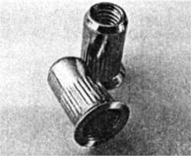
4.2.17 Blind rivet nuts
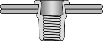
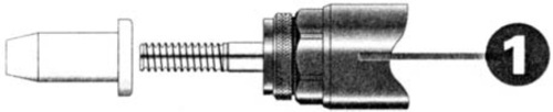
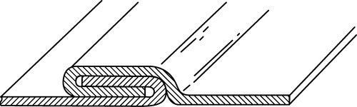
Blind rivet nuts are especially designed to offer a means of providing a stronger threaded joint in sheet and other materials and, like blind rivets, only require access to one side of the workpiece for installation. They are not only a form of captive nut but, unlike some other types, they also allow components to be riveted together as well providing a screw thread anchorage. The principle of their use is shown below.
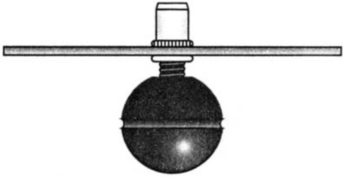
The POP® blind rivet nut is screwed onto the threaded mandrel of the setting tool and is then inserted into the drilled or punched hole.
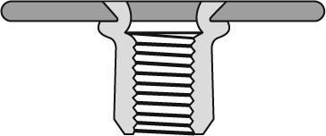
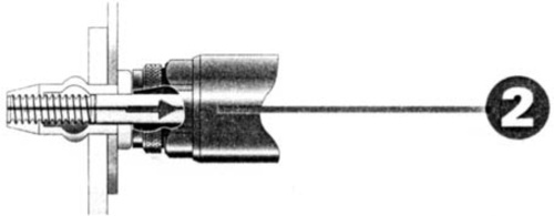
The tool is operated, retracting the mandrel. The unthreaded part of the nut expands on the blind side of the workpiece to form a collar and applies a powerful clenching force that rivets the components firmly together.
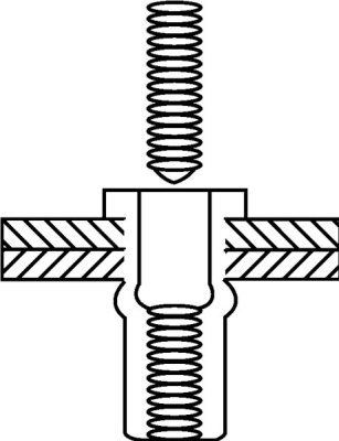
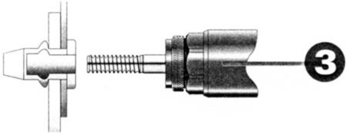
With the POP® nut firmly in position the tool mandrel is simply unscrewed from the nut. The threaded portion is now ready to act as a secure anchorage point.
Blind rivet nuts are generally available in thread sizes M3 to M12 in numerous combinations of head style, body form and material. Three head styles are available, flat head, 90° countersunk and, for thin gauge materials, a small flange which provides a near flush appearance without the need for countersinking.
Standard bodies are round with open or closed ends. The closed end prevents the ingress of moisture or vapour through the bore of the nut. Where a higher torque resistance is required, body forms may be fully or partially hexagonal (set in a hexagonal hole), or splined (set in a round hole)
4.2.18 POP® Nut Threaded Inserts: application
POP® Nut Threaded Inserts provide a simple and effective way to join materials with the benefit of an internal thread, in a variety of applications.
POP® Nut Threaded Inserts are the perfect solution for providing high-quality, load-bearing threads in various materials where alternative methods cannot maintain torque and pull out loads. POP® Nut Threaded Inserts are suitable for single sheets down to 0.5 mm.

POP® Nut Threaded Inserts enable components, which are assembled later in the production cycle, to be adjusted.
POP® Nut Threaded Inserts are ideally suited to applications where access is only available from one side of the workpiece.
4.2.19 POP® Nut Threaded Inserts: installation
POP® Nut Threaded Inserts are easily installed from one side of the workpiece without damaging surrounding surfaces of previously finished or delicate components and are suitable for use with all materials in today’s manufacturing environment:
• Available in a variety of materials
• Wide range of styles
• Complete range of Hand and Power setting tools
• Bulk and small pack available.
Install/screw the POP® Nut Threaded Insert to the tool’s threaded mandrel.
Operating the tool then retracts the mandrel. The unthreaded part of the nut then compresses to form a collar on the blind side of the workpiece, applying a powerful clenching force that firmly joins the components together.
With the POP® Nut Threaded Insert firmly in position, the tool mandrel is simply demounted/unscrewed from the insert.
The threaded part of the insert then acts as a secure anchorage point for subsequent assembly work.
4.2.20 POP® Nut: Steel
Flat head open end (with knurls)
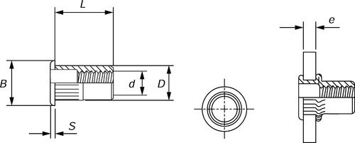

| Thread d | Description | Length (mm)L | Grip (mm) e | Hole dia. (mm) | Barrel dia. (mm) D | Flange dia. (mm) B | Flange thickness (mm) S | Bulk box quantity | Small pack quantity |
| M4 | PSFON430 | 10.0 | 0.3-3.0 | 6.0 | 5.9 | 9.0 | 1.0 | 10 000 | 500 |
| PSFON440 | 11.5 | 3.1-4.0 | 10 000 | 500 | |||||
| M5 | PSFON530 | 12.5 | 0.3-3.0 | 7.0 | 6.9 | 10.0 | 1.0 | 8000 | 500 |
| PSFON540 | 15.0 | 3.1-4.0 | 8000 | 500 | |||||
| M6 | PSFON630 | 14.5 | 0.5-3.0 | 9.0 | 8.9 | 12.0 | 1.5 | 4000 | 500 |
| PSFON645 | 16.0 | 3.1-4.5 | 4000 | 500 | |||||
| M8 | PSFON830 | 16.0 | 0.5-3.0 | 11.0 | 10.9 | 15.0 | 1.5 | 5000 | 250 |
| PSFON855 | 18.5 | 3.1-5.5 | 2000 | 250 | |||||
| M10 | PSFON1030 | 17.0 | 0.5-3.0 | 12.0 | 11.9 | 16.0 | 2.0 | 1500 | 200 |
| PSFON1060 | 22.0 | 3.0-6.0 | 1500 | 200 | |||||
| M12 | PSFON1240 | 23.0 | 1.0-4.0 | 16.0 | 15.9 | 22.0 | 2.0 | 1500 | 200 |
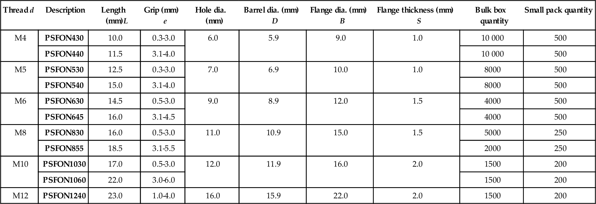
Flat head closed end (with knurls)
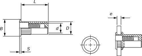

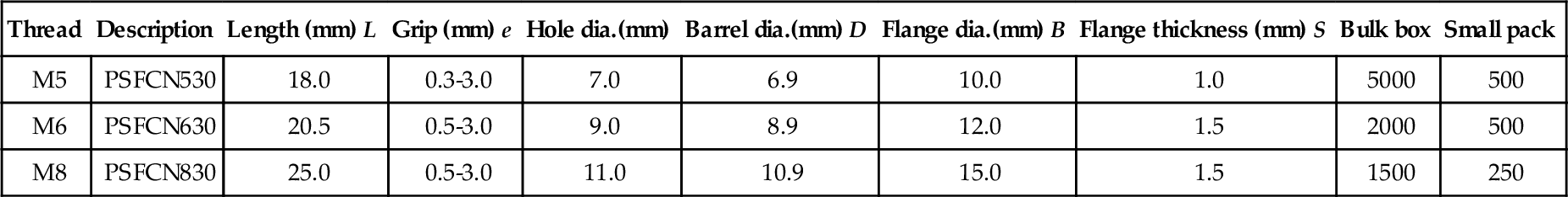
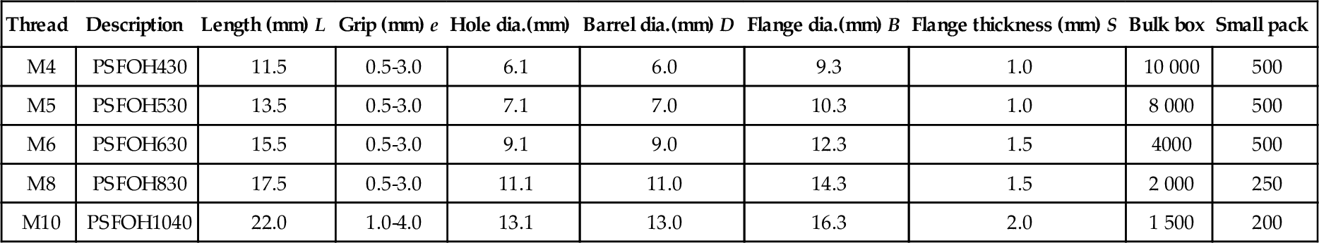
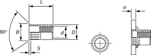
Flat head open end hexagonal


| Thread | Description | Length (mm) L | Grip (mm) e | Hole dia.(mm) | Barrel dia.(mm) D | Flange dia.(mm) B | Flange thickness (mm) S | Bulk box | Small pack |
| M4 | PSFOH430 | 11.5 | 0.5-3.0 | 6.1 | 6.0 | 9.3 | 1.0 | 10 000 | 500 |
| M5 | PSFOH530 | 13.5 | 0.5-3.0 | 7.1 | 7.0 | 10.3 | 1.0 | 8 000 | 500 |
| M6 | PSFOH630 | 15.5 | 0.5-3.0 | 9.1 | 9.0 | 12.3 | 1.5 | 4000 | 500 |
| M8 | PSFOH830 | 17.5 | 0.5-3.0 | 11.1 | 11.0 | 14.3 | 1.5 | 2 000 | 250 |
| M10 | PSFOH1040 | 22.0 | 1.0-4.0 | 13.1 | 13.0 | 16.3 | 2.0 | 1 500 | 200 |
Countersunk head open end (with knurls)
| Thread | Description | Length (mm) L | Grip (mm) e | Hole dia.(mm) | Barrel dia.(mm) D | Flange dia.(mm) B | Flange thickness (mm) S | Bulk box | Small pack |
| M4 | PSKON435 | 11.5 | 2.0-3.5 | 6.0 | 5.9 | 9.0 | 1.5 | 10 000 | 500 |
| M5 | PSKON540 | 13.5 | 2.0-4.0 | 7.0 | 6.9 | 10.0 | 1.5 | 8 000 | 500 |
| M6 | PSKON645 | 16.0 | 2.0-4.5 | 9.0 | 8.9 | 12.0 | 1.5 | 4000 | 500 |
| M8 | PSKON845 | 19.0 | 2.0-4.5 | 11.0 | 10.9 | 14.0 | 1.5 | 2 000 | 250 |
| M10 | PSKON1045 | 21.0 | 2.0-4.5 | 12.0 | 11.9 | 14.7 | 1.5 | 1 500 | 200 |

4.3 Self-secured joints
4.3.1 Self-secured joints
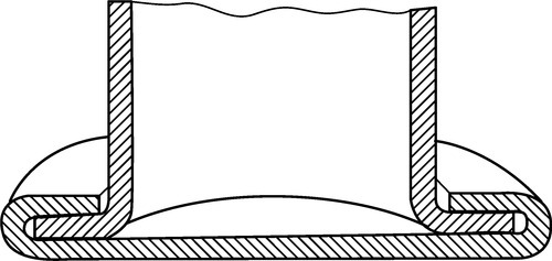
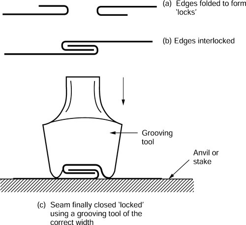
Grooved seam
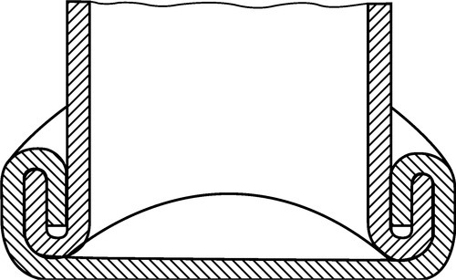
Double grooved seam

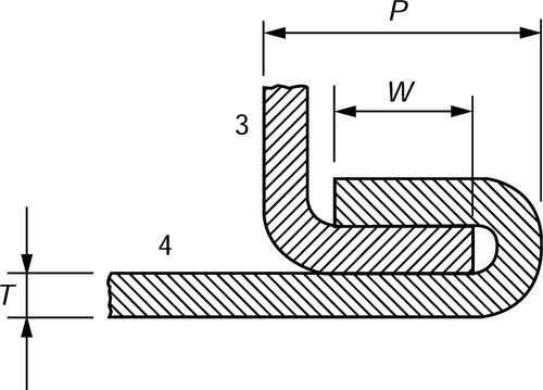
Paned down seam
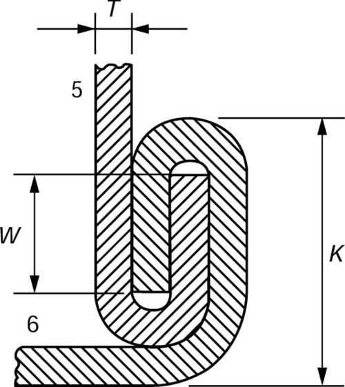
Knocked up seam
Making a grooved seam
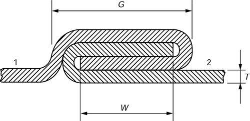
4.3.2 Allowances for self-secured joints
Grooved seam
Double grooved seam

Paned down seam
Knocked up seam
| Type of joint | Approximate allowance |
| Grooved seam | Total allowance = 3G - 4Tshared: (a) equally between limbs 1 and 2; or (b) two-thirds limb 1 and one-third limb 2 where joint centre position is critical. |
| Double grooved seam | Add W - T to the edge of each blank to be joined. Allowance for capping strip = 4W + 4T, where L = 2 W + 4T. |
| Paned down seam | Add W to the single edge 3. Add 2 W + T to the double edge 4. P = 2 W + 2T. |
| Knocked up joint | Add W to the single edge 5. Add 2 W + T to the double edge 6. K = 2W + 3T. |
4.4 Miscellaneous fasteners
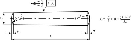
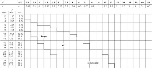
4.4.1 Taper pins, unhardened
Dimensions
Type A (ground pins): Surface finish Ra = 0.8μm
Type B (turned pins): Surface finish Ra = 3.2μm

Specifications and reference International Standards
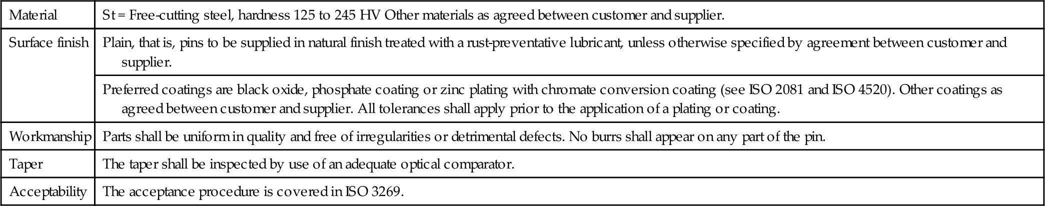
| Material | St = Free-cutting steel, hardness 125 to 245 HV Other materials as agreed between customer and supplier. |
| Surface finish | Plain, that is, pins to be supplied in natural finish treated with a rust-preventative lubricant, unless otherwise specified by agreement between customer and supplier. |
| Preferred coatings are black oxide, phosphate coating or zinc plating with chromate conversion coating (see ISO 2081 and ISO 4520). Other coatings as agreed between customer and supplier. All tolerances shall apply prior to the application of a plating or coating. | |
| Workmanship | Parts shall be uniform in quality and free of irregularities or detrimental defects. No burrs shall appear on any part of the pin. |
| Taper | The taper shall be inspected by use of an adequate optical comparator. |
| Acceptability | The acceptance procedure is covered in ISO 3269. |
Designation
Example for the designation of an unhardened steel taper pin, type A, with nominal diameter d =6 mm and nominal lengthl = 30 mmml:
Taper pin ISO 2339-A-6 x 30-st
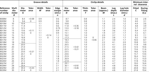
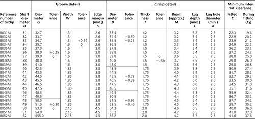
4.4.2 Circlips, external: metric series
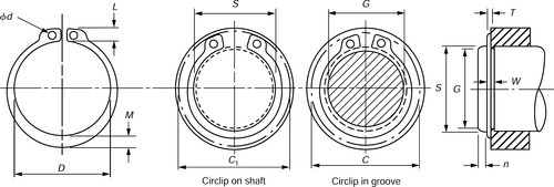

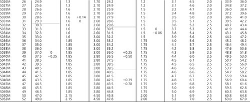
4.4.3 Circlips, internal: metric series

4.5 Adhesive bonding of metals
4.5.1 Anaerobic adhesives
These are high-strength adhesives widely used in the engineering industry. Anaerobic adhesives are single compound materials that remain inactive when in contact with oxygen. The adhesives require two conditions to be present simultaneously in order to cure. That is, the absence of oxygen and in the presence of metal parts. These adhesives are widely used for threadlocking, threadsealing, gasketing and retaining (or cylindrical part bonding) at room temperature where ideal conditions exist for the adhesive to cure as shown in Fig. 1.
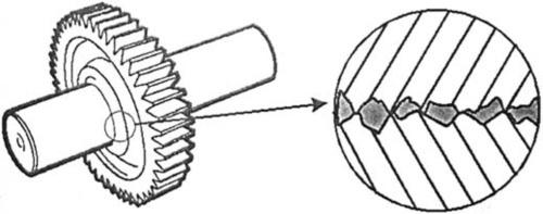
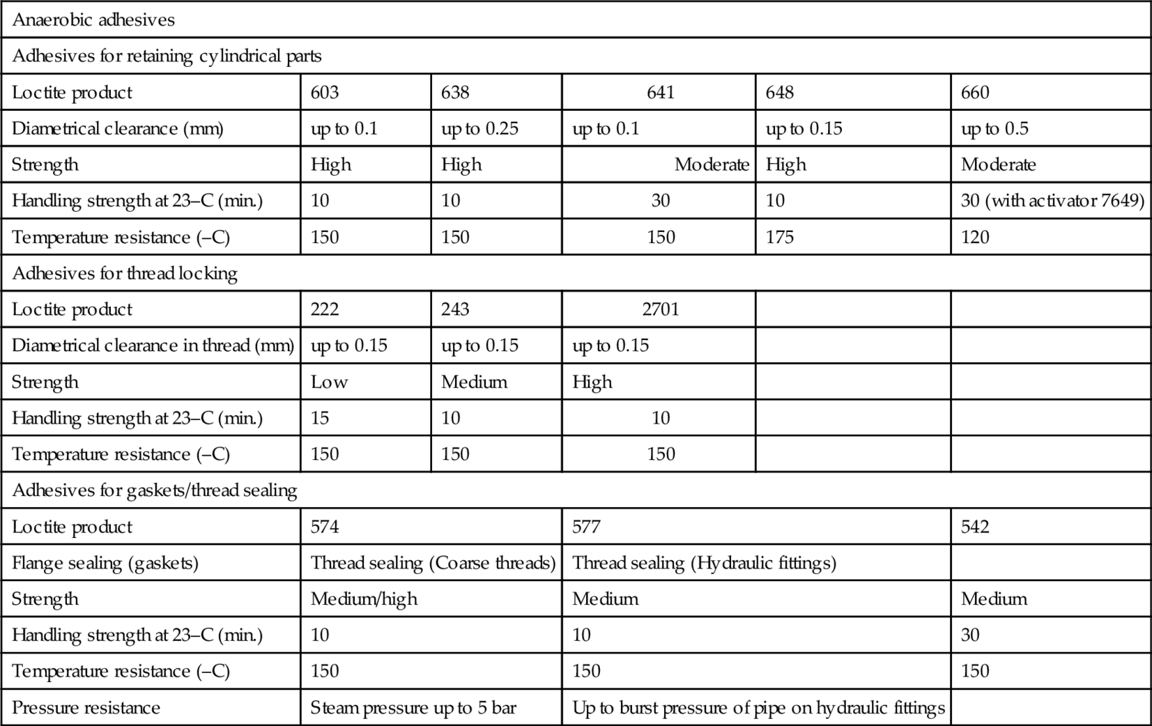
Copper, brass and plain carbon steel are 'active' as far as anaerobic adhesives are concerned and result in rapid curing at normal room temperatures. Stainless steel, aluminium and aluminium alloys, and plated products are 'passive' and require the use of an activator to ensure a full cure. As a liquid, the adhesive flows into the interstitial spaces between the male and female components of the joint where, devoid of atmospheric oxygen, it cures and becomes 'keyed' to the surface roughness. The curing process is also stimulated by contact between the adhesive and the metal surface that acts as a catalyst in the case of 'active'. Once cured to provide a tough thermoset plastic, the adhesive provides up to 60% of the torsional strength of the joint as shown in Fig. 2. To ensure a successful joint the mating surfaces must be mechanically and chemically clean before applying the adhesive and any activator necessary - normally to the male component for convenience. Handling strength is achieved within 10-20 min of the joint being achieved and full strength is attained in 4-24h depending on the gap between the mating components, the materials being joined and the temperature. The cured adhesives will resist temperatures up to 150°C and are resistant to most chemicals, although some higher temperature versions are available. Typical anaerobic adhesives from the Loctite product range and some applications are listed in Table 1.
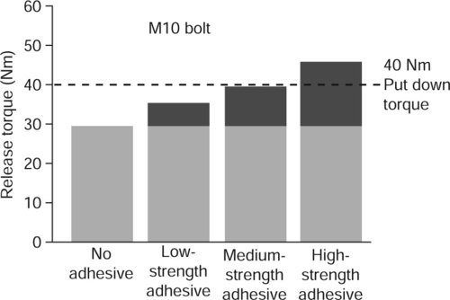
Table 1
Loctite product data
| Anaerobic adhesives | |||||
| Adhesives for retaining cylindrical parts | |||||
| Loctite product | 603 | 638 | 641 | 648 | 660 |
| Diametrical clearance (mm) | up to 0.1 | up to 0.25 | up to 0.1 | up to 0.15 | up to 0.5 |
| Strength | High | High | Moderate | High | Moderate |
| Handling strength at 23–C (min.) | 10 | 10 | 30 | 10 | 30 (with activator 7649) |
| Temperature resistance (–C) | 150 | 150 | 150 | 175 | 120 |
| Adhesives for thread locking | |||||
| Loctite product | 222 | 243 | 2701 | ||
| Diametrical clearance in thread (mm) | up to 0.15 | up to 0.15 | up to 0.15 | ||
| Strength | Low | Medium | High | ||
| Handling strength at 23–C (min.) | 15 | 10 | 10 | ||
| Temperature resistance (–C) | 150 | 150 | 150 | ||
| Adhesives for gaskets/thread sealing | |||||
| Loctite product | 574 | 577 | 542 | ||
| Flange sealing (gaskets) | Thread sealing (Coarse threads) | Thread sealing (Hydraulic fittings) | |||
| Strength | Medium/high | Medium | Medium | ||
| Handling strength at 23–C (min.) | 10 | 10 | 30 | ||
| Temperature resistance (–C) | 150 | 150 | 150 | ||
| Pressure resistance | Steam pressure up to 5 bar | Up to burst pressure of pipe on hydraulic fittings | |||
4.5.2 Adhesives cured by ultraviolet light
These are adhesives that are cured by the application of ultraviolet (UV) light. The cure times depend on the intensity and wavelength of the UV light which initiates polymerization.
Note: Suitable eye-protection should always be used when working with UV light.
Table 1
Loctite product data
| Anaerobic adhesives | |||||
| Adhesives for retaining cylindrical parts | |||||
| Loctite product | 603 | 638 | 641 | 648 | 660 |
| Diametrical clearance (mm) | up to 0.1 | up to 0.25 | up to 0.1 | up to 0.15 | up to 0.5 |
| Strength | High | High | Moderate | High | Moderate |
| Handling strength at 23 °C (min.) | 10 | 10 | 30 | 10 | 30 (with activator 7649) |
| Temperature resistance (°C) | 150 | 150 | 150 | 175 | 120 |
| Adhesives for thread locking | |||||
| Loctite product | 222 | 243 | 2701 | ||
| Diametrical clearance in thread (mm) | up to 0.15 | up to 0.15 | up to 0.15 | ||
| Strength | Low | Medium | High | ||
| Handling strength at 23 °C (min.) | 15 | 10 | 10 | ||
| Temperature resistance (°C) | 150 | 150 | 150 | ||
| Adhesives for gaskets/thread sealing | |||||
| Loctite product | 574 | 577 | 542 | ||
| Flange sealing (gaskets) | Thread sealing | Thread sealing | |||
| (Coarse threads) | (Hydraulic fittings) | ||||
| Strength | Medium/high | Medium | Medium | ||
| Handling strength at 23 °C (min.) | 10 | 10 | 30 | ||
| Temperature resistance (°C) | 150 | 150 | 150 | ||
| Pressure resistance | Steam pressure up to 5 bar | Up to burst pressure of pipe on hydraulic fittings | |||

Adhesives cured by UV light can be described as having high strength, high gap-filling capacity, very short curing times to handling strength, good to very good environmental resistance and good dispensing capacity with automatic systems as single-component adhesives.
The UV lamp is an essential part of the process and light sources can range from a simple bench-top open unit through to a fully automated conveyor system with several flood lights, incorporating special fixturing to hold the components in place during the curing cycle. UV light guides (or 'wand' systems) are often specified for small components as these units produce high-intensity light over a diameter of about 10 mm. These light guides ensure that the UV light is directed to the precise area for curing, thus minimizing glare and stray UV light. An example of a light guide is shown in the following figure.

In some applications, it is not always possible to ensure that the entire adhesive is exposed to the UV light and products are available which will cure after the UV cycle. There are several options for the secondary cure as follows.
Heat A secondary heat cure will ensure the full cure of many grades of UV adhesives. Cure temperatures are typically in the range 100-150°C
Anaerobic UV anaerobic grades are available for applications where a shadow cure is required. These anaerobic adhesives will cure through a depth of 0.2 mm due to contact with metal parts and the absence of oxygen.
Moisture UV silicone products will immobilize after UV cure and then continue to cure over 24h due to surrounding atmospheric moisture.
Surface moisture UV curing cyanoacrylates will cure through several millimetres with UV light but also cure due to surface moisture in shadowed areas.
One of the main reasons why UV adhesives are used is the benefit of 'cure on demand' (i.e. the ability to cure the product exactly when required once, and not until, the components are fully aligned).
4.5.3 Adhesives cured by anionic reaction (cyanoacrylates)
Single-component cyanoacrylate adhesives polymerize on contact with slightly alkaline surfaces. In general, ambient humidity in the air and on the bonding surface is sufficient to initiate curing to handing strength within a few seconds. The best results are achieved when the relative humidity value is 40-60% at the workplace at room temperature. Lower humidity leads to slower curing, higher humidity accelerates the curing but in extreme cases may impair the final strength of the bond.
After adhesive application, the parts must be assembled quickly since polymerization begins in only a few seconds. The open time is dependent on the relative humidity, the humidity of the bonding surfaces and the ambient temperature. Due to their very fast curing times, cyanoacrylate adhesives are particularly suitable for bonding small parts. UV curing grades are also available to improve the cure throughout the depth of the adhesive and to cure any excess adhesive. Cyanoacrylate adhesives should be applied only to one surface and the best bond is achieved if only enough adhesive is applied to fill the joint gap. Activators may be used to speed the curing process and to cure any excess adhesive. A further benefit of cyanoacrylates is that they can be used with primers to bond low-energy plastics such as polypropylene and polyethylene.
Features of cyanoacrylate adhesives are:
• very high shear and tensile strength;
• very fast curing speed (seconds rather than minutes);
• minimum adhesive consumption;
• almost all materials may be bonded;
• simple dispensing by good ageing resistance of single-component adhesives;
• simultaneous sealing effect.
4.5.4 Adhesives cured with activator systems (modified acrylics)
These adhesives cure at room temperature when used with activators which are applied separately to the bonding surfaces. These components of the adhesive system are not pre-mixed, so it is not necessary to be concerned about 'pot life'. The characteristic properties of modified acrylics are:
• very high shear and tensile strengths;
• good impact and peel resistance;
• wide useful temperature (-55°C to + 120°c);
• almost all materials can be bonded;
• large gap-filling capacity;
• good environmental resistance.
4.5.5 Adhesives cured by ambient moisture
These adhesives/sealants polymerize (in most cases) through a condensation effect that involves a reaction with ambient moisture.There are three types of adhesive in this category,namely:
• polyurethanes
• modified silanes.
Silicones
These materials vulcanize at room temperature by reacting with ambient moisture (RTV). The solid rubber silcone is characterized by the following properties:
• Excellent thermal resistance
• Flexible, tough, low modulus and high elongation
• Effective sealants for a variety of fluid types.
Polyurethanes
Polyurethanes are formed through a mechanism in which water reacts (in most cases) with a formulative additive containing isocyanate groups. These products are characterized by the following properties:
• Excellent toughness and flexibility
• Excellent gap filling (up to 5 mm)
• Paintable once cured
• Can be used with primers to improve adhesion.
Modified silanes
The modified silanes again cure due to reaction with atmospheric moisture and offer the following properties:
• Good adhesion to a wide range of substrates
• Isocyanate free
• Excellent toughness and flexibility.
It has only been possible to give a brief review of the main types of these specialized adhesives and the reader is referred to the technical literature published by the Henkel Loctite Adhesives Limited for detailed information on adhesive types and applications.
4.5.6 Epoxy adhesives
These are based on resins derived from epichlorhydrin and bisphenol-A. They are characterized by low shrinkage on polymerization and by good adhesion and high mechanical strength. These are usually 'two-pack' adhesives that are cured by mixing the adhesive with a catalyst (hardener) immediately prior to use. Curing commences as soon as the catalyst is added. However, in some instances the hardener is premixed by the adhesive manufacturer and is activated by heating to (typically) 150°C for 30 min. Typical epoxy adhesives are found in the Loctite® Hysol® range. The substrate selector guide is shown in Fig. 1.

Typical Hysol® epoxy adhesives are as follows:
1 General purpose epoxy adhesives:
• Multi-purpose adhesives for general bonding applications.
• Ultra-clear adhesives for transparent bond lines.
• Flexible adhesives for low stress bonding of plastics and dissimilar substrates.
2 Five-minute epoxy adhesives:
• Rapid cure for a fast fixture time.
• Ultra-clear adhesives for fast transparent bonding.
• Emergency repair of metal parts like pipes and tanks.
3 Toughened epoxy resins:
• Highest shear and peel strength.
• Excellent impact resistance.
• Adhesives for bonding high performance composites such as glass-reinforced plastics (GRP) and CFRP.
4 High-temperature epoxy resins:
• Resistance to high operating temperatures.
• UL94-V0 rating for fire retardant parts.
• High thermal conductivity.
5 Metal-filled epoxy resins:
• Rebuild and restore worn and damaged metal parts.
• Repair metal pipes and castings.
• Form moulds, tools, fixtures and models.
• Reduce sliding wear on moving parts.
Typical performance characteristics are shown in Fig. 2. The reader is referred to the comprehensive data published by Henkel Loctite Adhesives Limited who may be contacted at the address given in Appendix 3.

4.5.7 Redux process
A technique developed for bonding primary sheet metal aircraft components with a two component adhesive under closely controlled heat and pressure.
4.5.8 Bonded joints
It has already been stated that correct surface preparation is necessary for optimum bonding. Bond strength is determined to a great extent by the adhesion between the adhesive and the substrate. Therefore joint preparation should remove oil, grease, oxide films and dirt in order to ensure chemical and mechanical cleanliness. Mechanical surface treatment by grit-blasting or wire brushing ensures good adhesion.
In addition it is necessary to design the joint correctly. Adhesives are relatively strong in tension and shear but weak in cleavage and peel. Therefore the joint must be designed with this in mind and also provide an adequate surface area between the mating parts to ensure the required strength. That is, the joint must be designed with adhesive bonding in mind from the start and not just be an adaptation of an existing mechanical/welded joint. Fig. 1 below shows a number of correctly and incorrectly designed joints suitable for adhesive bonding.

The author is indebted to Mr Bob Goss, Senior Technology Specialist at Henkel Loctite Adhesives Limited for his assistance in compiling the above information on adhesive bonding
Bad practice
Distortion and failure of a simple lap joint
Good practice
Alternatives to the simple lap joint