
Not only does Visio make it easy to create connections in diagrams, it also makes it easy to modify those connections. Perhaps you need to add a missing step to a flowchart or adjust a series of steps to make a process more efficient. Maybe you need some of the connectors in a flowchart to be rerouted in a specific way. With Visio, you can insert shapes between shapes that are already connected and move shapes around while the connections stay intact, which makes modifying a flowchart painless.
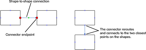
The method you use to connect shapes in a flowchart determines how the connectors are rerouted and how much control you have over where connectors are attached to shapes. In the previous exercise, you connected shapes with a shape-to-shape connection; that is, you connected shapes without specifying a point of connection. When you move shapes connected by a shape-to-shape connection, the connector reroutes and connects the shapes between the two closest points on the shapes. When you insert a shape between two shapes that are connected by a shape-to-shape connection, Visio connects all three shapes. For most types of flowcharts, shape-to-shape connections are sufficient because you don't usually need to control the exact point of connection on each shape. When you select the connector between two shapes with a shape-to-shape connection, the glued connector endpoints are large, light red, and have no begin point or end point symbols.
When you use the Connector tool to drag shapes onto the drawing page and connect them, Visio creates shape-to-shape connections by default. To draw a shape-to-shape connection yourself, you place the Connector tool over one of the shapes until you see a red border around the shape. Then you drag to the other shape, and when you see a red border around it, release the mouse button.
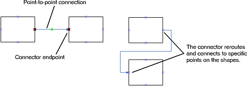
There might be times when you're working within design constraints that, for example, require all Yes connectors to flow from the right side of the shapes and all No connectors to flow downward in a flowchart. When you need total control over your shape connections, you can connect shapes with a point-to-point connection, which connects specific points on the shapes. When you move shapes connected by a point-to-point connection, the connector stays connected to those specific points, regardless of where you move the shapes. When you add a shape between two shapes already connected by a point-to-point connection, Visio connects all three shapes at specific connection points. When you select the connector between shapes connected by a point-to-point connection, the glued endpoints on the connector are small, dark red, and include begin and end point symbols.
To create a point-to-point connection, instead of positioning the Connector tool over the shape, you position it over a connection point —a specific point, represented by a blue x symbol.

When you place the Connector tool over a connection point on a shape, a small red box appears. Then you drag the connector to the small red box around the connection point on the shape to which you are connecting.
Tip
You can use both shape-to-shape connections and point-to-point connections in a flowchart. You can also create your own connection points. For information about creating connection points and the different types of connection points, type "connection points" in the "Type a question for help" box. Then read the "About connection points" and "Work with connection points" Help topics.
In this exercise, you move a flowchart shape to a new position and see how the connector moves with the shape. You also insert a flowchart shape between two shapes that are already connected. Then you move two shapes that are connected by a shape-to-shape connection and create a point-to-point connection between them using the Connector tool. Finally, you modify a connector segment and attach a connector endpoint to a different shape.
OPEN the ConnectModify file in the My DocumentsMicrosoft PressVisio 2003 SBSConnectingShapes folder.
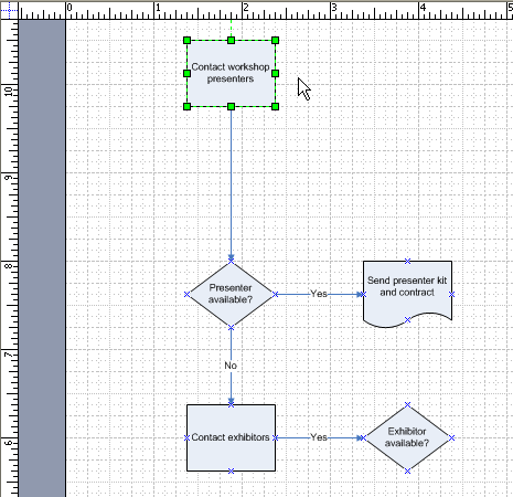
Drag the Contact workshop presenters shape up approximately one inch. The connector is resized but stays connected to the shape.
From the Basic Flowchart Shapes stencil, drag a Process shape onto the drawing page and position it on the connector between the Contact workshop presenters shape and the Presenter available? shape.
As you hold the Process shape over the connector, the pointer changes to a scissors icon, indicating that you can cut, or split, the existing connection and reconnect all three shapes in the series.
Release the mouse button.
Visio connects all three shapes in the series.
Important
Not all templates and connectors support connector-splitting behavior. To determine whether a template and connector support this behavior, drag a shape onto a connector between two shapes. If the connector is rerouted around the shape rather than attaching to it, the template, connector, or both don't support this behavior. To determine whether a particular connector supports splitting behavior, right-click the connector, point to Format on the shortcut menu, and then click Behavior to see the Connector splitting settings.
With the Process shape selected, type Send follow-up e-mail.
Visio zooms in so that you can easily read the text as you type.
Click the pasteboard to deselect the shape and zoom out again.
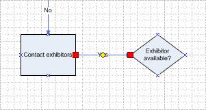
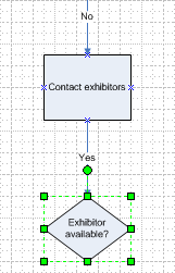
Select the connector between the Contact exhibitors shape and the Exhibitor available? shape.
The endpoints on the connector are large and light red, indicating that the shapes are connected with a shape-to-shape connection.
Drag the Exhibitor available? shape below the Contact exhibitors shape, and use the dynamic grid to align the two shapes.
The connector is rerouted and connects the shapes between the two closest points.
Select the rest of the connectors in the flowchart—one by one—and notice that all the shapes in the flowchart are connected with shape-to-shape connections.
From the Basic Flowchart Shapes stencil, drag a Document shape onto the drawing page. Use the dynamic grid to position it to the right of the Exhibitor available? shape and align it with the Send presenter kit and contract shape.
Click the pasteboard to deselect the shape.
On the Standard toolbar, click the Connector Tool button.
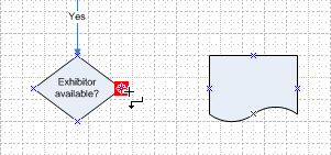
Position the pointer over the right connection point on the Exhibitor available? shape.
A small, dark-red box encloses the connection point, indicating that you can draw a connector starting from that connection point.
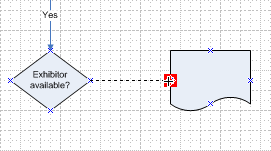
Drag to the left connection point on the Document shape.
A red box encloses the connection point on the Document shape.
Release the mouse button.
Visio draws the connector and connects the two shapes using a point-to-point connection. Notice the small, dark-red endpoints on the connector, which indicate a point-to-point connection.
With the connector selected, type Yes.
Visio zooms in so that you can see the text as you type.
On the Standard toolbar, click the Pointer Tool button.
Select the Document shape, and type Send informational kit.
Click the pasteboard to deselect the shape.
Drag the Send informational kit shape below the Exhibitor available? shape.
Visio reroutes the connector, but the shapes remain connected at the same connection points.
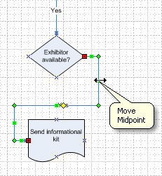
Select the connector between the Send informational kit shape and the Exhibitor available? shape.
Position the pointer over a midpoint on the right side of connector.
A ScreenTip appears.
Drag the midpoint a little to the right to move that segment of the connector.
Tip
Connectors have a shortcut menu just as other shapes do. You can use the commands on a connector's shortcut menu to access commands that are unique to connectors, such as the Right-Angle Connector, Straight Connector, and Curved Connector commands. Right-click a connector to display its shortcut menu.
Move the Send informational kit shape up, and position it to the right of the Send presenter kit and contract shape.
The connector stays attached to both connection points on the shapes.
Select the connector between the Send informational kit shape and the Exhibitor available? shape.
Place the pointer over the red connector endpoint on the Exhibitor available? shape.
Drag the endpoint to the right connection point on the Send presenter kit and contract shape.
Visio glues the endpoint to the connection point on the Send presenter kit and contract shape and creates a new point-to-point connection.
On the Standard toolbar, click Save to save your changes to the diagram.


CLOSE the ConnectModify file.