

Photo by Arnaud Frich.
Joined Panoramas
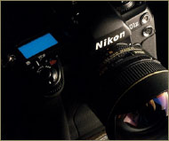
The method of joining is starting to revolutionize panoramic photography. It is no longer necessary to have one or more specialty cameras to make high-quality panoramic photos. A conventional (non-panoramic) camera, a computer, and a joined software program are all that is needed.
One of the main sticking points for taking panoramas has long been the need to own a specialty camera. These types of camera, studied in the preceding chapters, generally allow for only one kind of photo to be made, even if it often is of high quality and very original. But thanks to data processing, it is now possible to obtain the same quality with a conventional camera by joining several photographs. With certain high-performing software packages, one really can imitate a panoramic photo made with cameras like the Hasselblad XPan, the Noblex, or even the Roundshot. On a technical level, sometimes it is even possible surpass certain specialty cameras, even top-of-the-line ones, thanks to shifting possibilities available when making the exposure.
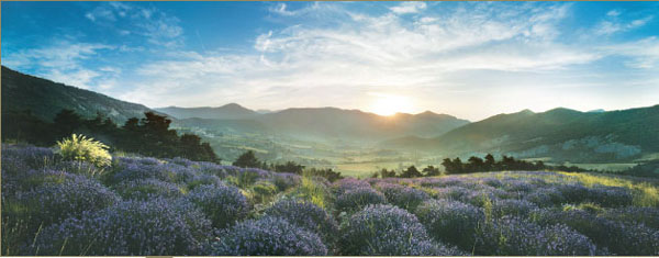
Photo by Bertrand Bodin.
If one uses a conventional camera – preferably digital – to make photographs that are intended to be joined, it is quite desirable to have that practical and special accessory, a panoramic viewfinder, in the camera bag. This will make the exposure of successive photos very easy and will allow one to photograph rather fleeting events as well. The preparations for taking pictures and the different steps in the joining method are presented in this chapter. The software and the joining itself will be discussed later, in the following chapter.
Making joined panoramas simply involves taking numerous photos that slightly overlap, and joining them afterward with a specialty software program. The kind of image and the resultant quality very much depends on the joining software package chosen. Among the better of these, there are three kinds of assemblage and, therefore, three different visual signatures:
1. The mode Quick Time Virtual Reality (QTVR) presents a normal (noncurved) visual signature. The photo opens up in a window with a nonpanoramic 4:3 ratio. Using the mouse, this image becomes interactive, and one can enter it and turn 360°.
2. The flat mode, also called rectilinear or orthoscopic, allows one to join images having the same signature as a photo taken with an XPan, a Linhof 617, and so forth. The maximum angle of view is therefore around 110°. Today, few software programs allow for this type of assemblage.
3. The more common tiled mode allows you to join images having the same visual signature as a photo made with a swing lens (Noblex, Widelux, etc.) or with a rotational camera (Roundshot, Eyescan, Spheron, etc.).
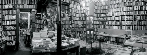
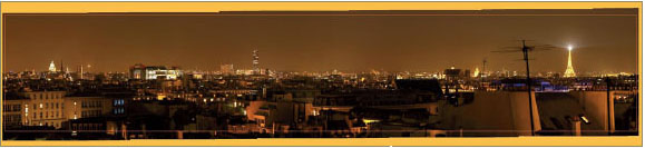
This series of images has been joined to form a veritable panoramic photograph where nothing allows you to say with certainty that it has been done this way.
Photo by Arnaud Frich.
If you use a digital camera with a large capacity sensor, you can join a printable panoramic image that is identical to one made from a specialty camera and conventional film. Therefore, this method is limited only by the imagination of the photographer who uses it
What follows is a résumé of various important steps in making a joined panoramic photograph.
1. Take care in choosing the point of view, the angle of view of both the camera and lens, and the focal length and placement of the critical focus desired. Preview the depth of field wanted. Placement of the critical focus most often will be set at the hyperfocal distance.
2. Once the tripod has been set up, level it along the axis of rotation, or else the photo will appear tilted.
3. Place the camera at the entrance pupil in order to verify that the lens does not tilt, unless the assemblage is done with Autopane Pro, ImageAssembler from Panavue, PT Gui, or with Stitcher. With these three software programs, tilting the camera while taking the picture is possible.
The entry pupil, often called the nodal point, is the ideal point of rotation for the camera during exposure.
4. Meter the light in terms of both quantity and quality: first, determine the overall exposure that all the photos will need to receive. Then, verify the difference in contrast from left to right or from interior to exterior. If possible, preview a slight correction of exposure between the images and, in certain cases, two sets of exposures for the interior and exterior. This must be done in the manual exposure mode since only this guarantees exposure regularity from one picture to the next. It is absolutely necessary to avoid having two consecutive photos with different levels of luminosity. It is equally important to choose a color temperature and avoid leaving the camera with the automatic white-balance mode turned on, as we will see a little later.
5. When taking the picture, make sure that the images superimpose by at least 20 percent and correct exposure if necessary (always in manual mode).
6. Retouch the photos after scanning them if traditional prints are used: verify that the light level, colors, and such are balanced between each shot and make any adjustments as needed. Some aesthetic retouching can also be done at this stage or at the end of the process. Finally, and this is perhaps the most important thing, correct the optical distortions that often occur with wide-angle zoom lenses and short focal lengths.
7. Join the images with a dedicated software program like Autopane Pro, ImageAssembler from Panavue, PT Gui, or with Stitcher.
8. Last-minute retouching: address these last corrections of lighting, dabbing, and so on, and determine the resolution with regard to the final result wanted (Web or print-out).
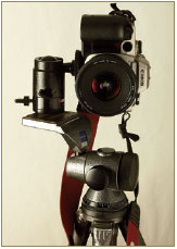
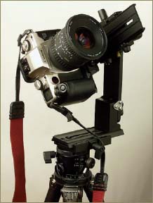
In the list of necessary equipment for a joined panoramic photo, one will obviously find a nonpanoramic, conventional camera. A digital camera would be preferable, but any traditional camera will do. The larger it is, the larger the sensor or film will be, and, thus, the better the end-result will be in terms of quality. In the preceding paragraph, I mentioned that it was important to place the camera at an ideal point of rotation called the entrance pupil of the lens. Manfrotto has made and commercialized a perfectly adapted accessory for this, the QTVR 303 head. But some photographers may prefer to make a custom-built panoramic tripod head instead.
The easiest way to avoid having to develop film in addition to scanning is to own a digital camera. The larger the negative or file, the better the final result, if one wants to make large prints. Some American photographers already understand this and therefore use 4 × 5 view-cameras in making panoramas. The manipulation of numerous film-planes makes taking the picture rather tedious, but the detail and tonality of the resulting panoramic photograph will be particularly beautiful. One thing is sure, the limiting factor is not the quality of the joining software, since these are quite adaptable and efficient.
Digital or traditional, large or small format, any conventional camera will work.
It is strongly recommended that the camera have the following:
• A manual exposure mode or compensating system of exposure
• An effective shade for the lens (this is nearly indispensable)
• A sufficiently large memory (digital camera)
• A white-balance that can be overridden (digital camera)
Apart from these, it would also be helpful to have the following:
• A swiveling screen (digital camera)
• Resolution equal to or greater than 2 Mb of pixels (digital camera)
• A wide-angle setting of at least 35 mm without needing additional components
• A spot meter
• An attachment that allows the viewfinder to be set at the axis of the lens
• A hot-shoe (to hold the level)
The choice of the lens and focal length is the photographer’s, with regard to the equipment being used. But one thing is sure, one should not hesitate from choosing or trying long focal lengths, very short wide-angle lenses, and so on. That’s the interesting thing in this method: extending the playing field. However, from now on shifting (PC) lenses are off-limits, except if the joining is done with PhotoShop or Panorama Tools (see Chapter Two).
The picture-taking method just described makes a tripod necessary, which makes the framing more deliberate and precise. However, if you tend to take candid pictures, don’t let the opportunity pass; shoot without a tripod.
With certain zoom lenses, the camera becomes displaced with regard to the rotational axis when the lens is set at the entrance pupil. Therefore, it is preferable to have a stable tripod in order to prevent vibration of the panoramic tripod head. As with other panoramic cameras, it will be advantageous to pick a tripod that can be set up both close to the ground and quite high, so as to vary the view a bit.
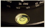
Although one can avoid placing the camera at the entrance pupil to gain a little time, it remains indispensable that the camera remain horizontal during rotation. A level is required therefore; otherwise, the joined images would give the impression of tilting to the left or right. Under these circumstances, it becomes necessary to reframe it, so that the area used will gradually shrink away in height. A simple level can do this, but a level like the one found on the base of a Manfrotto 303 head or on many other tripods is ideal. Certain levels with two perpendicular bubble housings can also be attached to the camera’s hot shoe.
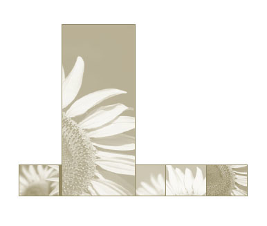
The usable image band is significantly reduced after cropping the joined image.
Photo by Arnaud Frich.
For anyone who wants to make a high-quality joined panoramic photograph, strongly recommend placing the camera at the entrance pupil of the lens during the entire rotation; the joining software can still repair many problems and make perfect connections. When using the software programs, the largest difficulty concerns a foreground subject interrupting the flow of the horizon. I can state from experience that the problem is greatly reduced when the foreground starts at a significant distance from the camera.
The most important technical question in joined panoramic photography involves the following. The entrance pupil (to be studied in detail later) always remains the same for a given camera and lens focal length, so finding it each time is not necessary. Once it has carefully been determined, the camera is placed on the panoramic tripod head at the predetermined spot for the focal length in question, which was noted previously.
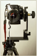
To place a camera at this ideal point of rotation, and in the vertical position (which gains the maximum in height), numerous equipment possibilities exist such as the Panosaurus head set; the most practical is undeniably the Manfrotto 303/303+/303SPH head.
Because of the notches on the ball-and-socket joint of the Manfrotto QTVR head, it is easy to return the camera to the same position or one or two pixels to one side. This turns out to be very useful when doubling the number of exposures in two typical scenarios: in order to reduce sensor interference, or, a more frequent scenario, to make a second series of images when photographing an interior opening onto an exterior. First, a series that is correctly exposed for the interior is made, followed by a second series for the exterior, while making sure to rotate the ball-and-socket joint so that it stops just one or two pixels short of the next image (this noticeably helps to reduce digital image noise). All that remains is to attach the images using retouching software like PhotoShop, and then join them in an adequate software program.
303 versus 303+
Model 303+ differs from model 303 in the micro-metrical adjustment of the two respective platforms. But ultimately, this seems little more than a gimmick. Both platforms are a bit longer, thus providing more room for adjustment, and something that is needed with the latest fast and bulky zoom lenses for 35 mm. Here, one must also bear in mind that the second model cannot be taken apart so as to be more easily stored in the camera bag. Also, although being longer, 303+ platforms are sometimes still not long enough. In this case, it is necessary to add a sliding plate (reference nos. 357 or 454) to the tripod mount of the camera.
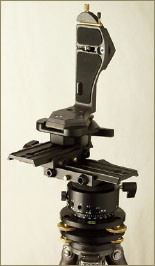
Manfrotto 303, 303+, and SPH Heads
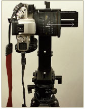
These well-designed panoramic tripod heads are made of different parts that serve our needs perfectly. And since autumn 2003, Manfrotto has sold a new panoramic tripod head, the 303 SPH. The latter is quite suited for making 360 × 360° photos for QTVR, but it is equally good for tilting the camera to take the picture (while always being set at the entrance pupil).
1. The stand (reference no. 338), having precise controls, allows one to put the final touches on leveling the tripod. Just remember, the head needs to rotate on the vertical axis, as we observed when discussing the level.
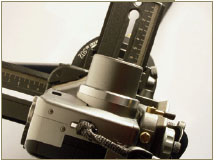
2. The panoramic ball-and-socket head (reference no. 300N) allows one to select the angle of rotation between each picture (10° to 90°) using a graduated and notched scale. Obviously, the angle depends on the focal length of the lens. This is more convenient than it may seem, since among the other graduated stands and ball-and-socket heads that I occasionally use, like those made by Novoflex or Gitzo, this is the only one that is notched.
To join two images correctly, the software programs require an overlap of around 20 percent. Therefore, all that is needed is to set the stop at the proper notch, which depends on the focal length and horizontal angle of view of the lens. Every time that one turns the panoramic tripod head, it will automatically stop at the next notch.
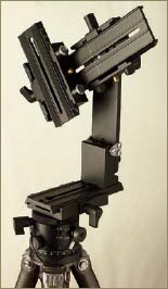
Panoramic tripod head. Manfrotto 302
Panoramic tripod head. 303 SPH
The panoramic ball-and-socket head is very helpful in normal use and even indispensable at times. On several occasions, I have needed to take 360° photos from places like snow-lined Parisian rooftops or the peaks of mountains, and I could not have turned the camera otherwise because it was set at the edge of a precipice. Not being able to watch things from the viewfinder, thus was enabled to control the angle of rotation during exposure.
Also, thanks to the notch on the ball-and-socket head, one can close the eyepiece of the viewfinder to ensure that there will not be any light-leaks; this is a real problem with cameras that have a fixed, semi-reflective mirror. (This has caused me to lose several photos due to a significant halo.)
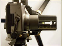
Other strong points with panoramic tripod heads are that they have two or three perpendicular ruler settings (two for the 303 and 303+ models, and three for the 303 SPH); these aid in setting the entrance pupil of the lens exactly above the rotational axis, no matter what camera, lens, and potential degree of tilt is being used. Panoramic tripod heads are more cumbersome than a custom-designed system, but very adaptable when switching to wide-angle or telephoto lenses. One final remark: a square helps to position the camera vertically, in order to obtain the maximum angle of view when using the 303 and 303+ models.
Custom-Built Mounts
As a less cumbersome and cheaper alternative to the QTVR Manfrotto panoramic tripod head, I had the simple idea to put two ball-and-socket joints together. This remains less functional, because it is more tiresome to level, and it is difficult to get it to work, but it occupies much less space in the camera bag and is lighter – the only added weight is that of the second ball-and-socket joint. Additionally, this alternative can accommodate a wide range of cameras, digital or otherwise.
Mounting a camera at the entrance pupil with two superimposed ball-and-socket joints. Although less practical than a real panoramic tripod head, this system is far less bulky.
One can also build a mount on the base of a metal square found in a hardware store, or on a sliding Manfrotto stand where the entrance pupil of the lens is located exactly above the rotational axis of the ball-and-socket joint. This produces a specially designed head that is not very cumbersome. The downside is that it is necessary to make a new head for each camera. Nevertheless, this solution remains clever and economic.
If one normally rests satisfied with the camera’s built-in light meter for overall light-meter readings, it nevertheless becomes necessary at times to measure contrast differences with further precision – notably interiors, sunny weather, and harsh lighting. To do this, a photographer will need to use either the spot meter in the camera, if it has one, or a hand-held spot meter, which offers more precision. A photographer who normally uses a hand-held light meter to take incident readings will also want to use a spot meter in these situations. After a reading is taken, the camera is adjusted, set in manual mode, relative to the shutter speed and aperture settings indicated by the light meter.
Although it is strongly recommended to make exposures in manual mode so that all the photos receive the same amount of light, certain software programs can balance minor light-level differences between consecutive pictures without too much problem – a little bit like the Noblex and its Panolux light meter. If the sun is to the right, especially when the field of view taken in exceeds 150°, subjects to the left will be found in the highlights, whereas those to the right will be in shadow. But through the use of slight exposure corrections while taking the picture, it is possible compensate for this by underexposing the areas in full sunlight and overexposing shadow areas. The only limit here is that one has to strictly avoid not adjusting the exposure by more than a third of a stop between consecutive images. In this way, one gains at least two stops for the entire joined panorama.
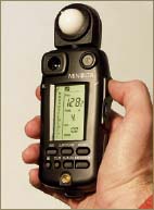
The Minolta VI flash meter has two measuring systems: an incident meter and a spot meter. Perhaps this is the absolute weapon for the panoramic photographer?
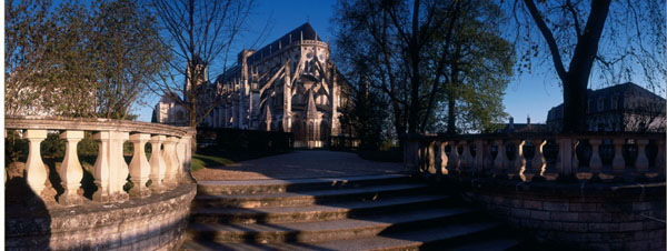
Photo by Arnaud Frich.
This equipment category is “accessory” in name only! Depending on the joining method chosen – and, thus, the kind of photograph made – the following accessories will prove to be indispensable and can help produce an image of a very high technical quality. However, since these accessories do not specifically pertain to panoramic photography, their use is more limited than in nonpanoramic photo, mainly because of the wide field being photographed.
Cable Release
If the entrance pupil of the camera is placed above the rotational axis of the ball-and-socket joint, it’s because to the burden of carrying a heavy and cumbersome tripod is worth it in order to obtain the best possible quality of assemblage. With such a qualitative approach, it will be quite common to use a cable release to avoid shaking or vibrating the camera. In certain situations, it is nearly indispensable (e.g., when the tripod is fully extended or during the long exposure times needed with nocturnal pictures). It takes the form of a flexible cable, or with the more modern cameras, a cordless infrared remote control.
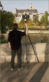
When the tripod is completely extended, a cable release is needed to avoid touching the camera.
Filters
There is no law against using filters when taking pictures that will eventually be joined – quite the contrary! As in conventional photography, as distinguished from panoramas, filters serve to reinforce the message or vision of the photographer. Whether he or she photographs with black-and-white or color film, or with a digital camera, the photographer selects from filters (made by different manufacturers) that can color correct (color film), increase color saturation, or improve contrast (notably with black-and-white). But before referring you to the imposing literature on the subject (see the bibliography booking Appendix A), first want to offer some advice concerning certain filters that often are used in joined panoramic photography:
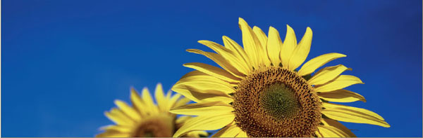
The photographer has chosen to use a polarizing filter to reinforce the contrast between the sunflower and the deep blue of the sky.
Photo by Benoît Ancelot
1. A graded, neutral density filter will certainly be very useful for landscape panoramic photographers. In many cases, this gradient and stopping down will be enough to avoid overexposing the sensor in the highlights (i.e., the sky). But if one seeks to obtain a less realistic, artistic effect, a denser filter will be needed.
2. A polarizing filter, very practical in normal photography, should be used with caution. It represents a special case because the field of view being photographed is often wider than 100°. Normally, this filter is used to control polarized sunbeams in order to eliminate reflections from shiny surfaces, as well as to render the blue daylight skies found in fine weather somewhat darker. Skies photographed in this way are characteristically of a saturated, dark blue, but only in the part of the sky forming a 90° angle with the sun. The filter effect is completely ineffective when aimed in the same direction as the sun and at 180°. Therefore, it will be useful in one part of the sky and ineffective elsewhere. The resultant fall-off in light will hardly be pleasing.
Photo by Peet Simard.
Flash
When aimed toward the ceiling in interior photography, a flash does not create obvious shadows that could damage the quality of the final joining, so its use can be permitted in such cases. Outside, in daylight, one also can use it to bring out a shadow. But here one needs an explanation of how to guarantee that a brought-out shadow will match the neighboring photograph. The main concern of the photographer who joins his or her photos is to have successive images where the overlapping areas are identical and match perfectly.
When making successive exposures, a good way to bring out a shadow is to avoid putting the flash on the hot-shoe and hand-hold it with a cord, aiming it in the same direction from one exposure to the next. And today, more and more remote control systems function without cords and have multiple flash features, which is very convenient. When outdoors, one also will have to contend with one of the most typical problems encountered with using a flash: its maximum reach.
While setting up, one determines the angle of view, light-level, color temperature, type of assemblage that one wants to obtain, and how many images need to be taken. Remember that depending on the software program used, one will (or will not) be able to make small exposure corrections between shots and choose a rectilinear (straight) or tiled (curved) assemblage. Also, with certain software programs like the Panavue ImageAssembler or the Realviz Stitcher, a photographer is even free to tilt the camera while taking the picture, in order to place the horizon line in a desired area, further augmenting the power of the photograph.
The higher performing software packages allow assemblages that simulate exposures taken with rectilinear, flatback cameras like the Fuji 617 and the Hasselblad XPan II, as well as exposures taken with rotational cameras like the Noblex and the Roundshot. Because of the number of photographs being taken, choosing the right kind of assemblage becomes important. In the former case, three to four photographs will make an assemblage not exceeding a 110 to 115° angle of view; in the latter case, there should be just enough photographs to cover a complete rotation.
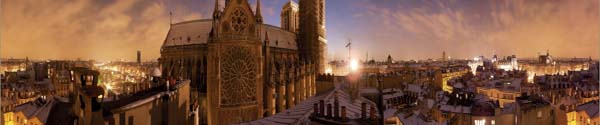
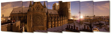
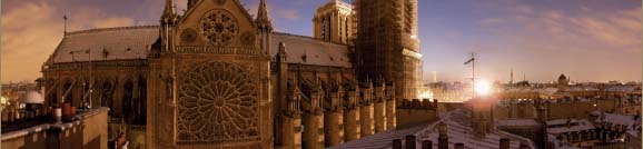
This 360° view of Paris, one of the rare ones I have made, required 22 photos! Because of the lighting conditions, it was necessary to work quickly.
Photo by Arnaud Frich.
The main strength of the higher performing software packages is that they are able to straighten vertical lines and prevent them from converging to a vanishing point if the camera has been tilted while taking the picture. Although the majority of software packages (notably, those sold with small, pocket digital cameras) demand that the horizon line be placed exactly in the middle of the joined photo, others are capable of simulating pictures taken with a shifting lens. This important compositional point in panoramic photography was discussed in Chapter Two.
Angle of View
In joined panoramic photography, the photographer determines the angle of view, by deciding to join a greater or lesser number of images. In this way, if desired, one could make a complete turn of 360°. With certain software packages it is possible to choose from two joining procedures up to 115°. Beyond this, the assemblage will inevitably be of a tiled pattern, since all the horizontal lines, with the exception of the horizon, will be curved.
Having a great deal of experience with rotational cameras, I tend to use the joining method in the same way as my Noblex – that is to say, with a 150° angle of view. Experience has taught me that when I am moved by the scene in front of me, it is rare to be as moved by that scene when it is considered as a 360° image. (However, there always are exceptions; one only has to look at the 360° photographs of France by Franck Charel, made with a Roundshot, to be proven wrong here. But he also would be the first to admit that his photographs require a lot of touching-up.) In Paris, for example, I rarely have wanted to make joined photographs; as I mentioned before, an angle measuring around 150° is what works best for me. And, as if by coincidence, this angle approximates the field of human vision.
A common use of joined panoramic photos involves making an image that will be viewed in an interactive window on the Internet. This is a quite justifiable need to preview a complete rotation; however, the Web-surfer will still be visually confronted with a normal, 4:3 image on the screen.
Focal Length
If I have a bone to pick with swing-lens cameras (e.g., Noblex, Widelux), it is because they do not allow you to choose the focal length of the lens. On the other hand, numerous rotational cameras (e.g., Roundshot, Spheron, Eyescan) and flatback cameras (e.g., Linhof, XPan, Cambo Wide) allow a choice between quite a few lenses, sometimes shifting ones as well. One of the big advantages of joined panoramic photography is that one has even more control over the focal length being used. And because the photographer can start and stop the panorama where desired, from left to right, all that remains is to decide upon the vertical angle of view in changing the focal length. If one often orients the camera vertically, with the shortest possible lens focal length, in order to gain height when photographing entire monuments, numerous situations also exist where a longer focal length would be preferred. Using wide-angle lenses, the image quickly is dominated by large areas of sky and earth, which are often without interest. It is not always necessary to chase after the shortest focal lengths! For example, good 35 mm lens is often well-adapted for landscapes, even in the city.
Tilting the Camera
Generally, most photographers do not think to tilt the camera when making a joined photograph since it is highly advisable to keep the ball-and-socket joint level while turning it, and the lens squared in relation to the horizon. But certain software programs – unfortunately far too few of them – are capable of correcting converging lines caused by the tilting of the camera; the goal is to simulate the shifting of a lens. With the others, the horizon line will have to remain right in the middle of the joined image. If one wants to place it elsewhere for aesthetic reasons, it will be necessary to crop the image. As a result, the image will be noticeably shorter in appearance.
Software packages that accept photos only where the horizon line is perfectly centered make it impossible to use a shifting lens. Far from being joined correctly, in the latter case, the horizon line would be transformed into a succession of curved waves at each overlapping area, since it would no longer be located in the middle of the final image.
With Autopane Pro, ImageAssembler from Panavue, Stitcher 5.0 from Realviz or PT Gui, one easily obtains a flat horizon line without shifting lenses, almost anywhere in the photo (on the condition that the horizon line remains visible in the viewfinder when taking the picture), and very straight, nonconverging vertical lines (notably, with architectural photography). This is absolutely amazing! With these software packages, the control is nearly total. For someone like me who likes to shift, this has been a wonderful discovery. In this way, the Autopane Pro instead of the Realvis Stitcher 5.0 not only allows one to avoid buying a shifting lens, but above all, to place the horizon line where desired, no matter what focal length is being used.
It is very easy to tilt the camera around the entrance pupil with the new Manfrotto 303 SPH head.
Leveling
If one is lucky enough to have a tripod with a level, or better still, a Manfrotto 303 head with 300 stand, leveling is very easy. In the case of a custom-built assembly, it is necessary to make sure that the rotational axis is leveled. Here, one can use a simple level, placing it on the flat part of the horizontal axis of rotation. Then, it is necessary to verify that the camera lens is equally squared up – at least when the joined image is not going to be made with one of the rare software packages that allow for perspective correction.
Depth of Field
Due to the overlapping of the joined areas, all images need to be taken with the lens set to the same critical focus. For example, one should not focus on a foreground subject in one picture and at infinity in another. If the photographer wishes to have a maximum depth of field, he or she needs to place the critical focus at the hyperfocal distance, as is done when using a rotational camera. To control how much will be in focus, depth of field is adjusted by stopping down on the lens more or less and by focusing on the hyperfocal distance.
In addition, the size of the sensor or format affects the depth of field, as we saw in Chapter One. The panoramic photographer who seeks the largest possible depth of field therefore will want to choose a small-sized sensor or small-format camera rather than medium or large format. We also saw in Chapter One that the larger the sensor or film format is, the more it becomes necessary to use a long focal length lens to achieve an equivalent angle of view. But the longer the lens focal length is, the more one has to stop down on the lens to reach an equivalent depth of field. For example, in panoramic photography, it’s quite common to stop past f8 with a 35 mm or digital camera, and down to f45 with 4 × 5. And once again, with digital sensors, it is difficult to obtain enough shallow depth of field when wanting to emphasize a certain plane.
How Many Images?
The number of joined images depends on the choice of focal length, orientation of the camera (horizontal or vertical), amount of overlap, and angle of view. Again, the overlapping between images will need to be around 20 percent; in other words, each image will have a usable area of about 60 percent (100 – 2 × 20). For obvious reasons, it should never go below 50 percent, but the exact amount ultimately is not all that important. Personally, when I contemplate the joined image prior to taking the picture, I make sure that the important areas are placed in the middle of each component photograph rather than at the seams. If need be, I am happy to take one or two additional photos, especially if I anticipate a more important overlap elsewhere, between two other images. And it is not necessary that the amount of overlapping be the same. In any case, if the final image turns out to be more spread out than previously imagined, recropping it later will be very easy.
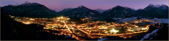
Photo by Bertrand Bodin.
Here is a simple formula to have an idea of the number of photos to take, relative to the desired final image:
N = F/(60/100 × HFV)
N = number of images to make
F = field of view of the panorama
HFV = horizontal field of view of the lens
The horizontal field of view is the angle of the scene embraced by the lens as measured from left to right, whether the camera is in a vertical position (i.e., for portraits) or a horizontal position (i.e., for landscapes). But be careful, since catalogues nearly always refer to the angle of view as measured along the format diagonal. A simple rule of three allows you to easily find the angle needed:
HFV = AV × WF/DF
HFV = horizontal field of view of the lens
AV = angle of view cited by the manufacturer, for a lens of a given focal length
WF = width of the film or sensor format
DF = diagonal of the film or sensor format
For example, in the case of a 35 mm lens for 35 mm (24 mm × 36 mm) with a diagonal measuring 43.27 mm and a corresponding diagonal angle of view measuring 62°, calculating for the horizontal field of view taken in results in the following:
HFV = 62 × 24/43.27 (portrait position)
or again:
HFV = 62 × 36/43.27 (landscape position)
Therefore,
HFV = 34° (portrait position)
and
HFV = 52° (landscape position)
Returning to the first formula, and still in the case of a 35 mm lens for the 35 mm film format, to make a 160° panorama with the camera in the portrait position, calculate as follows:
N = 160/(60/100 × 34)
which would be
N = 7.8
or roughly eight images.
To correctly juxtapose two consecutive images in a joined panoramic photograph, they must be taken from the same point of view, or in other words, a vantage point where the perspective does not change. In this way, the foregrounds and backgrounds will superimpose in the exactly same manner between two consecutive photos, no matter what the direction of the camera. This point commonly is called the nodal point. Although a rotational camera can be said to turn upon the nodal point source of the lens, it turns upon another point when using the joining procedure: the entrance pupil of the lens. This is the most important technical point to remember in joined panoramic photography.
Thus, an ideal point of rotation exists in the lens, depending on its focal length – or focal lengths for a zoom lens – and the camera must turn around this point in order to achieve perfect image overlaps. But rest assured, complex calculations will not be needed to find it. In fact, it’s very simple, since the operation can be performed on the LCD screens of pocket digital cameras, or better still, in a reflex camera’s viewfinder.
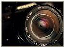
The entrance pupil of the lens is found on the plane of the aperture-diaphragm, as viewed from the front of the lens. With a zoom lens, one can see this plane recede or advance in the lens barrel, in changing the lens focal length. Thus, in this case, the entrance pupil is not always found on the same plane, since there can be any number of them in a zoom lens. Determining three or four of these points here will be enough.
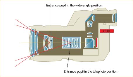
Cutaway view of a digital camera: the position of the light rays’ point of convergence (i.e., the entrance pupil) changes as focal length of a zoom lens changes. Warning: with certain recent zoom lenses, the point of convergence is found at the same position for two different focal lengths (e.g., the 24 mm[-]70 mm/f2.8 Canon L).
For a given focal length, the rotational axis of the ball-and-socket joint needs to line up with the entrance pupil. Using a modified, perpendicular carriage system, discussed in the section dealing with panoramic tripod heads, it becomes necessary to shift the camera with the ball-and-socket joint until the entrance pupil is placed above the rotational axis. We will now address this in more detail.
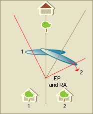
When the lens’s entrance pupil (EP) and the ball-and-socket joint’s rotational axis (RA) are superimposed, the perspective does not change.
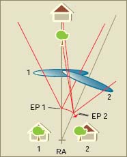
When the lens’s entrance pupil (EP) and the ball-and-socket joint’s rotational axis (RA) are not superimposed, the perspective changes. The entrance pupil shifts to the right in this example, changing the perspective since the point of view is not exactly the same. It’s as if one had moved slightly to the right.
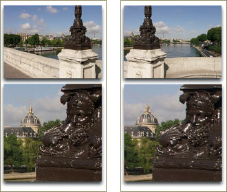
This series of photos was taken while placing the lens’s entrance pupil just above the ball-and-socket joint’s rotational axis. The streetlight in the foreground remains in same position relative to the dome in both exposures.
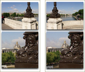
This series of photos was taken while placing the lens’s entrance pupil outside of the ball-and-socket joint’s rotational axis. The dome in the background shifts, since the perspective has changed.
The joining is perfect and does not show any visible connections.
Here is the typical kind of flaw noticed in a joined panoramic photo where the camera did not rotate around the entrance pupil. The software has chosen to combine the foreground perfectly but displays two superimposed images in the background.
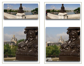
The two series of images are to be joined with the joining software. Note that the horizon line is located in the exact middle of each photo. Therefore, this assemblage is representative of limitations encountered with all the software packages on the market.
The outcome is unavoidable: the software blends the foreground and background of the two adjoining photos together. Here, I have decided to enlarge the lamppost in order to illustrate the example. And the result speaks for itself. In any case, a certain amount of retouching will need to be anticipated since photos containing foreground elements will not line up perfectly. It is obvious that had there not been a foreground element, the assemblage would not have been as difficult.
Determining the position of the entrance pupil is easier than it appears. There are two ways to achieve this, the second being used as a verification of the result given by the first. Since it is necessary find a vantage point from which the perspective will no longer change, looking through a stationary reflex viewfinder or LCD screen will be enough. This viewfinder method is the first and simplest method. Once the entrance pupil has been situated above the rotational axis, foreground and background elements are checked against each other by turning the panoramic tripod head. Adjust slightly, until the perspective no longer changes. Thus, one finds where the entrance pupil is located for the lens or focal length in question. All that remains is to do the same check at other areas where pictures are to be taken.
The paper diagram method, which requires a piece of paper, serves to fine-tune the first method and further verify the position of the entrance pupil.
Viewfinder Method
Regardless of whether it would be with the useful Manfrotto panoramic tripod head or a homemade arrangement, the steps involved in locating the entrance pupil of a given lens focal length have been given earlier. The photos on the opposite page illustrate what is seen in the viewfinder or on the screen when determining the following:
1. Level the tripod at the chosen point of view. The rotational axis should be absolutely horizontal, whether it is a Manfrotto head or a homemade arrangement.
2. Attach the camera to the Manfrotto QTVR head or a homemade arrangement and verify that it remains level when turning 180° to 360°.
3. Shift the camera from side to side so that the optical center, seen from the front, is lined up above the rotational axis.
4. Select the focal length if using a zoom lens.
5. Find a significant foreground object or vertical line six or more feet away, and verify that intelligible far-off objects are also present.
6. Place the foreground object or vertical line on the right-hand side of the viewfinder or screen and take a close look at its position in relation to the objects in the background.
7. Turn the camera to the right in order to place the same foreground object or vertical line to the left of the viewfinder or screen.
8. Determine whether there has been any movement of background objects in relation to the foreground.
9. If movement is detected, shift the camera from right to left, or from back to front, on the ball-and-socket joint until the foreground and the background no longer change position in relation to each other. (Make sure that the alignment is like that of the photo in Figure 5.29.)
Step 1.
Step 3.
Step 9.
As long as a shift between the foreground and background can be observed, the entrance pupil is not placed at the rotational axis. Therefore, it is necessary to advance or withdraw the camera support (shown in Figure 5.29) until this difference is eliminated.
As mentioned in the section dealing with equipment, you have to make sure that the sliding platforms are long enough if you own the more recent zoom lenses. With these, complex optical formulas place the entrance pupil far from the tripod mount of the camera.
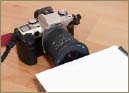
To have a precise idea of the entrance pupil’s location for a given focal length, or to confirm the result of the viewfinder method, two sheets of paper, a ruler, and a magic marker are all that is required. To begin, stop down on the lens and view it from the front: inside, you can easily see the plane where the aperture, or the entrance pupil, is located. If it is a zoom lens, you can also see how it moves back and forth in changing the focal length.
1. Place a piece of paper just in front of the lens of a given focal length. Make sure that the paper, while lying flat, is supported and raised to the diameter of the lens (see Figure 5.31).
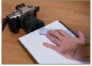
2. Close one eye and line up the other with the edge of the paper while looking toward the aperture.
3. Move the eye along the right side, staying at the level of the paper, until you no longer see the aperture.
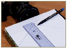
4. With a marking pen, mark out two points on the paper: one right next to the lens, where the remaining aperture blades can be seen, and the other on the edge of the paper where the eye is located (see Figure 5.32).
5. Do this again, on the left side of the paper.
6. Connect the points to form two lines leading from each side, then extend these lines onto another piece of paper. The entrance pupil for the focal length in question is found at the intersection. Measure the distance between the edge of the overlaid first sheet and the intersection of the two lines on the second and note where this distance is located on the lens barrel (see Figure 5.33).
Entrance pupil viewed from the front.
Step 1.
Step 4.
Step 6.
This measurement needs to match the result obtained by the viewfinder method. By rechecking the information, both measured and observed, it is possible to exactly determine where the entrance pupil is located for a given focal length. (Thanks to Emmanuel Bigler and Yves Colombe for this information. I obtained it from the following Web site: www.galerie-photo.com.)
As mentioned earlier, this important axis of rotation will be located at different places on the camera, depending on the focal length and the angle of view.
Importance of the Entrance Pupil
I am often asked if it is absolutely necessary to place the entrance pupil above the rotational axis. The reply is clearly no, it’s not obligatory. For me, the most important thing is to make photographs, be they technically good or not, and not to obsess about one particular technical point. However, I do not see how one can make a sequence of beautiful photographs without being concerned about the manner of taking pictures.
The further away the subjects are, as in a beautiful but distant horizon, the less of an issue the entrance pupil will be. However, placement of the rotational axis at the entrance pupil is critical in overlapping image areas where there is both a subject in the foreground and another much further away. There, a small difference in perspective will be quickly noticed.
To make a hand-held distant landscape panorama, I recommend turning around the camera rather than remaining in the same place and turning the camera around yourself. The joining software will also be less difficult to use this way.
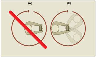
When making a hand-held photograph, turning around the camera is necessary, rather than the opposite. Seen from above, the camera seems to turn around a single point on the ground. © Realvis
If you want hand-held images that are joined very smoothly, you will practically always have to make panoramas of far-off subjects, without any foreground. Although highly efficient, the joining software is not capable of miracles!
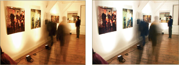
The photo on the left has been taken under artificial lighting with a white-balance reading of 6500 K (similar to daylight film). Colors are very warm and saturated. By adjusting the balance to 3500 K, the colors appear more natural.
Photos by Arnaud Frich
Light metering is perhaps the most difficult task in the joining method. To repeat, this is all about taking a series of photographs in which the color and luminosity differences need to be as small as possible in order to aid the assemblage. In terms of light quality, one color temperature must be selected for all the images, overriding the automatic white-balance. Then, in terms of light quantity, the metering of the light-level will depend largely on the type of assemblage chosen. And the larger the angle of view, the more difficult this will be to determine. The range in contrast between different parts of an image can be very significant when the angle is very wide, especially in nice weather since the shadow and highlight areas will not receive the same amount of light. Sometimes the entire difficulty lies in balancing these differences.
There are only two categories of color transparency film, daylight and tungsten. These cover all types of lighting scenarios, apart from color negative film, which is treated as a slightly different case. Thus, the photographer does not have much of a selection, but this is not a problem that pertains specifically to panoramic photography. (As it exceeds the bounds of this book, I will not enter into further detail concerning these choices; rather, I refer you to the bibliography in Appendix A.)
On the other hand, with digital photography it is possible to accurately select the color temperature, but in no case should the white-balance be left in automatic mode since this would result in overly large color shift between component images. It is important that an object or an important colored area be placed in one photo, rather than allow it to overlap into the following, so that the sensor can apply a color correction to an isolated image. In this way, one photo in the series could have a dominant warm or cold tonality, whereas the others would be neutral. And once the color temperature has been chosen, it will be necessary to leave metering in the manual mode for the other images as well.
I do not really care for the idea that with digital photographs one can erase the color temperature characteristics of certain illuminated areas. Therefore, I have a tendency to use my digital camera like a traditional camera by setting the color temperature to 6500K, except when the weather is really cloudy. In the latter case, raise the level to 7500K to avoid completely removing the dominant bluish cast of the image. In the evening, after sunset, I often work at 4500K, which allows for a nice balance between twilight and artificial light. In this way, I achieve a balance between natural and artificial light that resembles color transparencies made with daylight-balanced film (Fuji Provia 100F).
It’s really a new thing in color photography to be able to select the color temperature without needing a color temperature meter or a large collection of Wratten color correction filters.
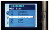
Disengage the automatic white-balance and select a color temperature depending on weather conditions or your own personal taste.
The photographic rendering of a white surface depends on the light and the kind of film being used. It will appear blue in cloudy lighting conditions and orange with halogen lighting and daylight film. Using artificial lighting and tungsten film, it appears white again. Actually, this film is much more sensitive to the blue radiation of the lighting, which compensates for the larger amount of orange radiation coming from a halogen or tungsten light bulb. The white-balance of a digital camera precisely determines the light quality striking and illuminating a subject, balancing this so that a white sheet of paper will always appear white on a screen. It’s as if one had an infinite variety of film.
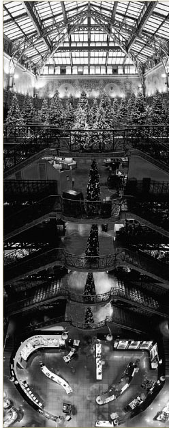
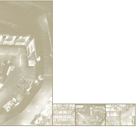
Photo by Arnaud Frich.
Two possibilities are available for determining the exposure of a series of images used in an assemblage: hand-held light meters and those that come with the camera, of which certain kinds (e.g., dot matrix measure, ESP, multizone) work quite well. Taking incident readings with a hand-held light meter, which is very reliable, is equally recommended when conditions allow it (uniform light or sunny weather). From the start, it’s just about taking a general reading to obtain a couple of exposure/f-stop combinations as points of reference. Then, if conditions allow it, one measures the difference in contrast between the different areas of the panorama (from right to left or from exterior to interior). These differences increase as the angle of view widens; and to measure these, I heavily recommend using a built-in spot meter – or even better, a hand-held spot meter.
In the matrix or ESP mode, take a general reading from the start, then slightly correct the exposure between each view if this is required.
One crucial point concerning exposure with either a sensor or film is the loss of noticeable information in areas having too much or too little exposure. With a digital camera or color transparency film, the choice of the exposure depends on the highlights, which should not be too blocked-up, or overexposed. With color negative film, the opposite holds true: it’s the shadows that should not be too underexposed. Returning to digital and color transparency film, if the highlight areas are properly exposed and the shadow areas are a bit too dark, it will remain possible to fix this with the retouching software. The amount of correction depends mainly on the quality of the sensor and scanner involved: the larger the capacity of the sensor the more it will be possible to lighten underexposed areas without introducing digital noise, or interference. With negative film (color or BW), one cannot improve upon underexposure: if the information is not recorded on the film, there will be no way to invent it. On the other hand, it is theoretically possible to minimize a slight overexposure of the highlights by underdeveloping the film. But in the end, this is not very practical; if certain exposures on a roll of film require less development, still others do not. Therefore, it usually is necessary to rest content with making slight compromises during exposure, rather than profiting from subtle gains in later development.
Localized Metering – Differences in Contrast
The panoramic photographer working with assemblage is confronted with two types of exposure problems. One is the need to balance the main differences in contrast from one end to the other of the panoramic photo; the other is balancing an interior in relation to an exterior, for example when photographing a room opening onto a landscape. In this way, whenever one photographs a large expanse, as is often the case with panoramic photography, the main differences in contrast appear between the left and right areas of the image (except, perhaps, in the case of overcast or foggy weather). Typically, one area will be in the sun while the other will be in the shade. And this difference in contrast is best metered with a built-in or hand-held spot meter, since the area measured is very specific.
In joined panoramic photography, it is customary to expose all the photos at the same exposure setting in order to avoid differences in illumination in the overlapping areas. But today, software packages are capable of balancing small shifts in illumination by fusing the sky’s illumination in two consecutive photos. Thus, it will be possible to make corrections of up to a third of a stop in certain pictures. The easiest example is one in which the areas from left to right range from sunlight to shade. By applying an exposure correction of a third of a stop between each image over a dozen pictures, the cumulative correction will be close to three stops. In full sun, this often will prove to be quite enough. And such corrections will not always be needed in balancing a photo.
A typical example of a panoramic photo with an interior is a bit different, since here it is more about preventing the openings (windows or doors) from being too overexposed – something that is inevitable if one wants to expose an interior properly. An easy trick consists of making two sets of pictures: one for the interior and the other for the exterior. After this, they are put together (e.g., in PhotoShop) using masks to blend them into one whole seamless image.
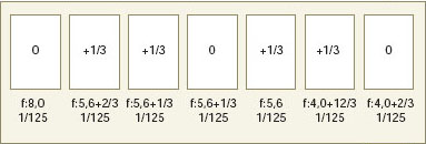
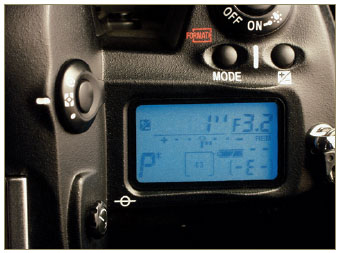
Example of exposure corrections during rotation: a correction of 1/3 of a stop takes place between certain views.
Using the spot meter in the camera, if it has one, makes it unnecessary to use a hand-held one. Not only will the measurement be more precise than with the automatic or program modes, but one will also be able to avoid under- or overexposing an area or areas in the image where it is necessary to hold onto information – in other words, the shadows and highlights. In this way, only overexposure with color transparency film and digital cameras and underexposure with negative film (color and black-and-white) are irreparable with the retouching software, as we remarked earlier. Therefore, it is necessary to be constantly vigilant.
Keeping the previous section in mind, one suspects that far from remaining idle at the side of the camera, the panoramic photographer choosing the joining method will actually have a lot of work to do in taking the picture. Perhaps it will be slightly correcting the exposure between photos – something that is more difficult with hand-held photography – or watching out for changing light conditions. In other cases, dodging an intense light source during one or two photos will be called for, to avoid a halo or other unsightly reflections. Also, one will have to remember to turn the camera between each picture!
Seen from above, the camera makes a rotation around the entrance pupil between two consecutive views. The angle depends on the focal length used.
The angle of view of the final image is determined while setting up. Then, all that remains is to revolve the camera between pictures – which depends on the angle of view of the focal length used – while considering the amount of overlap needed between each image. As I have already shown in the section devoted to equipment, with a rotating Manfrotto stand (reference no. 300N) all that is needed is to turn the camera one notch after taking the picture. The positioning is done by eye, by means of a screen or a viewfinder. Sometimes I even find that aiming with the eyepiece has some advantages when the camera does not have a built-in mask. With certain cameras like the Olympus E10/E20 or the Canon EOS 1 RT, the reflex viewfinder has a semitransparent mirror; if sunlight or a spotlight enters the viewfinder, it will completely fog the photo, as I can bitterly attest from experience.
Exposure correction is a delicate step, demanding a certain amount of concentration. During light metering – especially when determining the contrast range – a decision is taken regarding exposure corrections that will result in significant differences in exposure from right to left of the image. And this, as we have seen, requires an adjustment of no more than a third of a stop between each component image.
On the other hand, I also recall that as the exposure is made in the manual mode, it is also necessary to make exposure corrections either by altering the opening of the aperture, if one wants to emphasize a constant shutter speed (e.g., in freezing motion, as is the case with a waterfall), or by changing the shutter speed, if one does not want to alter the depth of field. Once again, this is a matter of compromise – a technical or aesthetic decision.
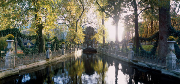
Photo by Arnaud Frich.