It’s been a long journey, but we’ve reached our final project in this book. The previous four projects focused on practical uses for the Tinker Board, but for the grand finale we’re going to stray a bit from the practical and build a simple robot that can be operated via a custom Bluetooth controller and will stream video.
Why a Robot?
A robot is the quintessential electronics project. Robots come in many varieties and can be very simple or incredibly complex. By now you’re well aware of the Tinker Board’s features, and once again the Internet connectivity, full operating system, and diverse IO options beyond GPIO make it a great platform for a robot with more features than your average beginner robot.
Robot Supplies
For the construction of the robot, we’ll be using two DC motors with wheels attached to a mini robot chassis. If you want to use a different motor type, such as gearbox motors, you can. The concept will be the same. For the chassis, there are countless options available on the market, and the one you choose really comes down to personal preference since its purpose is to hold the electronics and attach the motors. Different shapes, colors, or materials won’t affect the robot’s technical outcome.
To keep everything mobile, the Tinker Board will be powered by a USB battery bank, which will be mounted to whatever chassis you choose. You’ll need a high-capacity battery bank, especially with the Tinker Board’s amperage concerns. Luckily, these larger capacity battery banks are becoming more common and are also available in smaller sizes. Because of this you will probably get better power results with the original Tinker Board than the Tinker Board S, since the Tinker Board S needs 3A to boot.
Of course, something needs to control the motors, since hardware PWM is not available on the Tinker Board’s GPIO and is a necessary feature when it comes to controlling motors. As a result, we’ll be using another HAT, this time by Adafruit, specifically the Motor HAT. Additionally, we’ll use their Python library for the HAT, which will make coding the motors’ movement a lot more straightforward.
Adafruit was mentioned in the GPIO chapter as an option for procuring electronics supplies. In addition to selling standard electronics components, they’re also an open source hardware company in the United States that designs, manufactures, and supports a variety of boards produced in-house.
I2C
The HAT communicates with the Tinker Board through I2C (Inter-integrated Circuit, pronounced “I squared C”), which is a serial communication protocol that is very similar to SPI in that it allows for multiple integrated circuits to communicate with each other. However, I2C requires only two pins to communicate with multiple devices; by contrast, SPI requires four pins for each connected device and a dedicated IO pin from the master device for each connected device. I2C-connected devices are also a bit easier to manage and don’t require as much setup as SPI.

The Adafruit Motor HAT
Robot Extras
To give our robot some extra flair, we’re going to implement a camera into its design. We’ll use either a webcam or a camera module connected to the CSI connector on the Tinker Board, like the one we used in the Android chapter, to stream a video feed to a webpage on your network while we drive the robot around. We’ll be able to mount the camera to the front of the robot chassis and have it act almost like the robot’s eyes.
Speaking of driving around, we’ll need to control the robot, and this creates a great opportunity to build a custom controller that communicates via Bluetooth. To do that we’ll use an additional Adafruit development board that’s Arduino-compatible (meaning that you can code it using the Arduino IDE and Arduino code libraries), called the 32u4 Bluetooth Feather.
But if you don’t want to build a custom controller, you don’t have to. We’ll be controlling the robot with keyboard inputs, so our custom controller will be a macro keyboard in disguise. As a result, you can use the same wireless or Bluetooth keyboard you’ve been using the whole time with your Tinker Board.
This entire project will again take place in TinkerOS. So, let’s begin by booting into TinkerOS and setting up the Python library for the HAT.
Motor HAT Setup
Let’s begin the setup for the Motor HAT by following the steps outlined by Adafruit to install the Python library.1 First, we’ll need to change directories to the Home directory and install the dependencies, most of which should already be installed if you’ve been following along with the other chapters.
After that finishes, change directories into the newly cloned folder with cd ~/Adafruit-Motor-HAT-Python-Library. Once in the folder, we have a Python setup script to run. In the terminal, type sudo python setup.py install.
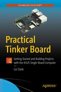
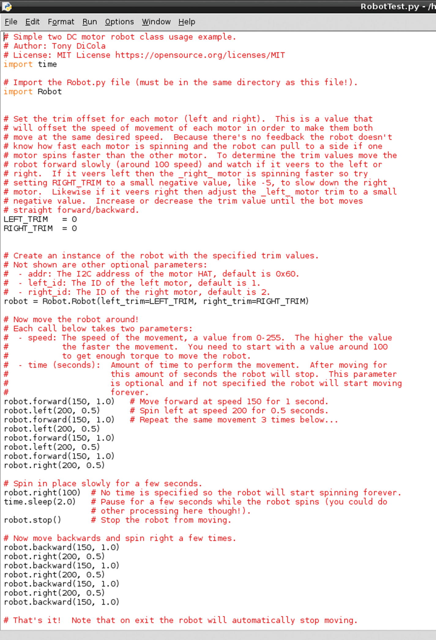
The Robot.py library file
The main takeaway from Robot.py is that it has functions written to define the pulses for the motors for different speeds and directions. This means that when you write your own code with Robot.py imported, you can use simple commands like robot.direction(speed, time) , where you enter a direction parameter, speed parameter, and then how long you want your robot to do that action, and your robot is on the move.
As you can see in Figure 11-2, the files for this library have very detailed comments explaining what each line is doing, which you can read at your leisure if you need to clarify anything.
Connecting the Hardware
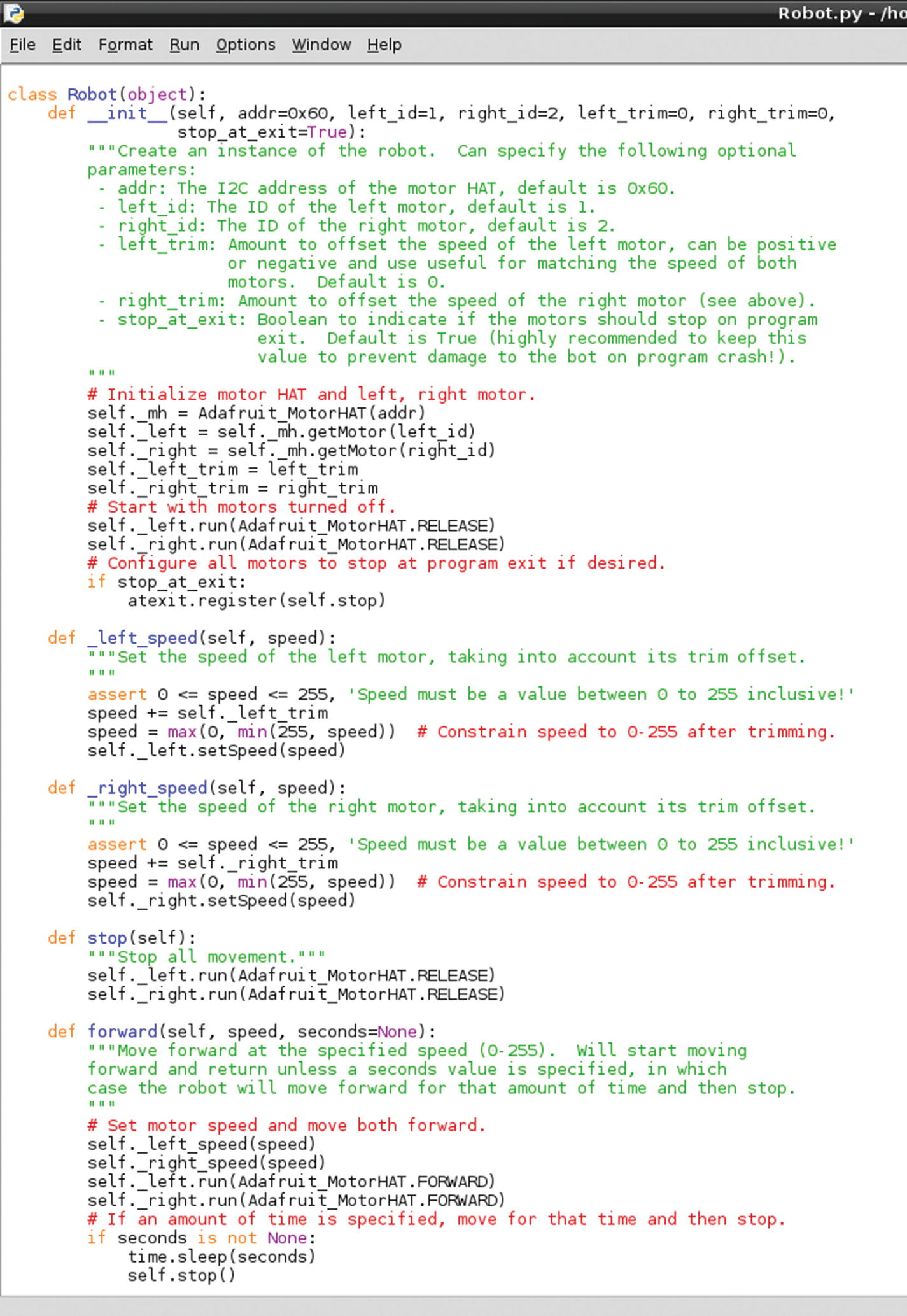
The motors connected to the terminal blocks on the Motor HAT. You’ll need a small screwdriver to tighten the terminal blocks.
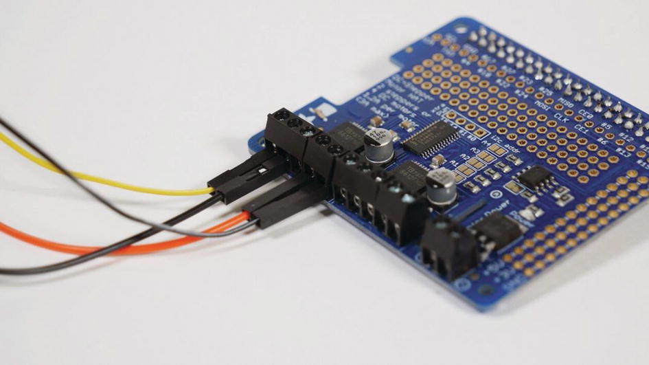
The power terminal connector for the motors on the HAT
Running the Example Code
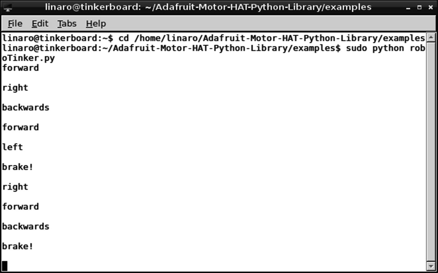
Once everything is connected to the Tinker Board, the demo code we’re going to try is RobotTest.py . It basically has a sequence of commands to make sure everything is hooked up properly by pulsing the motors at different PWM frequencies. Each sequence is on a timer without a loop, so the script runs through once and then stops.
To run it, while still in the examples folder, enter sudo python RobotTest.py into the terminal. Your motors should start spinning for a few seconds each at different speeds. If you run it with your robot fully assembled, you’ll also see that it’s going backward, forward, left, and right.
The RobotTest.py file
Then we can see how the different motor movements are called using the same syntax that we discussed earlier: robot.direction(speed, time) . That’s basically the entire script. The Robot.py library file makes it very simple to program in motor movements. Let’s move on now to starting our robot project code.
Robot Project Python Code
When you’re beginning to write code for any project, it’s important to break the process down into the basic goals that you want to accomplish, as we did when planning the EPD project in Chapter 10. In its most basic form, we want our robot to be able to go forward, backward, left, and right and to stop. Each of these directions will be controlled with a button, which points us in the direction of using if statements; for example, “if this button is pressed, have the robot do this.”
To implement these controls, we’re going to use keyboard inputs. This way, you can either use your attached keyboard or build the upcoming custom Bluetooth controller, which will send the same keyboard commands. The camera portion of the project will be separate from the Python code. With everything planned, we can start writing our code.
In Python, you can have keyboard inputs affect code execution by using the readchar library . It’s installed using pip , so you’ll need to change directories to the Home folder and enter pip install readchar into the terminal to install.
To break that if statement down, if W is pressed, then the robot will move forward at 75% speed. The string forward will also be printed to the terminal for troubleshooting purposes and there will be a slight delay to keep everything running smoothly. Since the script is going to be waiting for keystrokes, the delay will avoid any lag or scenario of commands running into each other in an infinite loop. If the delay is set to be too long, however, you will experience a noticeable lag.
Note
An important point about the readchar library is that anything that you put in the (key == ' ') parentheses is case-sensitive. As result, if you want just a simple keystroke to be read, be sure to keep the enclosed letters lowercase.
The confirmation strings that the roboTinker script has received the keyboard inputs for control
Configuring the Camera
We’re going to take a break from the Motor HAT for a moment and work on the camera portion of this project. We’ll be using a camera, either a USB webcam or a ribbon cable camera, as essentially a set of eyes for the robot to navigate with.
The camera feed will be streamed with a piece of software called MJPG-streamer, which allows you to receive a video feed from a device on your network, in this case the Tinker Board, via a browser. You’ll have to be on another device on the same network to receive the stream, but it should at least allow you to explore your home without leaving the couch.
Webcam vs. Ribbon Cable Camera
The CSI-cam connected to the Tinker Board
There are pros and cons for each camera choice. For the webcam, you’ll more than likely get better picture quality, and a USB connection is easier for hot-swapping peripherals; but it is much larger than a camera module, and you’ll have to manage the longer USB cable when assembling your robot. The housing for the webcam may also create issues with mounting the camera to the robot chassis.
The camera module is a much smaller form factor than a webcam, and you can either purchase an aftermarket case for mounting it or create your own using 3D printing or CNC. The ribbon cable can be swapped for different lengths to best suit your project, and plugging directly into the top of the Tinker Board can also help to keep things tidy. However, the camera module will have a lower picture quality than a webcam and often requires a well-lit area to have the best results. The MIPI connector is also finicky on both the camera module and the Tinker Board. Additionally, the camera module is highly sensitive to static shock and should only be handled in a grounded area. The connectors and ribbon cables are also very fragile, so the entire camera must be handled with care.
As you can see, the camera type you choose will come down to your goals for the robot and personal preference. Luckily, the same software can be used for either choice, so let’s move on to setting up MJPG-streamer.
Installing MJPG-streamer
to install them.
After that we’ll use subversion, which we just installed, to download MJPG-streamer from the server location where it’s hosted. With the terminal, enter svn co https://svn.code.sf.net/p/mjpg-streamer/code/ to download the folder into the Home directory.
After downloading, change directories to the new folder using cd ~/code/mjpg-streamer. MJPG-streamer utilizes a make file to install, so while in the directory enter make followed by sudo make install into the terminal. Once the installation completes, you’re ready to try MJPG-streamer.
Running MJPG-streamer
To use MJPG-streamer, you of course need to connect your chosen camera device. This needs to be done while the Tinker Board is powered off, because during boot, the Tinker Board will detect that the camera is connected and create a video device under /dev; otherwise, your camera will not be recognized. Once your camera is connected, power up the Tinker Board and via the terminal change directories to the MJPG-streamer folder with cd ~/code/mjpg-streamer.
From the folder, we’ll run the MJPG-streamer program. There are a few configurable parts for MJPG-streamer. The first is calling MJPG-streamer, with ./mjpg-streamer. Next you select an input device and settings with -i "./input_uvc.so -y. Here the UVC video plug-in is initialized as the video input, and -y indicates that the YUYV video format will be used over MJPG.
-r sets the resolution; and since we’re streaming, a lower resolution will guarantee smooth video via the network.
640×480 is an option that balances between image quality and streaming quality. Of course, you can use a resolution as high as your camera supports.
-f sets the frame rate, or FPS, for the video, and depending on your region and goals for the project this may vary. 30 FPS will create a very smooth picture.
Finally, -n blocks the initialization of the dynamic control features (dynctrls) in the Linux-UVC library. This will depend on your camera and its drivers, but you have a lower chance of throwing errors if you disable it.
Combined, the entire input portion will be listed as -i "./input_uvc.so -y -r 640x480 -f 30 -n".
Next is the output portion, basically how the video is being pushed to the stream on the network. It begins with -o, followed by "./output_http.so for streaming with the HTTP plug-in, followed by -w ./www" so that the files will be written to the web page for the stream rather than a subfolder, and as a result are not saved anywhere.
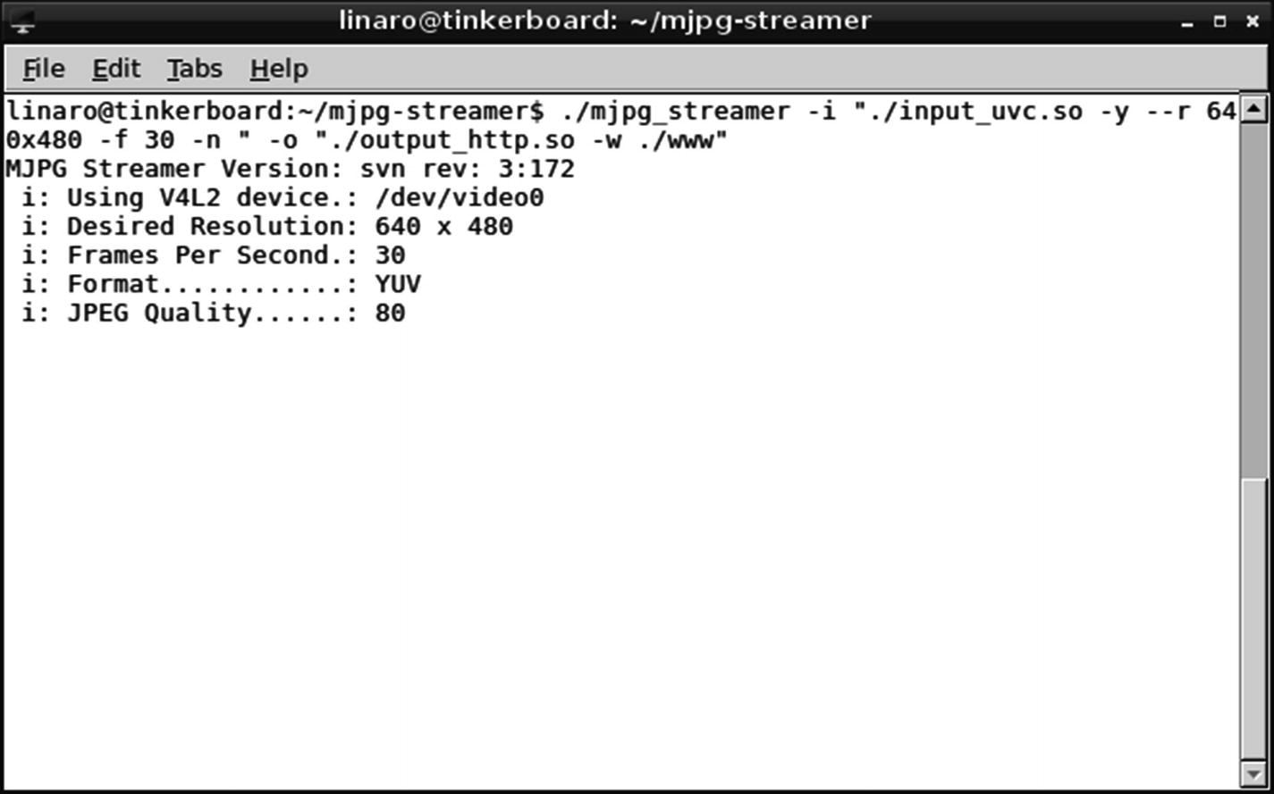
MJPG-streamer executed without errors via the terminal
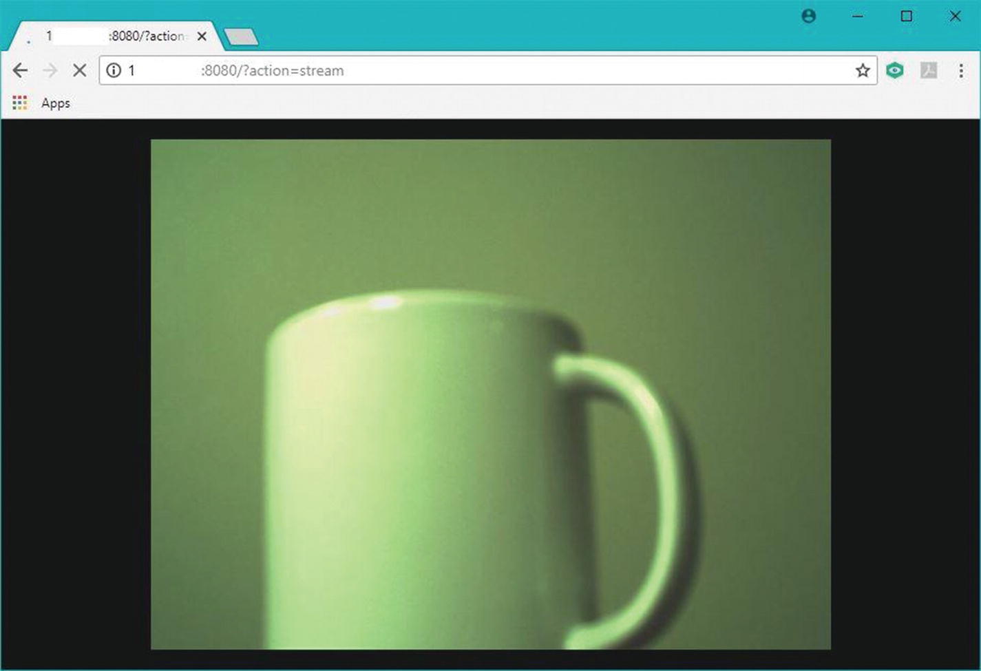
The MJPG-streamer streamed live in a browser on the network. The camera feed seen here is from a ribbon cable camera module.
Start on Boot
Much as we needed to have our EPD project start up on boot, we’ll do the same thing with our robot so that we don’t have to worry about an HDMI connection interfering with our chassis. We’re going to target the same network folder, if-up.d, for MJPG-streamer, since it requires a network connection. MJPG-streamer is terminal-based, though, so how will we have it launch without typing into the terminal? We’re going to use a type of script called a Bash script. You can put anything that you would normally type into the terminal in a Bash script to have it run as an executable file.
For our roboTinker Python script, we’re going to launch it from a file called autostart , which is in the .config/lxsession/LXDE folder path. It contains other commands related to the GUI that need to begin on startup, but unlike the files located in if-up.d, they do not require a network connection and you don’t need to be root to access the folder and file.
Bash Script for MJPG-Streamer
To create our Bash script for MJPG-streamer, we’ll first need to create a new text file. To do this we’ll enter sudo nano start_streamer.sh into the terminal. This creates and enters into a text file called start_streamer.sh. In our blank text file, we’ll first enter our line to make it executable. This is similar to the line that we’ve entered at the top of our Python scripts previously. The technical term for this command is a shebang, because it begins with #!. The shebang syntax for a Bash script is #!/bin/bash.
Once you have that in the text file, save and exit the nano editor , which will bring you back to the terminal. Now, much as we’ve done with Python scripts, we’ll use chmod to make our Bash script executable. Enter sudo chmod +x start_streamer.sh into the terminal and then sudo ./start_streamer.sh to test. If all has gone well, MJPG-streamer should begin running.
Copying start_streamer.sh to if-up.d
After we’ve made start_streamer.sh an executable, we can move it to the if-up.d folder. Before we can do that, though, we need to remove the .sh file extension from the filename, because files with file extensions cannot run in the if-up.d folder. Rename the file to start_streamer via the GUI and then we can copy it over to the if-up.d folder.
Note that the file location for the file to be copied is listed first, followed by the target file location, which in this case is if-up.d.
Launching roboTinker.py with autostart
Previously with our EPD project, we copied our Python files into if-up.d so that they would run on startup once a network connection was established. However, since we’re using readchar for inputs in our roboTinker.py file, it needs to run in the terminal because readchar does not work when executed through IDLE. As a result, we’re going to use the command lxterminal inside the autostart executable to run roboTinker.py via a terminal window that will open upon startup and remain open to receive our readchar commands.
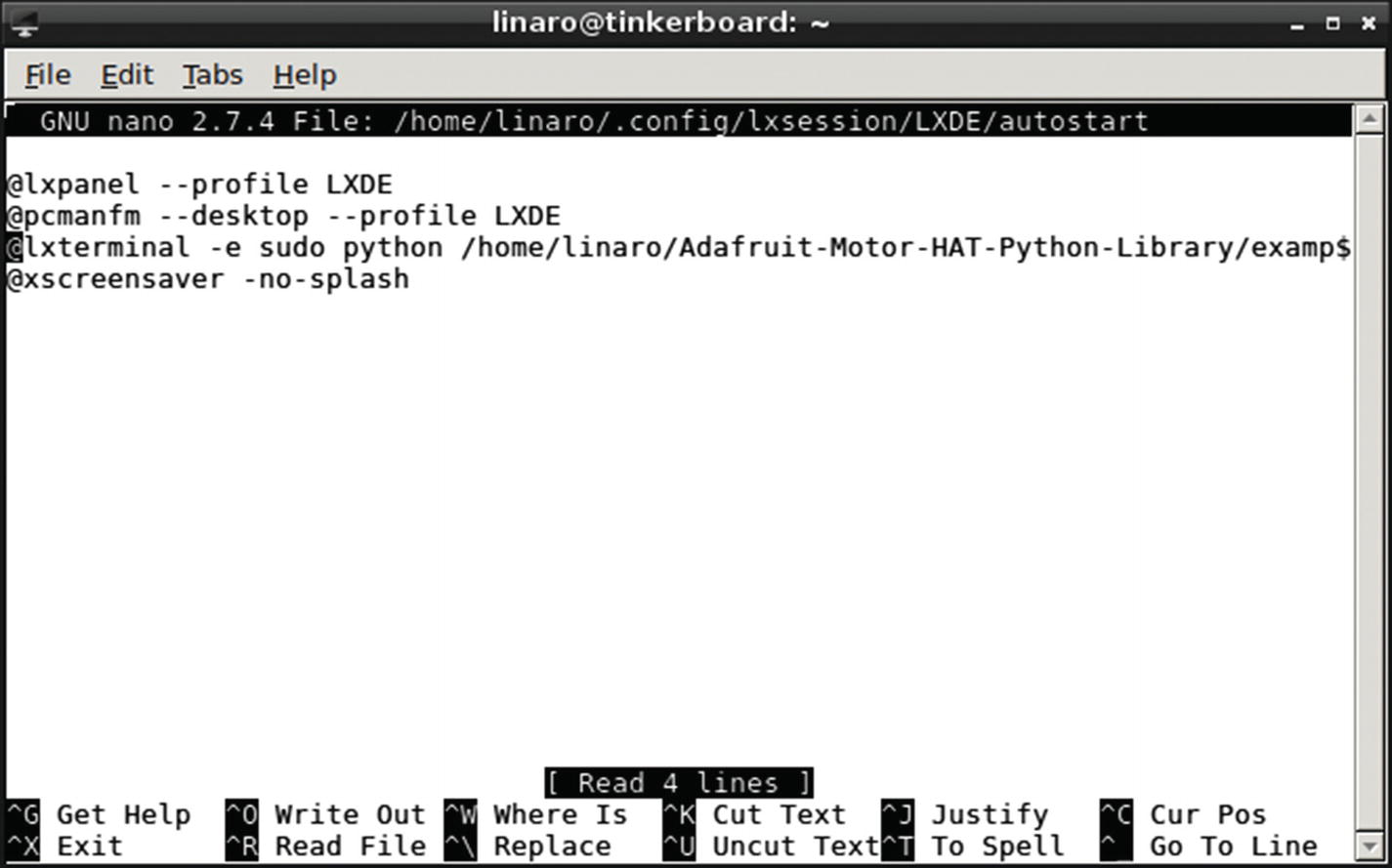
The edited autostart file
Bonus: Bluetooth Controller Coded with Arduino IDE
As a bonus project to accompany the robot, we can also build a custom controller as discussed earlier in this chapter. One of the great things about DIY electronics and maker projects is that they can have multiple components and involve as many different platforms as you want.
For our custom controller, we’re going to be using a 32u4 Bluetooth Feather development board by Adafruit, the same company that made the Motor HAT we’re using to control the motors for our robot. This board can be coded using the Arduino IDE, which is the official coding interface used with Arduino boards.
The 32u4 processor used on this Feather board can act as an HID device without a firmware switch when coded with the Arduino libraries for it. There is also a BLE Arduino library from Adafruit available, along with example code, that we’ll be able to utilize for this mini-project. We’ll just add some minor edits, specifically the GPIO pins and keycodes, to the example code and then be ready to use our controller.
where both arrays are set to have five items. The order matters for both the digital pins and keycodes, where the first index in each array will be paired; meaning that digital pin 5 will send a keystroke for B, pin 6 will send D, and so on. This aspect of the code will all depend on how your circuit is set up.
Circuit
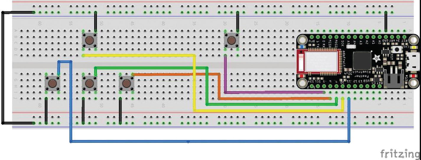
The circuit diagram for the BLE controller
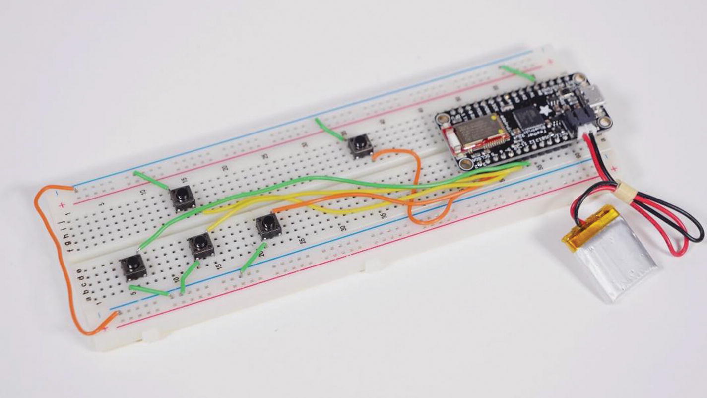
The breadboarded BLE controller. Notice that the buttons are arranged to mimic a keyboard layout with the brake button off to the side.
Since the Feather board can directly plug in a LiPo battery for power, the project can be fully wireless and resemble a controller’s shape while still living on a solderless breadboard. Of course, more experienced users can create a more polished and final version by soldering the circuit to some protoboard and creating a case, but this iteration will certainly get the job done.
Once your circuit is assembled, we can load up the code from the Arduino IDE to the board and connect our new controller via Bluetooth to the Tinker Board.
Connecting the Bluetooth Controller to the Tinker Board
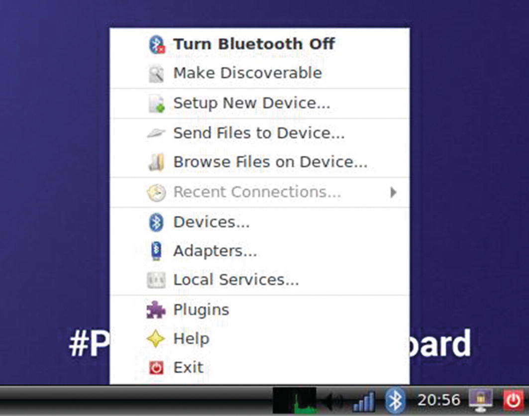
The Bluetooth options in TinkerOS
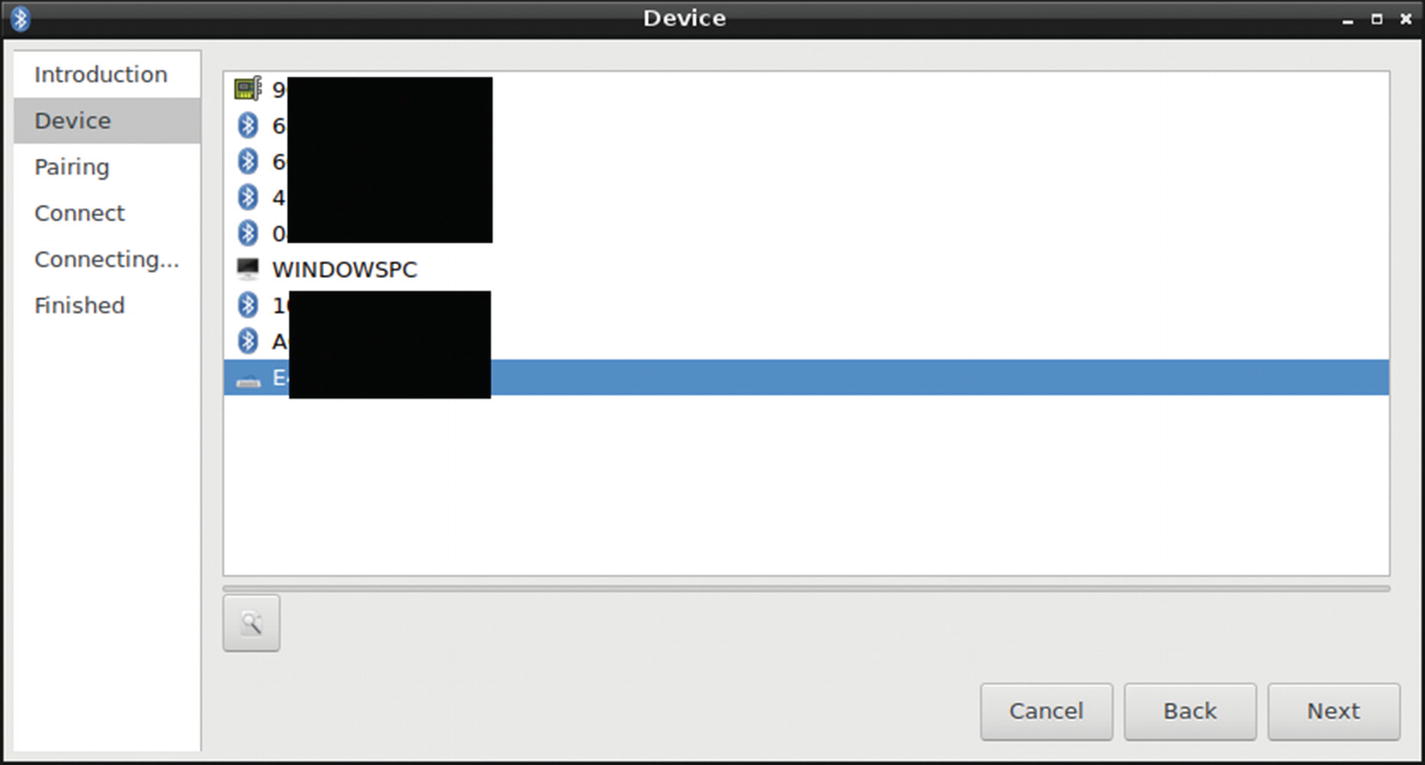
The available BLE devices. Notice the keyboard icon for our BLE controller. The MAC addresses have been blacked out for privacy.
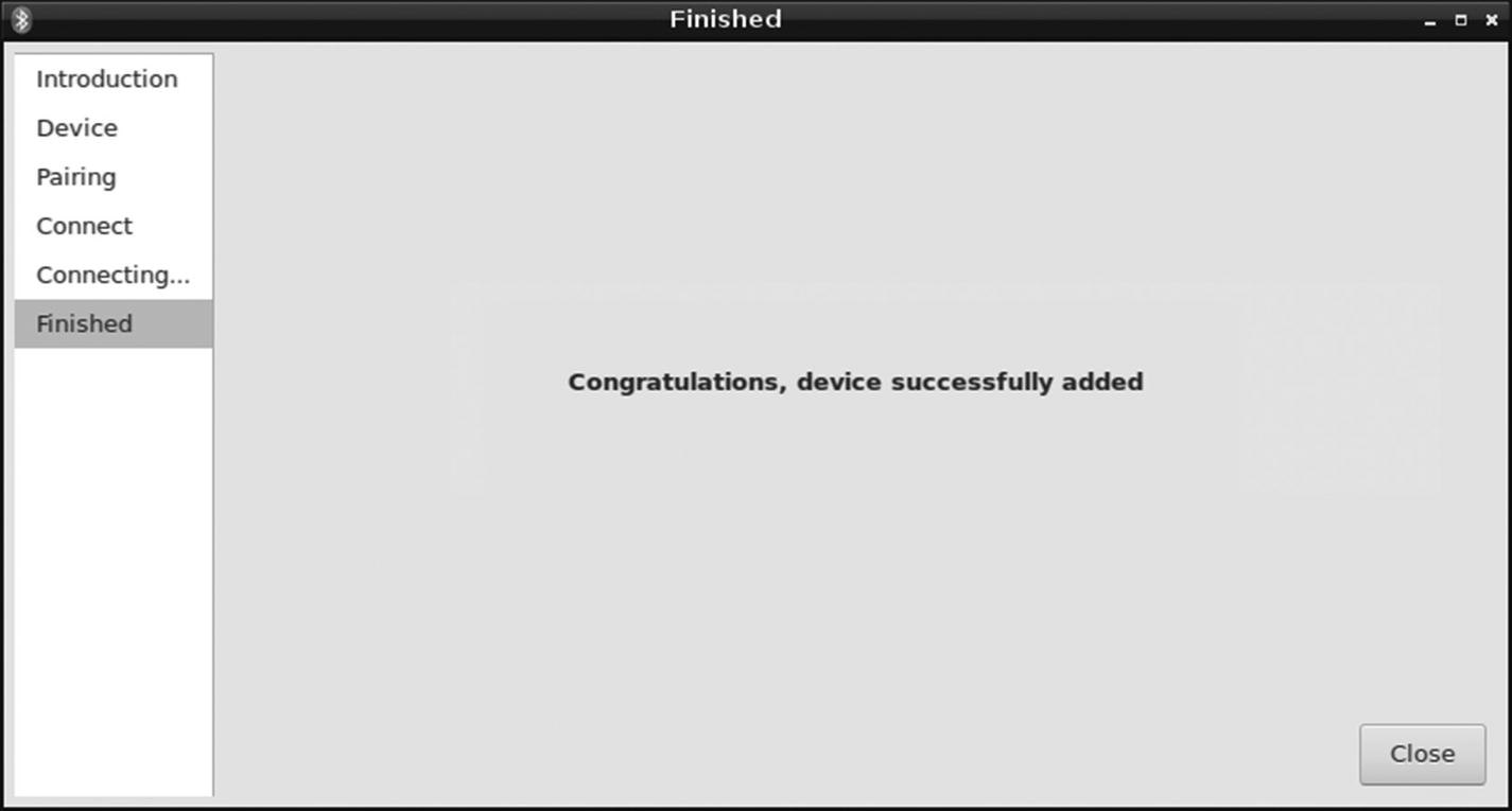
The BLE controller has been successfully paired to the Tinker Board!
Note
The BLE controller will automatically reconnect to TinkerOS after reboots and shutdowns, so you shouldn’t have to go through this process again unless you purposely disconnect it.
Robot Assembly

A fully assembled Tinker Board robot. You can go for any aesthetic you want with your assembly. If you leave the zip ties uncut like the robot in the picture, it can appear to have little antennae.

The Tinker Board mounted to a robot chassis with stand-offs
Wire management is also very important here, since you’ll want to keep your wire routing for all components neat and out of the way of any motors. Everything should be tightly secured, but not too tight; you want to avoid any strain that could cause damage over time. For the battery banks, especially the USB one used for the Tinker Board, you can use Velcro and zip ties to safely secure them and their accompanying cables.
Once everything is assembled on the chassis, you can power up the Tinker Board and Motor HAT, log in to the MJPG-stream on a browser, and begin to drive your robot around.
Final Thoughts
This project is probably the most impractical of the projects in this book; however, it’s assembled with a lot of practical components ranging from Bash scripts to hardware communicating over I2C and even a custom BLE controller. Hopefully this and all the previous chapters have given you the tools to not only get started with the Tinker Board, but truly explore it and use it confidently.