We’re almost ready to dive into using the Tinker Board. But before we do that, we need to go over a few very important accessories that will allow you to have a successful experience.
What Do You Need?
As mentioned in the previous chapter, single-board computers arrive with all components installed, so no additional computer hardware modules are needed, besides storage. However, other vital accessories are needed in order to use the Tinker Board properly.
Cooling
The first, and one of the most important, is included in the box. It’s the heat sink for the SoC processor. For the processor to operate properly, a heat sink needs to be installed. The heat sink included with the Tinker Board is a good size and will offer proper cooling for everyday use. This method of cooling is called passive cooling , since heat is being expelled without an active force directly applied, such as air or water.
You may have used other single-board computers in the past without a heat sink. For lower-powered boards, that is usually fine. However, as mentioned in the first chapter, the Tinker Board is more powerful than many other single-board computers; it has an SoC that is found in consumer products such as Android phones and Chromebooks. With an SoC of this power, a heat sink is not optional. Without it, you may experience thermal throttling, which occurs when a processor cannot perform to its full potential because of overheating. If it operates in this state for too long, it may even damage the SoC and make the board inoperable. It’s the electronics equivalent of not giving a plant any water. So please, cool your board responsibly.
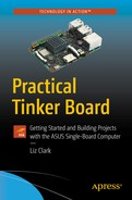
Installing the heat sink is simple. On the back is a thermal pad with a sheet of protective plastic. Simply peel off the plastic and stick the thermal pad to the processor. Apply some pressure to ensure good contact between the thermal pad and the processor. After this, the heat sink should be firmly attached to the Tinker Board as shown in Figure 2-1.
An overhead view of the installed heat sink that is included with the Tinker Board
Other Cooling Methods
Of course, you aren’t limited to this stock heat sink. You can also investigate other, aftermarket heat sinks, if they fit the die size of the processor. This could be helpful in various ways. For example, you could install a shorter heat sink to fit into a housing for a project or a larger heat sink if you know that your project will need better cooling than the stock heat sink can provide. Aesthetics can also motivate a heat sink swap if this will be a visible component in your project and you’re going for a certain look.
Heat sinks can also be applied to other ICs on the board, such as the GPU or even RAM if you want to ensure optimal cooling and performance for high-demand projects. The process for applying a heat sink to these ICs would be the same as applying one to the processor. You would just need a thermal pad and heat sink that fit the die size.
Your cooling options aren’t limited to just heat sinks, though. You can also attach a small fan, either with a mounting kit or in a case, to a heat sink so that the processor can be actively cooled rather than just passively. This creates a cooling solution similar to desktop PCs that often have a fan and heat sink mounted together over the CPU.
This solution is especially effective when the Tinker Board is in an enclosed housing with minimal natural airflow. You may also want to further emulate a desktop PC’s cooling by having enclosure fans bringing air in and expelling it out through vents. By including fans inside the case, you could also keep the board passively cooled without a dedicated fan attached to the processor’s heat sink.
A more intensive method would be to cool the board with water cooling techniques . This approach is definitely for enthusiasts, and it’s uncertain whether a board of this size and power would really benefit from such an extreme cooling solution, but for an enthusiast who wants optimal temperatures it could be an interesting project.
For this technique, you would need a water block that fits onto the processor’s die, as an aftermarket heat sink must, and then a pump and tubing to carry the water. Distilled water is often chosen for water cooling, but specialty fluids are also sold. There are examples of makers implementing this with single-board computers, but again it’s unclear that the effort and cost associated with water cooling are viable for a piece of hardware like the Tinker Board. There is also the additional risk of a leak with water cooling, but it would be up to you whether the risk was worth it for the possible reward of optimal temperatures combined with the aesthetic and accomplishment of water cooling.
Note
Using a cooling solution outside the heat sink provided by ASUS for the Tinker Board could result in undesired effects or performance. It’s important to do your research for your specific cooling need before installing an aftermarket solution.
Power
Once your cooling solution is installed, you’re getting closer to using the Tinker Board. But you can’t really use the Tinker Board without it being turned on, can you? For this, of course, you’ll need a power supply. Power can be delivered to the Tinker Board in two ways. The first, which is the most common and easiest, is through the micro-USB power port with a micro-USB power supply. It’s important to make sure that your power supply is rated at 5V/2A-2.5A for the original Tinker Board and 5V/3A for the Tinker Board S. ASUS recommends a linear power supply, but people have had success with switching power supplies as well.
It’s important to use a properly rated power supply to ensure that the Tinker Board operates as expected. It has a higher amperage requirement than many other single-board computers because of the power requirements for the RK3288. If you use a power supply that is rated lower than 2–2.5A, you may experience display issues, processing slowdowns, or issues with peripherals plugged into the USB ports. The Tinker Board S will not even boot with a power supply that has an amperage lower than 3A. On the other end of things, if you use a power supply with a voltage rating that is higher than 5V, you may short out the board, since it will be receiving a higher voltage than the components and circuitry are designed for.
Note
On the subject of power, if you’re in a dry environment that can cause static discharge, please avoid touching the circuitry or ICs on the board without being grounded, as you can inadvertently short out a component and render it inoperable.
Advanced Power Option
For more advanced enthusiast users there is an additional option to power the Tinker Board—use the GPIO pins, which will bypass the on-board regulators. If this is done improperly, though, it can short out your board. However, this power method can be beneficial in certain situations and projects, since it provides a more direct power source that is unfiltered and as a result can allow the board to draw a more stable and slightly higher current. But the benefit to this method is also its detriment, since there is no over-voltage-protection like that found with the micro-USB power option. You are connecting power directly to the 5V line. But if you’re feeling brave, you have the electrical experience, and you think you have a genuine use case for it, then you can proceed with caution.
Wiring
First, you’ll need a steady and stable 5V power supply line with no more than 1A. This should come from a bench power supply or another trusted source. You’ll be connecting the positive lead to pin 2 (5V) and then ground to pin 6 (GND) on the GPIO. Each 5V pin can only handle 1A since there is no filtering on these supply lines. If you need more than 1A available (which you probably will), then you’ll need to connect to two 5V pins (pin 2 and pin 4) to have a combined amperage of 2A and two ground pins (pin 6 and pin 9). You can get away with using a single ground pin if necessary, but grounding both connections individually can add more stability to your connection.
Note
The Tinker Board’s GPIO is color-coded to help in easily visually identifying the pins. The 5V pins are red and the ground pins are black, so this will help avoid any mistakes. We’ll be going over the GPIO in more detail in a later chapter.
You’ll more than likely stick with the original, suggested option of using a micro-USB power supply to power your Tinker Board, but it’s always good to be aware of other methods available. One thing you’ll immediately notice related to power is that the Tinker Board does not have a dedicated power button. It is only turned on when it receives power and can only be safely turned off via your chosen operating system. As previously discussed in Chapter 1, the new Tinker Board S does have the option to wire-up a dedicated power button with a power-on header separate from the GPIO. This is done by shorting the headers while power is connected to the board.
Peripherals
Power won’t be the only connection that you’ll have to make to fully utilize the Tinker Board. At least on first boot with TinkerOS, you’ll need all of the peripherals that you’d normally need for a desktop computer. These include a keyboard, mouse, monitor, and possibly speakers.
Keyboard and Mouse Choice
For your keyboard and mouse choice, it’s going to come down to personal preference. You’ll utilize the USB ports to connect them and can choose either a wired or a wireless option. Wireless will give you a bit more flexibility and allow you to have more desk space if your work area is cramped, since you’ll be able to have the keyboard and mouse farther away from the Tinker Board.
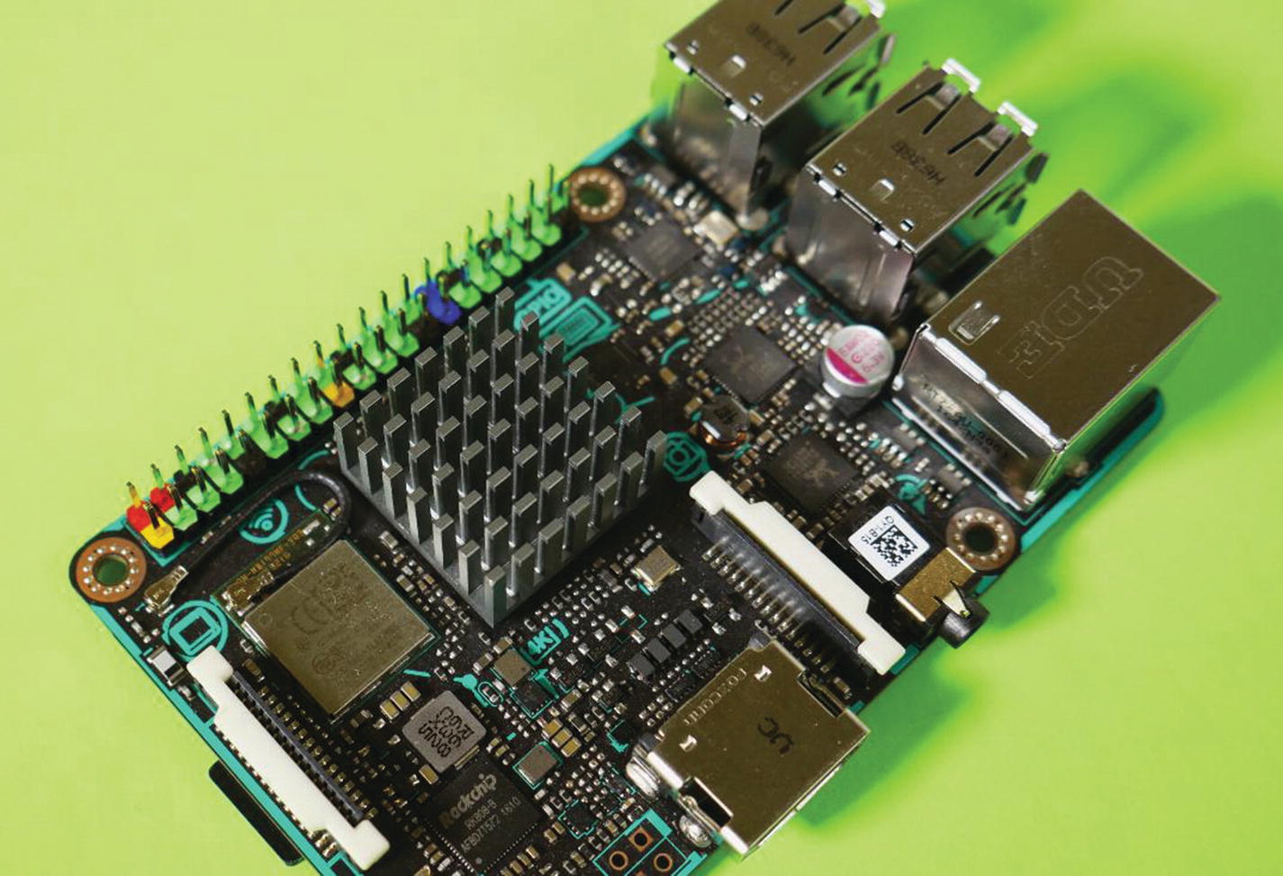
The Logitech K410 wireless keyboard and mouse. Note the single wireless dongle plugged into the Tinker Board.
Monitor and Speakers
Much like the keyboard and mouse choices, what you use for a monitor and speaker solution will be up to personal preference. The Tinker Board has an HDMI output, so a monitor that accepts HDMI would be ideal. Of course, an adapter can always be used if your monitor doesn’t have HDMI as an option. There are many different types of monitors that can work with the Tinker Board, but it all depends on your setup.
If you’re working at a desk, then a traditional desktop monitor should fit your needs, preferably with at least 1920×1080 resolution. If you aren’t planning to have a dedicated workspace for your Tinker Board, you can also use your TV as a monitor. In fact, some projects may make sense to have attached to your TV; especially if they are media or file-based projects.
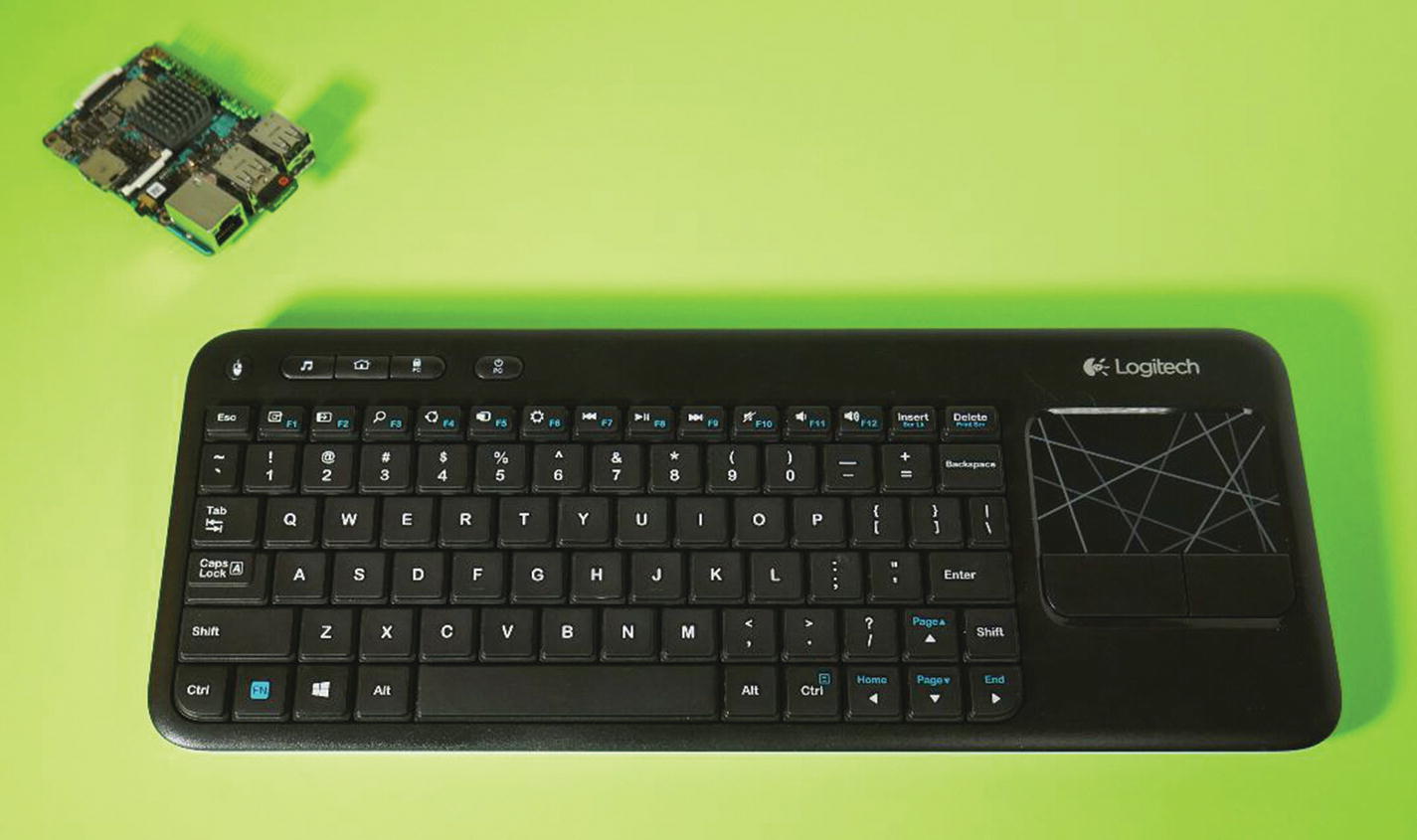
The Tinker Board’s HDMI port and 3.5mm audio jack. To the left of the HDMI port is the Micro USB port for power.
Storage
The last add-on item that you’ll need is storage to run an operating system. Most commonly, a microSD card is used for this purpose. There is an included microSD card slot on the back of the Tinker Board (Figure 2-4), and it is configured to look for bootable media there. The card’s capacity should be at least 8GB for most operating systems. 16GB is your best bet, since it will allow enough capacity for the operating system and any files that you create or need to store without having to add-on additional USB storage. Of course, this will all be determined by your use case, but for the average scenario a 16GB card will be the most balanced solution.
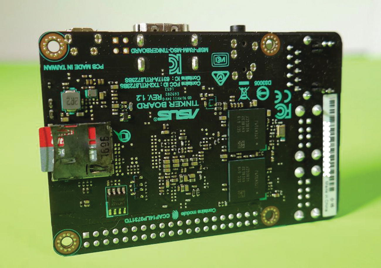
The back of the Tinker Board. The microSD card slot is located on the left side.
eMMC
As discussed in Chapter 1, the new Tinker Board S features an additional on-board option for bootable storage in the form of the 16GB eMMC flash. It has a speed similar to a microSD card on the Tinker Board, since they both utilize the same SD 3.0 speed controller. But because it’s soldered to the board and has a direct connection, it has the benefit of being physically more stable than a removable SD card and in certain applications may be more desirable.
To load an OS onto the eMMC module, you’ll need a micro-USB cable that is capable of transferring data. Plugging the board into your computer will allow the board to be recognized as a removable storage device. You can then load the bootable image onto the Tinker Board for it to be loaded onto the eMMC module. Again, we’ll go over preparing bootable media in a later chapter.
Optional: Cases
One optional item that you may want for your Tinker Board is some sort of case or housing to protect it. The Tinker Board can certainly survive in the wild without any housing, but since it is a circuit board with exposed connections it would benefit from the extra safety precaution.
The options for how you can store your board are almost endless. This is another area where sharing the same form factor as the Raspberry Pi 3 comes in handy, since it means that most cases designed for the Pi can be used for the Tinker Board. The only incompatibility may occur with a case designed to have the processor and heat sink extend from the case, since the Tinker Board’s processor die is larger than the Pi’s. Otherwise, you should find success in cross compatibility.
Types of Cases
Cases are made from many materials. Popular choices include acrylic, plastic, and even metal or wood. For form factors, a classic snap-fit box is very common with cutouts for the different ports. These options are also usually very economical. There are also laser-cut cases that uses layers of acrylic or wood to build up a low-profile case. Some cases are made to emulate classic computer hardware or other pieces of technology. These cases are often more about aesthetics than function, but some do have some interesting features, such as power buttons or routing to have USB ports connect on a specific side of the case.
Incorporating similar features, a recent innovation has been small cases that resemble desktop computer cases. These often stand vertically like PC towers and have air vents, as well as fans and connectors to integrate power and other ports into extensions built into the case for a more compact desktop experience.
DIY options are also available. There are countless files available from makers who have designed their own cases for fabrication with a 3D printer or CNC machine. If you have an interest in either of these hobbies, then creating your own case with one of these methods may be a fun project for you.
Case choice is subjective, and as long as it fits your Tinker Board, then it’s more than likely a good choice. Of course, if your project or application is going to be pushing the Tinker Board’s limits and as a result creating a lot of heat, then it’s important to think about airflow and cooling when considering a case. Some cases also enclose the GPIO pins; so if you’re planning to have access to those, then you’ll want to keep that in mind as well.
Conclusion
This may seem like a lot of accessories, especially considering the size of the Tinker Board. However, if you follow these guidelines you will set yourself up to have the most successful experience with the Tinker Board. Although it may be easy to cut corners on accessories to get up and running, it will more than likely come back to haunt you as you try more complicated projects or different operating systems. It’s best to start off on the right foot so that when you do have to do some troubleshooting you can immediately rule out that you are using out of spec peripherals, storage or cooling solutions.
This concludes the introduction portion of this book. At this point you should have a good understanding of what is making the Tinker Board tick from a hardware perspective, and why a Tinker Board would be used for a project. You should also know what is required for accessories for the Tinker Board to avoid any issues. Now it’s time for the fun stuff: actually using the Tinker Board! Let’s move on to Part II and get to know TinkerOS, the GPIO pins, and Android on the Tinker Board.