
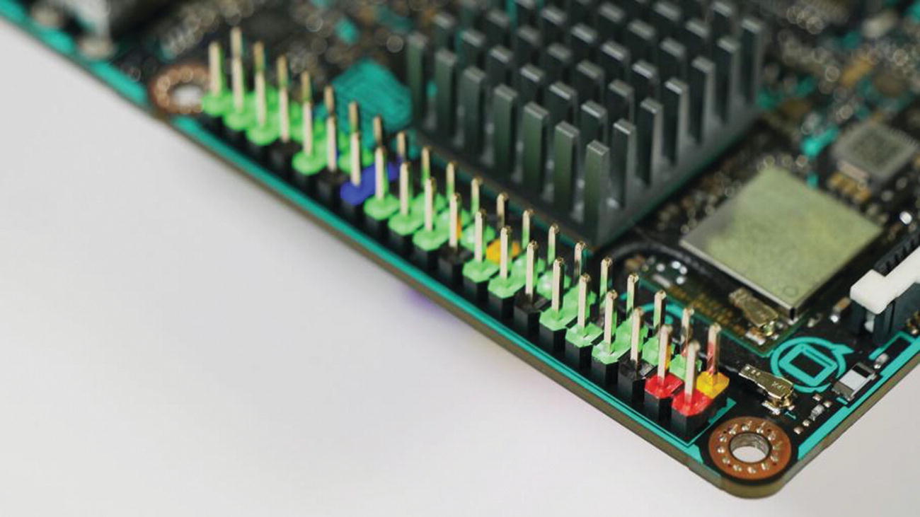
The Tinker Board’s GPIO pins. Notice the color coding on the header to easily identify each pin’s function.
The GPIO pins can be controlled by programs that you can write in either C or Python, the two programming languages we’ve briefly discussed in the preceding chapter. ASUS has libraries available for each language to communicate easily between your program and the GPIO pins. We’ll be installing these shortly via the terminal. To fully utilize the GPIO pins, though, you’ll need some basic hobby electronics components. You may already have these if you’ve worked on electronics projects before, but let’s go through them to be on the safe side.
Gathering Supplies
If you’ve never built an electronic circuit before, this section of the chapter will serve as your crash course into the world of electronics from a practical hobby standpoint, including where to source your components, which components to buy (for the purposes of this chapter), and any other odds and ends you may find to be useful when experimenting with controlling circuits with the Tinker Board. If you’re an experienced electronics tinkerer, you can more than likely sit back and relax during this portion and jump back in when we get to setting up the code libraries in TinkerOS.
Your first question when thinking about electronic components for the first time is probably going to be where you buy this stuff. As brick-and-mortar hobby stores continue to become a rarity, it can be hard to run out and buy these items. Luckily, there are many companies to choose from online to purchase from. Some popular ones include Adafruit, Sparkfun, Mouser, Digikey, and of course Amazon and similar large online retailers such as eBay. Adafruit and Sparkfun offer a more maker-friendly selection of components and other electronic delights, whereas Mouser and Digikey tend to cater to the more professional electronics enthusiasts and engineers; however it can be helpful to keep them in mind when you can’t find a specific part. Amazon offers a wide selection from many different resellers varying in size. Depending on the seller, quality can be varied; so always research and shop smart, especially when it comes to electronics. You don’t want to buy questionable parts because the price was right, only to waste hours troubleshooting temperamental or nonfunctional equipment and parts.
Now that you know where to buy, what do you need to buy? Let’s go over some basic yet necessary parts that will get you started.
LEDs
One of the most versatile and fun electronic components of all time is the humble LED (light-emitting diode). Coming in a variety of shapes and sizes, LEDs can serve a plethora of purposes in a circuit, often serving as a simple indicator or being the main attraction in a large-scale LED matrix display. We’ll be using LEDs more as indicators here, and in fact they’ll play a starring role in our first circuit that we build with the Tinker Board.
Resistors
Another common component is a resistor. Resistors limit the electrical current passing through a circuit. They’re important to protect more fragile components, like LEDs, from receiving too much voltage. Resistors can have different values, which are expressed in ohms and denoted by the different colored bands on the body of the resistor. The value that we’ll use for these circuits is 220Ω, which has two red bands followed by a brown band, as shown later in the circuit diagrams for the examples.
Photoresistor
A photoresistor is a type of resistor whose resistance is determined by the amount of light hitting the sensor. By exposing it to increased or decreased light, you can produce different results in a circuit.
Buttons and Switches
We’ll use buttons to control different aspects of the circuit with code. There are two types of buttons: temporary and latching. A temporary button only affects a circuit while held down, while a latching switch remains engaged and must be pressed again to return to its previous state, like a light switch. The type of button that you use is up to you, but in the circuit pictures in this chapter you’ll see breadboard-friendly temporary buttons and latching switches to easily denote the difference visually.
Capacitors
Finally, another common component is the capacitor. A capacitor , sometimes called a cap, stores potential energy, which is referred to as capacitance. Capacitance can then be added back into a circuit. The cap itself has two leads, which may or may not be polarized depending on the type.
Connecting Your Circuits to the Tinker Board
There are, of course, many more electrical components available than the short list that we mentioned. But with these basic components, we’ll be able to get started programming the Tinker Board and using the GPIO pins to see what the code is doing in real time.
How, then, do we build a circuit and connect it to the Tinker Board for control? First, we’ll need to build the circuit on what’s referred to as a solderless breadboard, or breadboard for short. Breadboards are used for electronic prototyping. They’re plastic trays with evenly spaced holes that are sized to fit through-hole components with 0.1” (2.54mm) pitch, meaning that they have metal leads spaced to fit the pitches of holes on both PCBs and breadboards with that spacing. These holes in the breadboard allow components to contact metal rails that are embedded in the plastic housing, usually in rows, to carry current to each component to have a stable circuit. Breadboards can be found at the same suppliers referenced earlier for electronic components and come in a variety of shapes, sizes, layouts, and even colors.
Chances are that when you lay your components out on a breadboard, they won’t be able to comfortably reach each other to make contact. This is where jumper wires come in. Jumper wires allow you to make the electrical connections between components and the Tinker Board, which in this scenario will be transmitting data, power and ground connections to the breadboard. Jumper wires are specially made to be reused in prototyping situations, since they are of pre-cut lengths and have plastic headers on either end.
There are three types of jumper wire: male-to-male, male-to-female, and female-to-female. Male-to-male is probably the most common, since it’s basically just a piece of wire and can be used to make connections across the breadboard. Male-to-female and female-to-female can extend connections between components that have headers or components that are farther away from each other. We’ll use female-to-male wires to connect the GPIO header from the Tinker Board to the breadboard.
Note
There are GPIO extension cables sold for the Raspberry Pi family of boards that you could use with the Tinker Board since they have the same GPIO pinout. These allow you to use a ribbon cable that has a large female header on one end that fits over all the GPIO pins and male headers at the other end to plug directly into the breadboard. In this chapter, however, it will be assumed that you’re just using female-to-male jumper wire to interface your circuits with the GPIO pins.
Circuit Diagrams
The examples throughout this book will include circuit diagrams so that you can build the circuits accurately. These diagrams were all created with Fritzing, an open source program that allows you to create circuit diagrams to display a circuit in breadboard, schematic, or printed-circuit board (PCB) view. For the upcoming examples we will use the breadboard view, since it allows the circuit to be easily expressed as a picture with the components.
Besides including images for standard components, Fritzing also allows the creation of custom parts that can be used in your circuits and diagrams. A custom Tinker Board part has been created for this book and will be available for download so that you can add it to your Fritzing part library, if you wish, for your future projects with the Tinker Board .
Installing Programming Libraries in TinkerOS
Let’s take a break from hardware for a moment and go back to software. Before we can start coding, we need to install some libraries for the coding languages that can interface with the GPIO pins, Python and C. To do this, we’re going to boot into TinkerOS and open a terminal window to install the libraries using the git clone command to download and clone the repositories from GitHub to your local OS. These libraries will make programming for the GPIO pins very simple, similar to using an Arduino or Raspberry Pi. In fact, the libraries are heavily based or even direct ports of the libraries available for Raspberry Pi.
Installing the Python Library
First we’re going to install the Python library. Python is a general-purpose programming language whose syntax is set up to be easy to read, so users can understand what’s happening in the code at a glance. Because of this, it’s a great text-based programming language to get started with.
Navigate to your terminal window and enter in our favorite commands from the previous chapter: sudo apt-get update and sudo apt-get upgrade . This ensures that everything is up to date, so that when we install our Python library it is set up in the best possible scenario.
After any updates you fetch have finished installing, we’re going to install the Python language packages, which contain dependencies needed to properly code in Python using IDLE, the Python IDE, and the ability to use any extensions within Python. We’ll install the packages for both Python 2.7 and Python 3. To install, enter sudo apt-get install python-dev python2.7-dev python3-dev into the terminal. You’ll notice that we’re installing both at the same time.
After the Python packages have been installed, we’re going to install Git, open source software that allows you to keep track of multiple files in a project so that they can be edited in real time by multiple users on different computers. Git has become an industry standard for code project management. As mentioned previously, these libraries will be cloned from their repositories on GitHub, a popular website used to host projects using Git. To install Git, enter sudo apt-get install git into the terminal.
Note
Entire books have been written on how to use Git to its full potential along with the associated websites, such as GitHub. Here we’ll only be discussing the basic uses that will be necessary for our use case in accessing these code libraries.
You’ll see the installation begin, and after a few moments the Python library will be downloaded to your installation of TinkerOS.
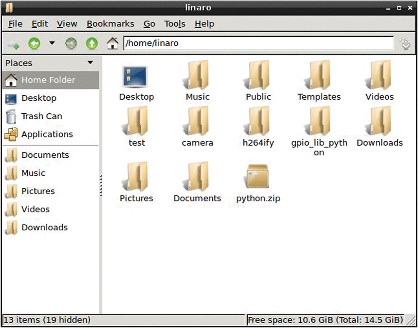
The Python code library folders, both zipped and unzipped, in the Home folder directory

The terminal after changing directories to the new gpio_lib_python folder and running the sudo python setup.py install command
After that finishes running, we’re going to run the script for Python 2.7 and Python 3, by entering sudo python2.7 setup.py install followed by sudo python3 setup.py install .
Blink!
We’re finally ready to build some circuits and write some code. The first example we’re going to look at is commonly referred to as Blink and is considered the hardware version of “Hello World!” It’s a very simple program that will make an LED blink by regularly causing the GPIO’s data pin, which the LED will be connected to, to go high and low (or on and off) repeatedly. It’s a great test to make sure that everything is set up correctly on the Tinker Board for software and to also make sure that your hardware is configured properly as well.
Build the Circuit
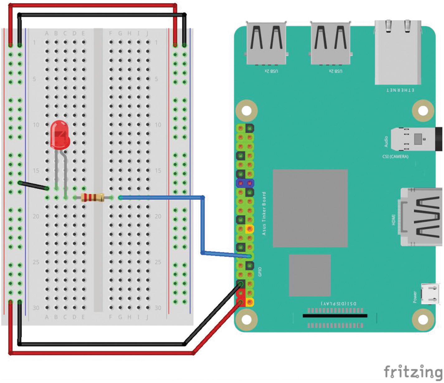
The circuit diagram used to blink an LED. Notice how the 5V and ground rails are set up, as well as the LED’s polarity and connection to physical GPIO pin 11 on the Tinker Board.
Note
Going forward it will be assumed that you have your breadboard wired up like this to power and ground unless otherwise noted.
Now we can take the LED and place it on the breadboard so that each leg is on a different rail. The LED can’t be connected directly to the GPIO pins, though; it needs a resistor to limit the current that can pass through it. Otherwise, the LED could short out and die. As discussed earlier, a 220Ω resistor works well for breadboarding basic LEDs and can be identified by two bands of red followed by one band of brown. Take this resistor and connect it between the positive leg of the LED and GPIO physical pin 11. The LED’s positive leg is the longer of its two legs and is called an anode. Then take the LED’s other leg, which has a negative polarity, and connect it to the ground rail on the breadboard. A negative lead on an LED is called a cathode and is the shorter of its two legs. After you’re finished, your circuit should look like Figure 5-4 .
Writing Python Code
Now that the electronics are wired properly, let’s get into some coding in Python. Navigate to the Programs menu under Programming and open IDLE (using Python-2.7). As mentioned previously, there are a few different versions of IDLE installed in TinkerOS; and we did install the GPIO Python library for both Python 2.7 and 3, but at the time of writing all the code examples that we’re about to go through have been tested to work with Python 2.7.
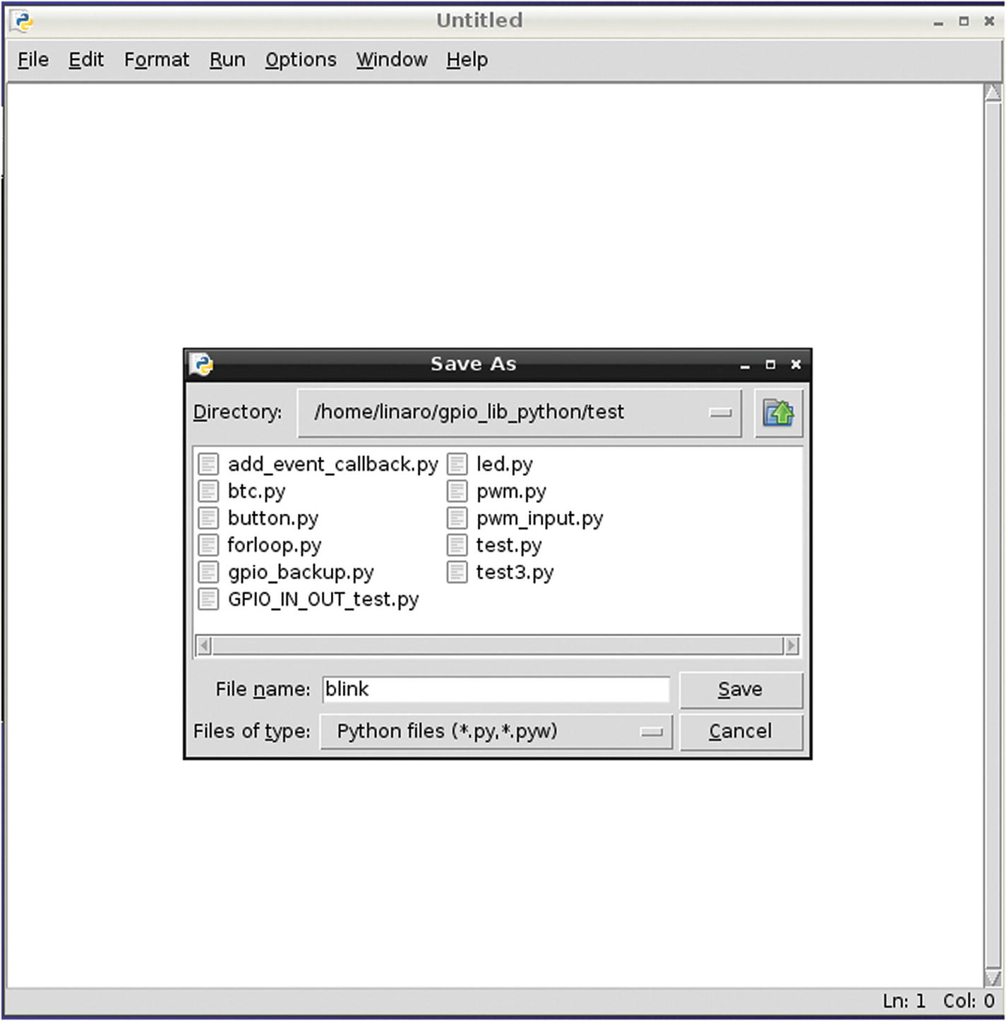
Saving what will become our new Python program to the test folder within the Python GPIO library folder. Notice that we are naming it “blink.”
This turns off warnings about any issues with any of the GPIO pins before the program runs. If a program is exited in an incorrect way (think of turning off a desktop computer by holding down the power button while running multiple applications), then the GPIO pins (or ports when discussing them in terms of the SoC) can become “stuck” and appear to be in use by your system, in this case by TinkerOS. By including that line of code at the beginning of your program you can ignore those errors and avoid frustrations while getting started. Keep in mind, though, that this does not fix the problem and in a best-case scenario you should be ending your programs properly and always fully debugging for long-term program use.
Note
If you’ve programmed the GPIO pins on a Raspberry Pi before, this will be familiar to you since for the Pi there are also two modes: BOARD and BCM, where BCM is the equivalent to GPIO.ASUS. You can bring up a detailed diagram of the GPIO.BOARD and GPIO.ASUS numbers by entering sudo gpio readall in the terminal, as you’ll see in Figure 5-15, after installing the C library, which we will also go through later in the chapter.
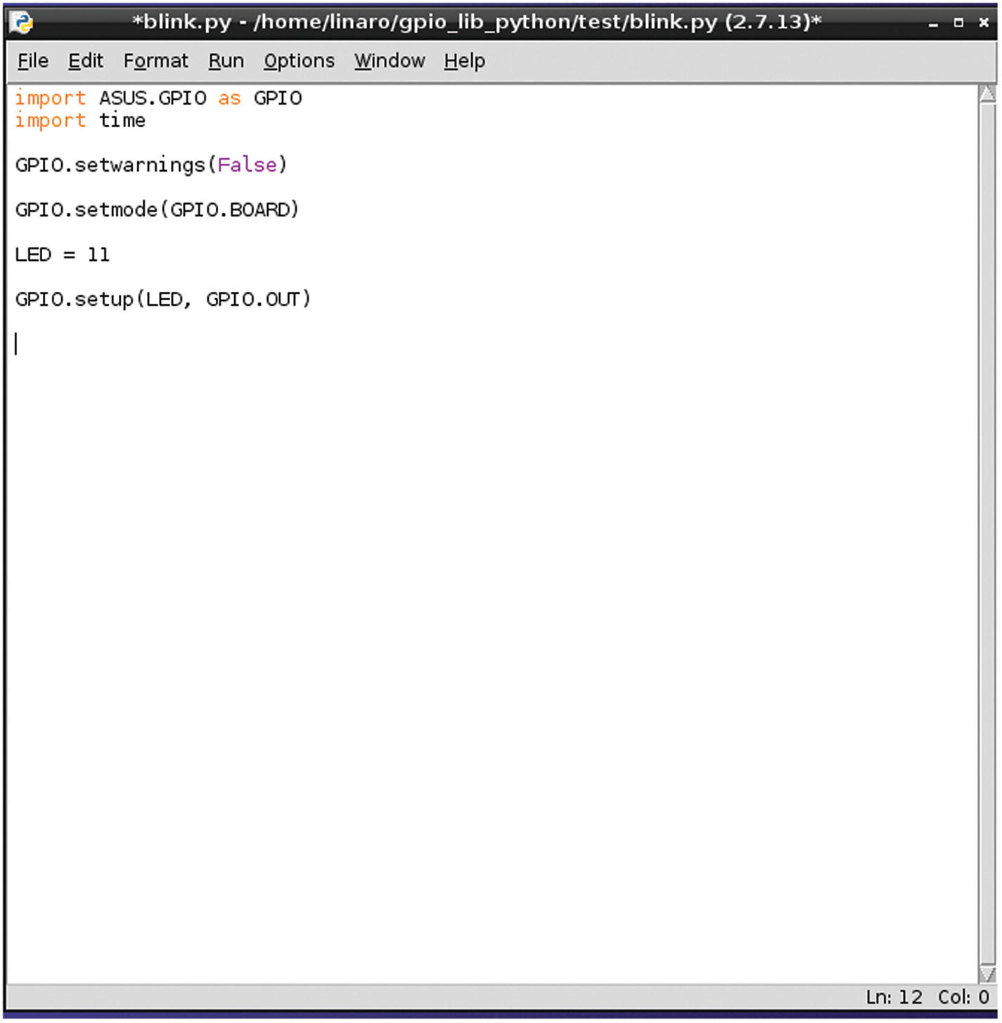
Our blink.py script so far
Here is the first time we’re using the Time library, by adding a delay of one second, so that the LED will be on and off for one second each continually. The print statement allows us to send whatever text is between the quotation marks to the terminal as text. This loop will work on its own, but it will make for better code if we add two more lines.
Congratulations! You’ve written your first Python program on the Tinker Board! Now save your script and let’s move over to the terminal to run it.
Running Your Code
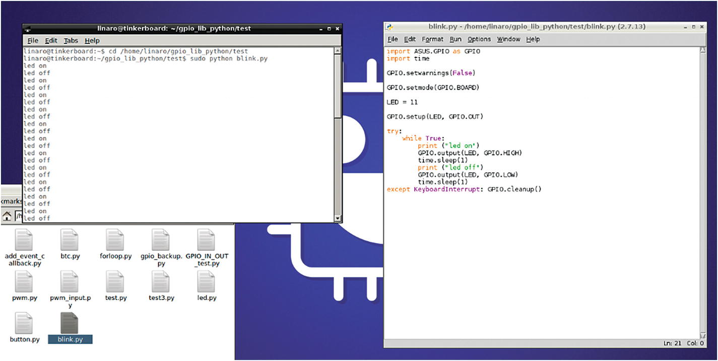
The blink.py program running
Add a Button
Blinking an LED is great, but chances are your projects will require more than a flashing light. We can modify both the Blink program and circuit slightly to have a button control when the LED is on rather than software.
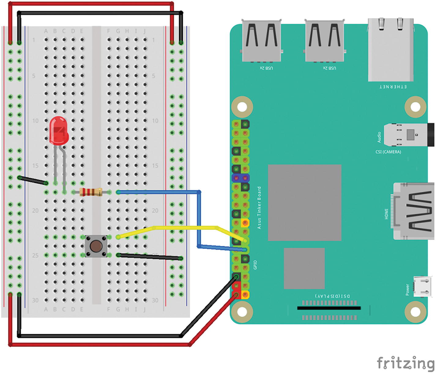
The LED circuit with a button added. Notice that the button is connected to both ground and GPIO physical pin 13 next to the LED
We still want the loop to run infinitely since we want to be able to press the button at any time to turn on the LED. But we’re going to check to see whether the button is being pressed and have the state of the button affect the state of the LED. To do this we will use an if/else statement, which is very common in programming. The logic is defined by having two situations to check for; commonly checking for things like sensors being on or off.
You’ll see that the delay has been reduced to 0.1 second. This makes the response time a lot faster, since if it were to be kept at 1 second there would be a significant delay between when you pressed the button and when the LED finally lit up, and vice-versa. We’ve also added in two terminal print-outs to double check the state of the code compared to your circuit. However, with the decreased delay, please keep in mind that these print-outs will move much more quickly up your terminal.
Note
Notice the indents and colons in the loop. These are integral characteristics of the syntax of the Python language. Using them makes writing code in Python very simple; however, they are quite subtle and can often be missed, especially by a beginner. If you’re having issues with any of your code, be sure to check your indents and colon usage first to avoid long bouts of frustrating debugging.
Since you were more than likely editing your Blink sketch, be sure to save this new program as Button in the same test folder we’ve been working in. After saving it, open a terminal window and change directories to the test folder as we did before. Then use your preferred method of running a Python program from earlier and run the Button.py script. Your button should be controlling your LED, and your debug statements should be quickly scrolling down your terminal.
Switch It Up
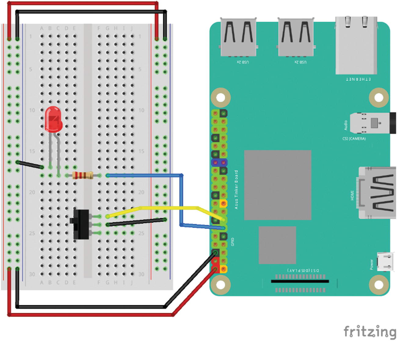
Our button circuit now with a sliding switch
Reading Data
There’s one last example to go over and unfortunately (or fortunately) it doesn’t include an LED. Instead we’re going to switch gears and build a circuit around the humble photocell resistor, which we discussed a bit earlier in this chapter. We’re going to use the photocell to send data to the Tinker Board that will then be displayed in the terminal. This will serve as a good example showing how to hook up other sensors in the future to the board and read data in real time.
There is a caveat in reading this data. The Tinker Board, much like other single-board computers, is incapable of reading analog signals (any signals that do not fit into the basic on or off state), because it has no onboard analog to digital converter (ADC), which is found on microcontroller boards such as an Arduino Uno. There are ICs available to do this on a circuit level, but that would begin to take us into more advanced circuit building and programming realms, which are beyond the scope of this chapter.
With all of this in mind, how are we going to read analog data from a photocell resistor? This is where another basic component, a capacitor, comes in. We’re going to use a 1 μF capacitor to receive and hold voltage from the GPIO pin that the photocell resistor will be attached to.
Since the photocell is basically a variable resistor whose resistance varies by the amount of light it’s exposed to, it will affect the level of voltage that the cap is holding and later dispersing. This changing voltage is then read as data sent to the terminal. The cap is acting as a translator between the photocell resistor and the GPIO pin so that the data can be read in a way that the Tinker Board understands without the use of an ADC.
This isn’t a solution for all analog signals, though, since as discussed, it works only because the photocell is a type of resistor. As a result, this method will only work with sensors that have similar attributes. It’s also not as reliable as an ADC and can be glitchy in the data that it records, so it should only be used for applications where precise data is not a necessity. Performance will also depend on the CPU’s load, with less accuracy at higher loads. Despite this, it is a great example of how you can use circuits to work around software and SoC limitations.
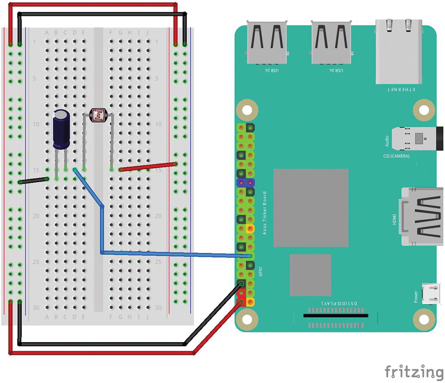
The photocell resistor and capacitor circuit. Notice the polarity of the capacitor, as well as the shared rail between the capacitor and the photocell.
readPin will be our variable for the data being sent to the terminal, and the delay will affect how fast the data is read. You’ll notice it’s set to come in very quickly, so if you need a slower reading, feel free to increase the delay.
Make sure to save your new program as photocell.py in the test folder that we’ve been using and then open a terminal window.
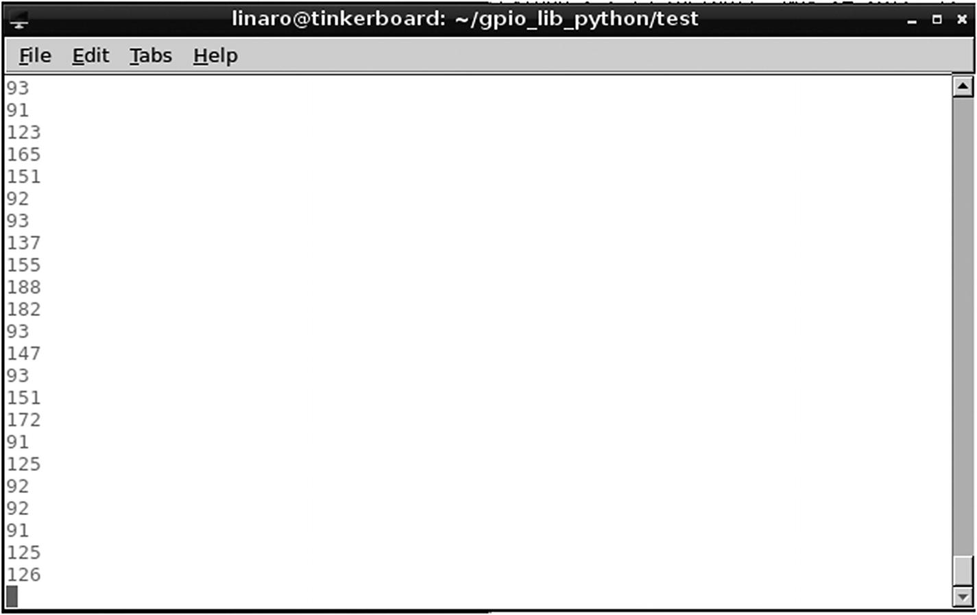
The data sent to the terminal when the photocell resistor is exposed to a large amount of light
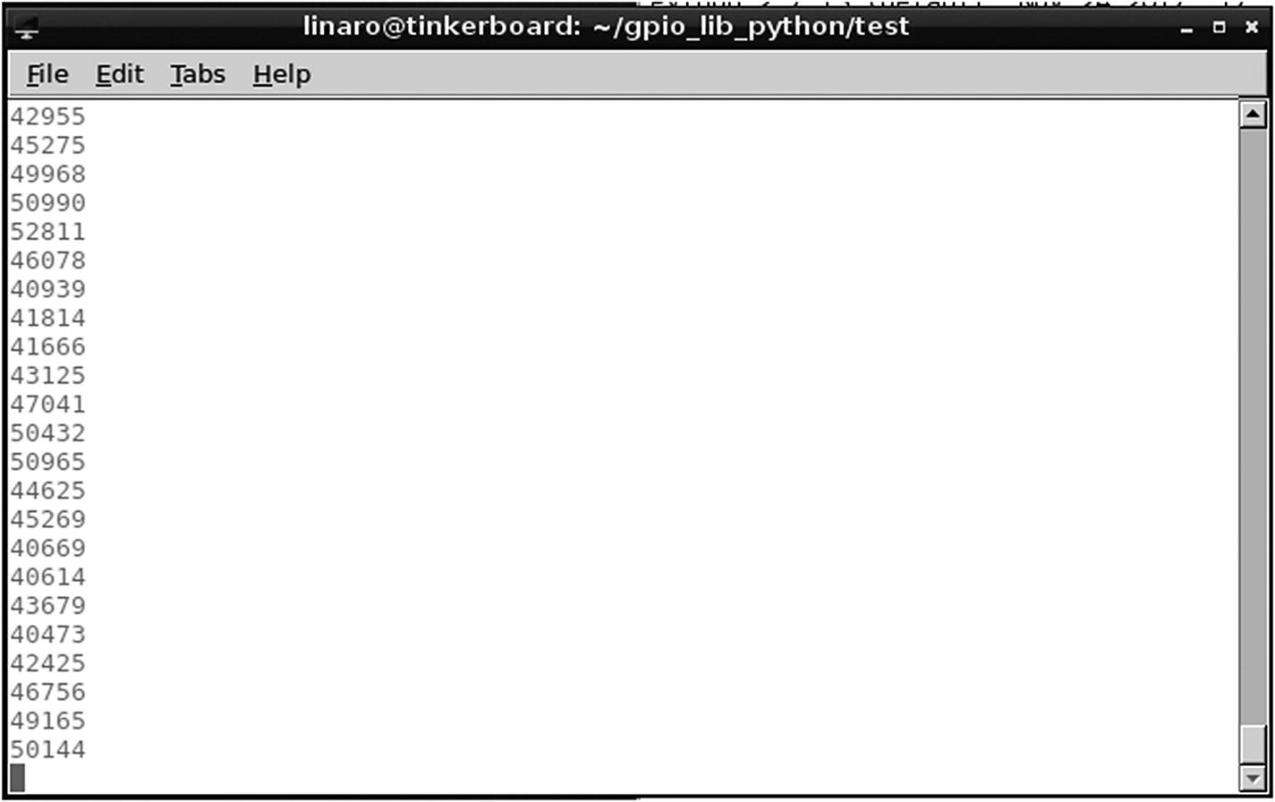
The data sent to the terminal when the photocell resistor is exposed to little or no light
Although they are basic in principal and composition, these circuits and corresponding programs should give you the beginning tools to form your understanding of the Tinker Board’s GPIO pins and the use of the GPIO pin library for Python.
Installing the C Library
You’ll see the library go through the download and installation process.
Unlike the Python library, the C library does not download as a zipped file. Instead, it comes as a folder that needs to be decompiled using the build command in the terminal, which will execute a build file within the folder we just downloaded, like the way we ran the setup.py program to finish setting up the Python library.
First, we’re going to change directories to our new C library folder by entering cd /home/linaro/gpio_lib_c into the terminal. You should see the new file extension on the left side of the terminal after this. If you look at the file directory GUI in the folder at the same time, you’ll see the build file in question. Before we can execute it, we need to make it an executable file by using the change mode command that we looked at earlier with Python. Enter chmod a+x build into the terminal followed by sudo ./build to execute the file. After this, the C library is fully set up.
The C GPIO library is heavily dependent on a port of the wiringPi library, which was written for use with the Raspberry Pi family of boards. As a result, the included examples may even reference Pi boards rather than the Tinker Board. A benefit of this is that there are more code examples available than there are for the Python GPIO library, including an example of Blink in C. Let’s look at this file using the Geany IDE, which we installed in the previous chapter .
Blink in C
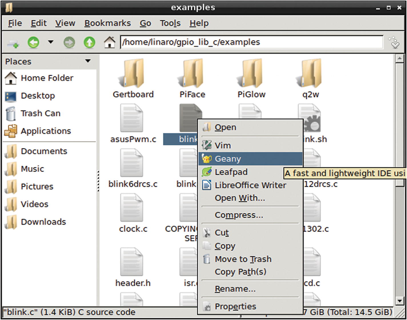
Opening the blink.c example code that comes with the installation of the GPIO library for C. We’re opening it with Geany so that we can edit, compile, and run it.

Blink.c opened in Geany
In looking at the code structure, the first thing that stands out is that as we did with Python, we’re including libraries at the start of the script. The first is <stdio.h>, which is the input and output library that is standard to the C and C++ languages. The second library is <wiringPi.h>, which allows for communication between C and the GPIO pins and as previously mentioned is ported from the Raspberry Pi boards. And speaking of the GPIO pins, the first line of code after the library imports is the definition of the LED GPIO pin as pin 0. Of course, we aren’t counting the physical GPIO pins in binary, so which pin is pin 0?
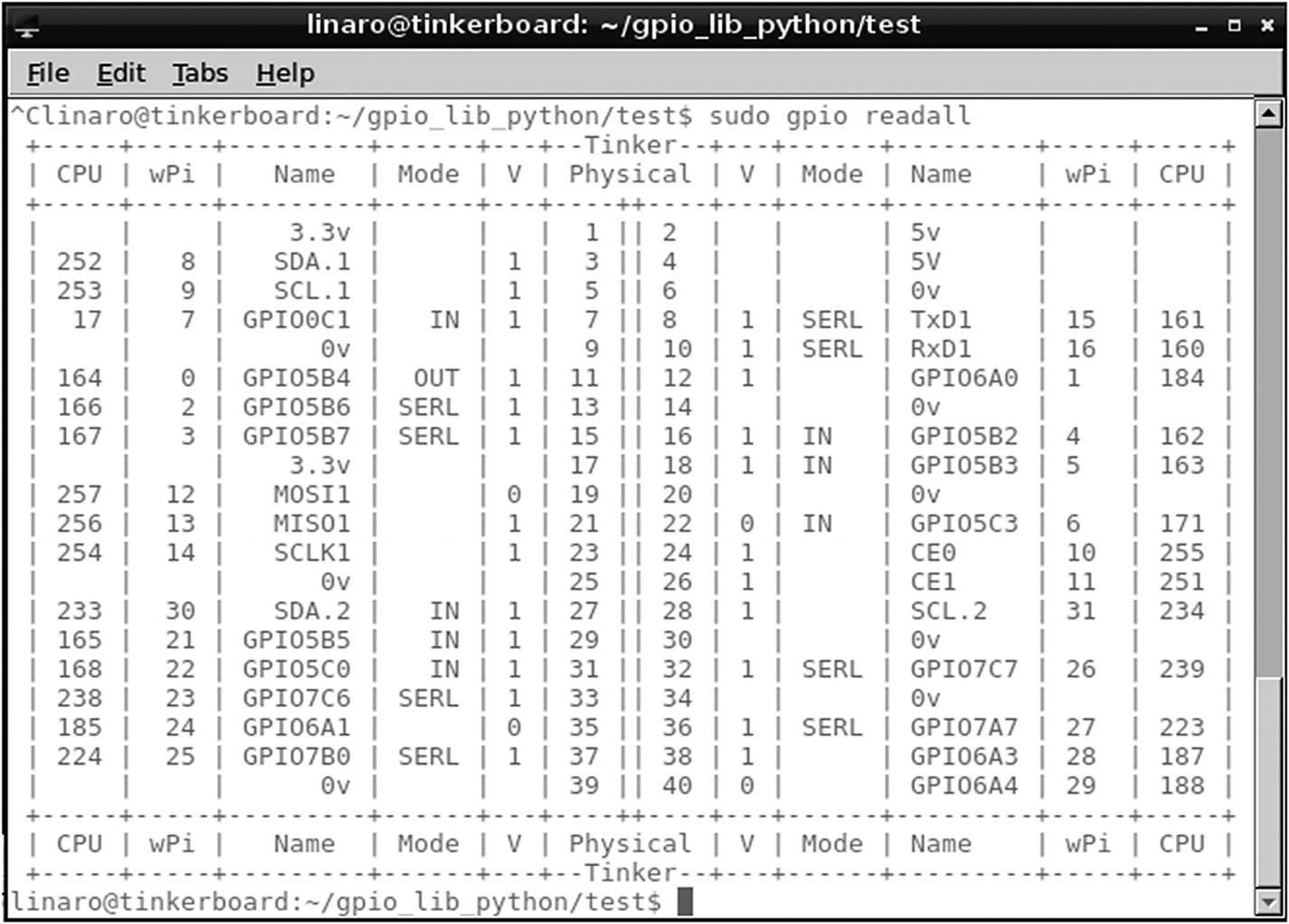
The GPIO numbering sequences as seen after entering sudo gpio readall into the terminal
Looking at the chart, we can see that wiringPi pin 0 is the equivalent to physical pin 11, so if you still have your breadboard assembled from earlier, you won’t have to change any of your wiring for the LED circuit. It can remain in the same state shown in Figure 5-4 earlier.
Edit that line and then save it. Now we can compile the code and run it. Since we’re using Geany, we can do everything from within its window, including tasks that would have required a separate terminal window; if you look at the bottom of the Geany window you can see that there is a Terminal option, as shown previously in Figure 5-14.
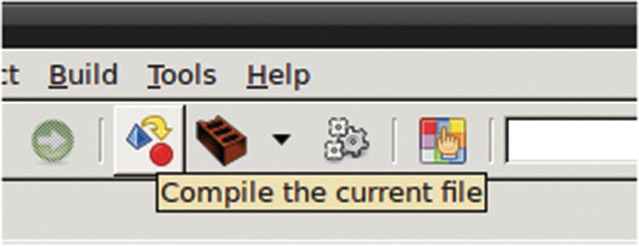
The GUI button to compile in Geany
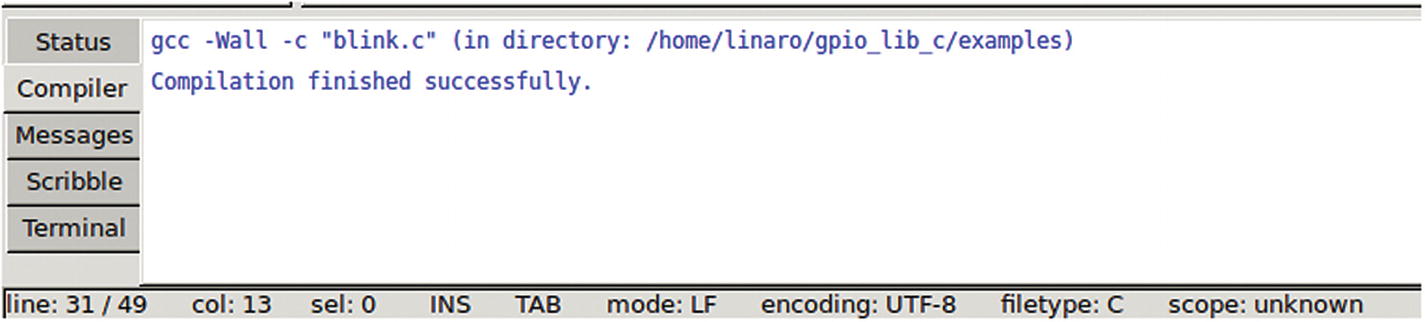
The message after a successful code compilation
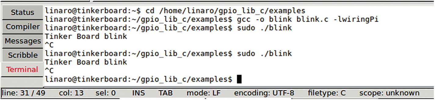
Blink.c running via the terminal in Geany
Button in C
Much like the way we progressed with Python, let’s add a button to our LED circuit and code in C. We’re going to set up the same circuit that we did previously, connecting one lead from the button to the ground rail and the other lead to GPIO pin 13 as shown in Figure 5-8.
For the code, rather than editing the Blink example sketch we’re going to start from scratch to get a better feel for how the C programming language works and the dependencies that are necessary to write programs for the Tinker Board’s GPIO pins. Example code is great since you can run it without worry, but you really aren’t learning anything by just executing pre-written scripts.
Now we’re ready for the loop. We’ll need to include the wiringPi setup call to initialize the library and then set the LED as an output and the BUTTON as an input, since the LED is receiving data from the Tinker Board and the button is sending data into it. Then we’ll begin the loop with a while statement.
Note
Notice the syntax differences between C and Python. In the same way that indentations and colons are important in Python, curly brackets, semicolons and parenthesis are very important in C. Always check to make sure that you have closed sets of curly brackets and have semicolons placed appropriately at the ends of lines. Indentations in C are not related to syntax but are used to keep the code neat and readable.
Now save your program in the examples folder of gpio_lib_c as button.c and follow the steps outlined earlier to compile, build, and execute your new script to control an LED with a button. Just as before, you can also substitute a switch for a button for a more permanent lighting solution following the circuit diagram shown earlier in Figure 5-9 .
Note
If you do not include “.c” at the end of your program name when saving, Geany will not recognize it as a program written in C, and as a result you will not be able to compile.
Pulse Width Modulation
A common hardware programming concept that we have not discussed yet is Pulse Width Modulation (PWM), which enables you to control components in a way that resembles analog control. It’s similar to what we explored with the photocell resistor, but using digital controls rather than a hardware workaround.
As we’ve discussed, the GPIO pins utilizing digital methods can be either on or off. PWM takes advantage of this by sending an on signal for a certain portion of time to the pin and then turning the pin off for a certain portion of time so that it pulses continuously in this pattern. The amount of time that the pin is on is referred to as the pulse width , and different patterns are referred to as duty cycles, described in percentages. For example, a 100% duty cycle would have the pin on for 100% of a measured time period, and a 25% duty cycle would have the pin on for 25% of a measured time period.
There are two types of PWM: hardware-controlled PWM and software-controlled PWM. The difference between the two is that hardware-controlled PWM has the duty cycle and bit toggling (on or off signal) controlled via the hardware on the board, while software-controlled PWM has everything controlled via the software. On the Tinker Board there are three pins that allow for hardware-controlled PWM: physical GPIO pins 32 and 33 and a third standalone PWM pin located between the USB ports and the Ethernet port. To use that third pin, you will have to solder directly to the Tinker Board, since it does not come with a header included.
To use PWM on any of the other GPIO pins, you will have to use software-controlled PWM. There is a library included in wiringPi for software-controlled PWM, though, so it can be done. First, let’s look at how hardware-controlled PWM is implemented in C on the Tinker Board.
Coding with Hardware-Controlled PWM
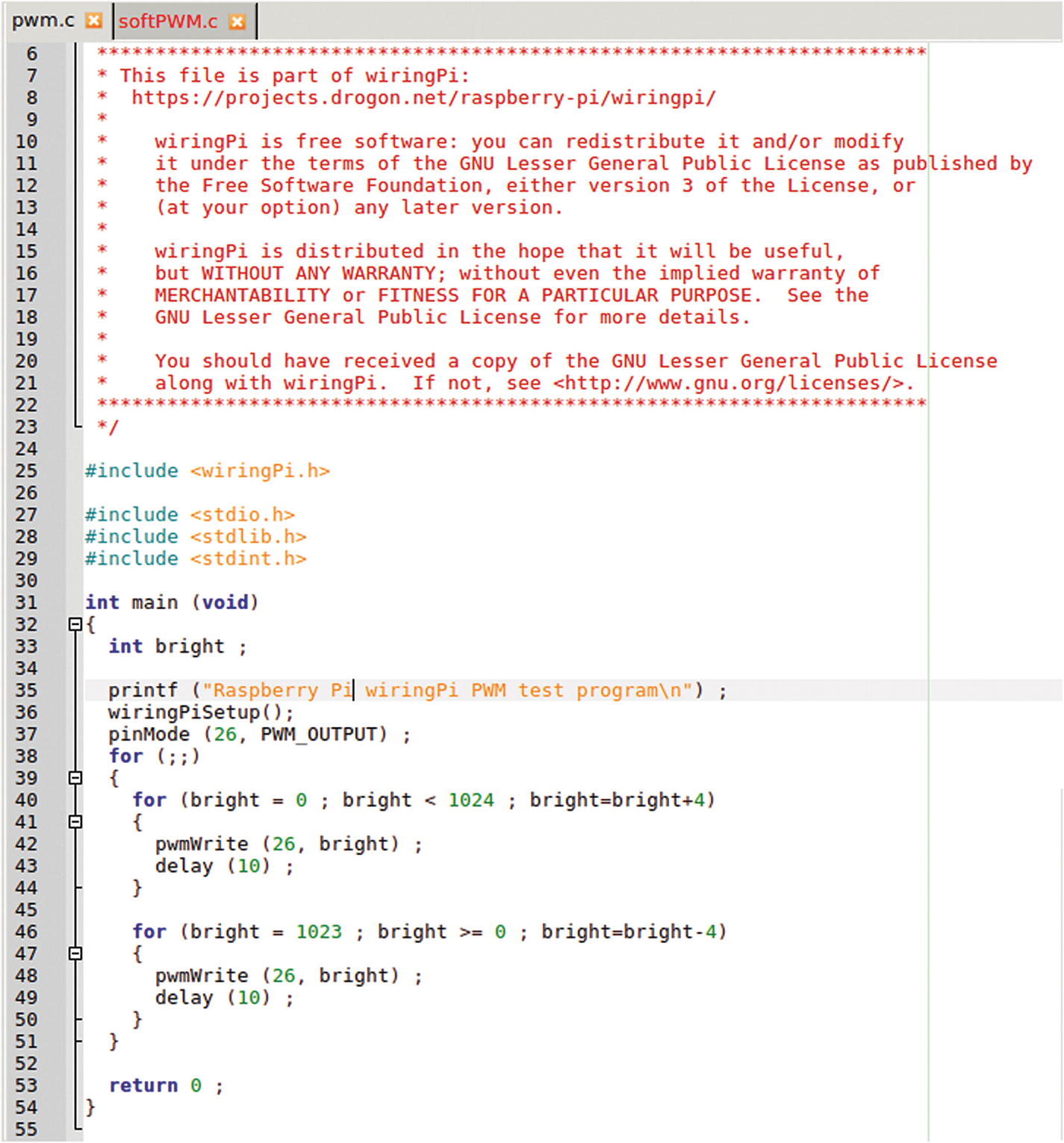
The included hardware PWM example code entitled pwm.c
There are two more libraries included at the top that we haven’t seen yet in C; <stdlib.h> and <stdint.h>. Both are C libraries; <stdlib.h> is a general utilities library, and <stdint.h> is an integers library. Both are needed for the increased software needs for PWM.
The loop is set up with the integer bright acting as a placeholder for the pulse width value. There are two for loops inside the main loop. The first increases the pulse width incrementally, which will have the LED steadily increase in brightness until it reaches the maximum brightness possible. The second decreases the pulse width incrementally, which will make the LED steadily fade until it is completely off. The value of 1024 expressed in the for loops is the maximum analog value in the C programming language, which is used since PWM is imitating analog behavior.
The final important note about this program is the pin that the LED is attached to. Since this is a hardware-controlled PWM example, we’ll need to attach the LED to one of the hardware PWM GPIO pins. The pin used in the example is wiringPi pin 26, which corresponds to physical pin 32 as seen previously in Figure 5-15, by referencing gpio readall in the terminal.

The circuit diagram for attaching the LED to GPIO physical pin 32 for hardware-controlled PWM

The hardware-controlled PWM test code running via the terminal in Geany
Coding with Software-Controlled PWM
The first three libraries are the general C libraries that we’ve been working with, followed by the wiringPi library and then a new library to us: <softPwm.h>, which is the software PWM library for use with wiringPi. This will allow us to use some special software PWM functions in our code to streamline our program.
LED is going to symbolize the GPIO pin that our LED is attached to. Again, you can use any GPIO pin for software PWM, but let’s stick with GPIO physical pin 11, which is wiringPi’s pin 0, since we’ve been using it throughout this chapter. The variable int i is going to act as the place holder for the pulse width value, much as bright did in the hardware PWM example that we just looked at.
The softPwmCreate command takes three arguments; the first is the pin that will be set up for software PWM. Next is the minimum pulse width value that will be received via the software. Here we have that as 0, or off. Finally, the third parameter is the maximum pulse width value that will be received. 100 is best practice for use with the library. Unlike the hardware PWM example that utilized the true analog maximum value of 1024, the wiringPi software PWM works best with a maximum value of 100, since it is completely digital dependent.
Return the LED’s positive lead to GPIO physical pin 11, as previously shown in Figure 5-4, and then compile and execute the softPWM.c program. As in the hardware PWM example, your LED should be smoothly fading on and off continuously.
Note
Both hardware and software PWM are available in the Python library as well.
The Lack of a Real Time Clock
Now that we’ve gone over some basic hardware programming with the GPIO pins, you may be thinking that using a single-board computer for your hardware project needs is the best way to go. At first glance, the benefits in doing this are overwhelmingly positive. You can use multiple programming languages, the board is running a full version of Linux, and the SoC’s CPU is much more powerful than most microcontroller boards, such as an Arduino. But despite these advantages, there is one very important feature that SBCs running Linux lack that almost all microcontroller boards have: a real time clock.
A real time clock is very important for programming hardware components. It allows everything to work as expected and to run smoothly; especially with things like PWM which could be controlling motors or other components whose proper operation depends on receiving the correct timing instructions.
When programming hardware on an SBC running Linux, we control the clock purely through software. This works, as you’ve just seen with all the examples, but it will never be as dependable in the long term as a microcontroller or in situations that require precise timings, such as motor control. This also eats up CPU resources with the SoC. In fact, for every pin that you run software PWM on the Tinker Board you’ll notice a CPU usage increase between 10 and 20%. With all this in mind, when should you use the GPIO pins on the Tinker Board or other SBCs?
As discussed at the very beginning of this book, it’s the features of a full desktop operating system, Internet connectivity, processing power, and much more that make SBCs so useful. The GPIO pins are a bonus to these main features and as a result are not the focus of what these boards can offer. They should be used to compliment a project or when using a traditional microcontroller board will be more cumbersome.
Examples include when a specialized operating system that focuses on a specific task, such as game emulation or file management, will be in use and requires a few shortcut buttons to easily navigate rather than keeping a keyboard hooked up. Or when sensors will be reading data that will be logged and require storage to eventually be published on a social media page. These are just a few projects that could see the benefit of an SBC with GPIO pins.
You can see why if you just wanted to blink a few LEDs you will probably be better off using a microcontroller rather than an SBC. We’ll be going over a few project options in the third part of this book that will further demonstrate when an SBC, and specifically the Tinker Board, is the best choice for a project.
Wrapping Things Up
In this chapter we were able to gain an understanding of how the GPIO pins on the Tinker Board work with both the Python and C libraries. We also discussed the best use case scenarios for implementing the GPIO pins in a project on an SBC such as the Tinker Board. We’ll be building on this basic knowledge during the projects portion of this book. But first, there is one additional operating system from ASUS for the Tinker Board to explore: Android!