
APPENDIX H
Single-Tone Intermodulation Distortion Suppression for Double-Balanced Mixers
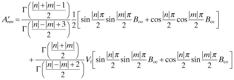
An expression is given in [1] for the suppression for single-tone intermodulation distortion in a double-balanced mixer. This is repeated below as well as coded in the program IMSUP. The intermodulation suppression in dBc (dB below the carrier) is Snm for a set of frequencies nfp ± mf1:
(H.1)
![]()
The difference in dB between the RF signal and LO power is ΔP.
(H.3)
![]()
![]()
![]()
![]()
![]()
![]()
The value for Vf in Eq. (H.2) is the ratio of the forward saturation diode voltage, Vsat and the peak LO voltage, VL. Thus,
(H.4)
![]()
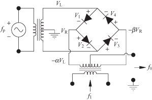
The α and β represent the isolation in the LO and RF transformers resulting from their imbalance. The imbalance is illustrated in Fig. H.1, which is the same as used in Fig. 11.5 except the diode numbering convention has been made here to conform to that used in [1]:
![]()
![]()
FIGURE H.1 Double-balanced mixer with transformer and diode imbalanced.
The values for δ are a measure of the inequality of the forward voltages across the diodes:
![]()
![]()
![]()
Under ideal conditions
![]()
Typical values for isolation by the transformers are 10 to 15 dB while the values for δ range from 0.85 to 1.15.
The equations have been implemented in a program called IMPSUP, which determines the single-tone intermodulation suppression for a given set of frequency harmonics of the RF signal and LO oscillator, the relative RF signal and LO power levels, the peak value of the LO voltage, imbalances resulting in finite isolation in the transformers, and imbalances in the diode forward voltage drops. A sample run of IMSUP shows the intermodulation suppression for a variety of frequency harmonics.
LO and RF Signal Transformer Isolation (typ. 10 to 15 dB)
10.,10.
Ring diode voltage ratios: V2/V1, V3/V1, V4/V1 = ?
Typically .85 to 1.15 (ideally =1)
0.85, 0.90, 1.15
Difference in LO and RF power in dB (typ. −20.)
−20.
Peak LO voltage = ?
3.
Forward diode saturation voltage (typ. 0.1)
IM product n x FL +− m x Frf: n,m = ?
1, 1
For intermodulation product n x m = 1 1
IM Suppression = 0.000000E+00 dBc
New n,m values only? <Y/N>
y
IM product n x FL +- m x Frf: n,m = ?
2, 1
For intermodulation product n x m = 2 1
IM Suppression = -0.437641E+02 dBc
New n,m values only? <Y/N>
y
IM product n x FL +- m x Frf: n,m = ?
3, 1
For intermodulation product n x m = 3 1
IM Suppression = -0.954243E+01 dBc
New n,m values only? <Y/N>
y
IM product n x FL +- m x Frf: n,m = ?
3, 2
For intermodulation product n x m = 3 2
IM Suppression = -0.602423E+02 dBc
New n,m values only? <Y/N>
n
Completely new mixer specs? <Y/N>
n
fin
REFERENCE
1. B. C. Henderson, “Reliably Predict Mixer IM Suppression,” Microwaves RF, 22, pp. 63–66, 68–70, 132, Nov. 1983. Also reprinted in RF and Microwave Designer’s Handbook, Watkins-Johnson 97–98 Catalog.