
3
HOT GLUE NIGHT-LIGHT
IN THIS PROJECT, YOU’LL CREATE A TINY, CUSTOMIZED LIGHT BY USING A HOT GLUE GUN, A SILICONE ICE CUBE OR BAKING MOLD, AND AN LED. THEN YOU’LL WRITE A PROGRAM TO MAKE THE LIGHT FLASH ON AND OFF OR FADE IN AND OUT. YOU’LL TAKE THIS PROJECT FURTHER BY ADDING A LIGHT SENSOR TO MAKE A NIGHT-LIGHT THAT TURNS ON AUTOMATICALLY IN THE DARK AND TURNS OFF AS THE SUN COMES UP.
Hot glue is a type of plastic adhesive that’s runny when hot, so it’s ideal for filling up any shape and drying quickly into that shape. Silicone molds are heat resistant, which prevents the glue from sticking to the mold, making it easy to pop out the glue when it’s set. Figure 3-1 shows a completed light.

FIGURE 3-1 R2-D2 glue gun light
WHAT YOU’LL NEED
Here are the items you’ll need for this project:
- Raspberry Pi
- Glue gun
- Glue sticks
- Silicone mold
- LEDs
- Female-to-female wires
- Breadboard
- Photoresistor (LDR)
- Resistor (between 220 and 330 ohms)
- 0.1 uF capacitor
Choose any shape of mold that suits your fancy! Recently, I made a green R2-D2 LED and a red Death Star. I also located some Avengers molds, so I created a green Hulk fist that pulses, a blue Captain America shield, and a red Iron Man face.
Just make sure the mold is silicone so it’s heat resistant. In addition, you should know that photoresistors are also called light-dependent resistors (LDRs) or photocells.
WARNING
The glue gun will get very hot. Never touch the end of the gun or the glue until it has cooled down. Also, be wary of dripping glue: don’t get it on your shoes, clothes, or the floor. Consider putting newspaper down on your build surface first to protect it.
BUILDING THE CUSTOM NIGHT-LIGHT
The custom night-light build has two stages. First, you’ll physically make the light. Second, you’ll code a program to give the light its instructions. Let’s get started.
Follow these steps to construct the light:
- Prepare the glue gun: Slide a glue stick into the glue gun, plug it in, and let it heat up for a few minutes. A small amount of glue will usually drip from the end when it’s ready to use.
- Prepare the mold: Place your silicone mold onto a stable surface. You might want to place some paper or a dust cover underneath the mold to protect the surface. Ensure that the mold is dust free and dry.
- Prepare the LED: Pick up the LED and look at the two wires, also called legs. Notice that one is slightly longer than the other, as shown in Figure 3-2. The longer leg is the positive leg; the shorter leg is negative. This detail is important to remember when you’re attaching the LED to the molded figure. If you wire the legs the wrong way, the circuit won’t close and current won’t flow through the LED, meaning the LED won’t light up.

FIGURE 3-2 LED legs
Because you need to access the legs when the glue is set, check where you want the LED to sit in the mold before you add the hot glue. Do you want the legs to stick straight out, or maybe bend downward or outward? Your placement of the LED will depend on your mold’s shape. You want your LED, including the legs, approximately halfway into the mold. Too far in, and the LED will stick out; not in far enough, and it won’t remain securely in the glue. Roughly estimate where to place the LED.
- Add the resistor: Wrap one end of the resistor around the LED’s longer positive leg. The resistor prevents the LED from overheating and burning out.
- Add glue to the mold: When you know where you want to place your LED, take it out of the mold. Then, using the preheated glue gun, begin to slowly squeeze the glue into the mold. When the mold is about 80 percent full, gently push the LED into the glue, holding it by the legs. Once the glue has settled, you might need to add a little more glue until the mold is full. Hold on to the LED, but don’t get hot glue on your fingers. Figure 3-3 shows a good position for the LED.
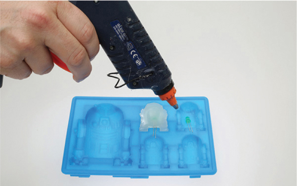
FIGURE 3-3 Filling the mold with hot glue
- Position and hold the LED: When the mold is full, put the glue gun down. Continue to hold the LED so it’s positioned exactly where you want it while the glue dries.
After a few minutes, the glue will begin to turn a whitish color. At this point, you can let go of the LED and let the glue set for about 15 minutes. Then gently touch the glue. If it’s no longer sticky, carefully peel the mold away from the glue. If the glue figure doesn’t come out easily, you might need to leave it alone for a few more minutes so it can completely set.
- Wire up the LED: When the glue has totally set and cooled down, take two female-to-female jumper wires and attach one to each of the LED’s legs. The positive leg has the resistor wrapped around it, so attach the wire to the end of the resistor. Attach the wire from the positive, longer leg to GPIO pin 18, which is physical pin number 12 on the Pi. Connect the shorter, negative leg to any one of the ground pins on the Pi: you can choose from physical number 9, 14, 20, 30, 34, or 39. Figure 3-4 shows the wiring for hooking up the LED, the positive leg is the straight leg.

FIGURE 3-4 Wiring diagram for the LED
Coding the Night-Light
Now it’s time to add the software. Here are the steps:
- Plug in and boot up your Raspberry Pi.
- Load Python either by opening the terminal and entering sudo idle3 or by clicking the Pi icon and selecting Start ▶ Programming ▶ Python 3.
- From the IDLE window, select File ▶ New File, as shown in Figure 3-5.

FIGURE 3-5 Opening a new file in IDLE
- Enter the simple code in Listing 3-1 to make the LED flash on and off.
   from gpiozero import LED
   from time import sleep
❶ led = LED(18)
❷ while True:
    ❸ led.on()
    ❹ sleep(1)
       led.off()
       sleep(1)
LISTING 3-1 Flashing the LED
Let’s look at how this code works. First, you import the LED class from the gpiozero library, which contains commands to help you control the LED. You also import the sleep() function. A function consists of code that performs a particular task but is represented by a single word (or two) that acts as the function name. When you call that function name in your code, Python runs the instructions in the function, sparing you from having to enter all those lines again. You can name the function whatever you desire, although it’s best to use a word that describes what the function does. For example, in the previous chapter, when we used the code print ("hello"), the word print is a function. The IDLE editor colors all function names light purple, making them easy to identify. The print() function contains several code lines that display in the IDLE window the text inside the parentheses. You’ll use the print() function a lot in many of the chapters.
The sleep() function adds a delay between instructions. This means you can flash the LED on and off at different speeds. If you use a lower delay value, the LED flashes faster. Then you tell the Pi which pin the LED is connected to, which is pin 18 ❶.
You create a loop that repeats the instructions indented below it forever unless you stop the program ❷. Finally, you add the instructions to the loop: turn the LED on ❸, wait for 1 second ❹, turn the LED off, and wait for 1 second. The LED will flash forever.
Running Your Program
To run the program and make the LED flash, press F5 on your keyboard. You should be prompted to save the file. Name and save your program: your LED mold should then come to life! To end the program, close the Python window by clicking the X.
Modify: Fading the LED
You can modify your program so the LED fades in and out, also known as pulsing, instead of flashing on and off. Open a new Python file and add the code in Listing 3-2. This program gradually makes the LED brighter, and then it fades out.
from gpiozero import PWMLED
from signal import pause
led = PWMLED(18)
led.pulse()
pause()
LISTING 3-2 Fading the LED
Here you import the PWMLED class to enable you to pulse the LED, set the GPIO pin number you’re using for the LED, and then set the pulse. You also add a pause, which ensures that the program continuously runs and reduces the load on the CPU, making it run faster. Normally, the program runs once and then the GPIO pins are reset. The pause() instruction ensures that the signal to the GPIO program is not stopped: the program continues to run so the LED flashes until you exit the program.
Save this code and run it to see the difference!
BUILDING THE LED NIGHT-LIGHT
Let’s level up the night-light project. You’ll add a photoresistor to make a simple night-light to add atmosphere to your room, as shown in Figure 3-6. A photoresistor is a sensor that measures the amount of light in the room and returns a value. This value can trigger the light to turn on or off, depending on how dark it is.
Light readings are analog, which means they can be any value, not just on or off. Think of the sun rising or setting: it doesn’t just appear in the morning; instead, the light gradually increases. Computers, on the other hand, are digital, meaning they understand only on or off values. Computers use millions of tiny switches that can be turned on or off (like a light switch).
However, if you have a dimmer switch, you can adjust the light to different levels of brightness. You’ll use a similar technique here.
When light hits the photoresistor, it creates a small electrical charge. You’ll store this charge in a capacitor, which is a small device designed to store electrical charge. You can then use the amount of charge stored in the capacitor to indicate how much light was detected.
If the capacitor is fully charged, the reading will be a value of 1, meaning the room is fully lit and you don’t need the night-light on. A reading of 0.4 means that the room is lit about 40 percent and that it’s dark enough for your Pi to turn on the light.

FIGURE 3-6 An Ironman night-light
Wiring Your Night-Light
You need to keep your LED light attached to GPIO pin 18. Figure 3-7 shows the wiring diagram for reference.
Follow these steps to wire the light:
- Add the new parts: Place the legs of the photoresistor into your breadboard, leaving at least one line of space between the legs. Add the capacitor to the breadboard, with one of the legs in the same row as the right leg of the photoresistor, as shown in Figure 3-7.

FIGURE 3-7 Adding the capacitor and the photoresistor to the breadboard
- Add the wires: Add wire 1 in line with the left leg of the photoresistor. Add wire 2 in line with the right leg of the photoresistor and the left leg of the capacitor. Place wire 3 in line with the left leg of the capacitor. These wires are shown in Figure 3-7.
- Connect to your Raspberry Pi: Connect wire 1 to the first physical pin, the 3V3 pin, which provides the power. Connect wire 2 to GPIO pin 4: this is the fourth physical pin on the left. Connect wire 3 to the ground pin, GND. I recommend you use the nearest ground pin, number 6.
Coding the Night-Light
To code the night-light, start a new Python file and then add the program in Listing 3-3.
❶ from gpiozero import LightSensor, LED
❷ import time
❸ ldr = LightSensor(4)
❹ led = LED(18)
❺ while True:
       print (ldr.value)
       time.sleep(2)
    ❻  if ldr.value <= 0.4:
           print ("light on")
           led.on()
    ❼ else:
           led.off()
LISTING 3-3 Coding the night-light
You import the LightSensor and LED classes from the gpiozero library to help you control the photoresistor and LED, respectively ❶. Then you import the time module so you can add a short pause between each light reading ❷. To begin with, you’ll set the value to 2. This will enable you to test the program by placing your hand over the photoresistor. When you use the program as a night-light, you can increase the time delay. Because a sunset can take several minutes, taking a reading every second would be pointless; reaching the required light level could take 45 minutes, and your Pi would have to take more than 2700 readings, using up processing time and power.
At ❸ you tell the program that the photoresistor is attached to GPIO 4. Then you tell the program that the LED is attached to GPIO pin 18 ❹.
You create a while True loop to make the program continuously take light readings and check the value so it doesn’t miss the sunset ❺.You print the light reading value to the screen and add a short pause of 2 seconds. You might be interested in the light value readings, and seeing them onscreen will make it easier for you to test if the program is working correctly.
You then use a conditional to check whether the light reading is less than or equal to the value 0.4 (remember that 0 is no light and 1 is full sunlight) ❻. A conditional is an instruction that tells the program to run certain commands only if something is true. This if statement tells the program that if the value is less than or equal to 0.4, it’s getting dark, so the program should print an optional warning message and turn on the night-light. You can adjust the light level to match your environment. For example, if you live in a city, you might need to set the value higher to account for streetlights.
The else statement is another conditional that tells the computer that if the reading is above 0.4, it should turn off the LED ❼.
Running Your Program
To run the program and test your photoresistor, press F5 on your keyboard. This will prompt you to save your file with a recognizable name, and then it will run. Test your night-light by placing a cloth or your fingers over the sensor to block the light: this should trigger your night-light to turn on.
You can adjust the sensitivity by reducing or increasing the value on line 8 of the program. For example, try changing the line to the following:
if ldr.value <= 0.2:
This line will trigger the light only when it’s very dark. To end the program, close the Python window by clicking the X.
The light in your room and the type of LED you’re using will determine the best values for you to use. Experiment with photoresistor values to find the one most appropriate for your environment.
WRAPPING UP
You now have a working, custom-built night-light. Here are a few ideas for improving your light:
- Create more LED creatures and add them to your collection.
- Use different-colored LEDs to make different-colored lights.
- Add glitter to the glue before the glue sets to make it sparkle.
- Use a small coin-style battery to make the feature portable by placing the battery between the LED legs.
- Reverse the light value so the LED light is an alarm and flashes when the light value is above 0.80.