
12 Consistency Management of UML Models
Emilia Farcas, Ingolf H. Krüger and Massimiliano Menarini
CONTENTS
12.1.1 Multiview Models and Consistency Challenges
12.2 State of the Art in Consistency and Semantics
12.2.1 UML Model Consistency Requirements
12.3.1 Queries and Constraints Semantics
12.3.1.1 Notational Preliminaries and System Formalization
12.3.1.2 Abstract Specification Language
12.3.1.3 Specification Language Semantics
12.1 Introduction
Model-based engineering (MBE) [1] approaches support the use of models throughout the development process from requirements elicitation, to architecture specification, to system analysis, and deployment. Models can be leveraged in a variety of ways. During requirements elicitation, models help in defining the problem domain and communicating with stakeholders. During development, models can be used to define clear interfaces between components developed by separate suppliers. Modeling can also provide support for system synthesis by using model transformations and automatic code generation. For analysis, models can be used to verify system properties before the system is actually deployed. Moreover, models can also be used at runtime to monitor the system behavior and identify compliance to behavior interfaces and QoS properties.
Notably, modeling languages are most useful when they fulfill some key requirements. Two important requirements for modeling real-time embedded systems are a clear definition of the semantics of models together with the ability to guarantee that models are consistent. In fact, without a consistent set of models and a precise and complete semantics it is impossible to leverage models to synthesize code or to verify properties of the modeled system, which are two important activities in MBE of embedded systems. It is worth noting that consistency and semantics are two closely related aspects of a language. In fact, without a formal semantics it is impossible to prove the absence of inconsistencies.
The OMG’s Unified Modeling LanguageTM (UML®) [2,3] is a general-purpose modeling language widely used across application domains. It is a family of graphical notations underpinned by a single metamodel [4]. It provides 14 types of diagrams, which support modeling structural (i.e., static) and behavioral (i.e., dynamic) views of a system. The UML provides a built-in extension mechanism through profiles, which allows tailoring the UML for a particular domain or target platform. The recent UML profile for Modeling and Analysis of Real-Time and Embedded Systems (MARTE) [5] allows specifying timing properties, supports component-based architectures and different computational paradigms, allows for modeling of both software and hardware platforms along with their nonfunctional properties, and supports schedulability and performance analysis.
In Chapter 5, we presented the modeling capabilities of UML and MARTE and discussed how ensuring consistency and defining a formal semantics is still an open issue in UML. In this chapter, we discuss various approaches to model consistency and we present an innovative solution. We picked the topic of model consistency to explore in detail because we believe it is paramount for a comprehensive modeling methodology.
In the following paragraphs, we discuss the consistency problem in UML and give an example of inconsistent models.
12.1.1 Multiview Models and Consistency Challenges
To tackle complexity, MBE approaches support multiple perspectives with associated modeling languages, each focusing on a particular subset of system properties. Each perspective can cover a separate aspect of the same part of the system or depict the same aspect with different notations to clarify or stress a modeling concept. For instance, we could use a sequence diagram to show the communication protocol between two class instances and two state-machine diagrams to describe the proper ordering of the method calls upon each class. These two perspectives clearly overlap. This overlapping requires that all models are consistent.
The UML standard from the Object Management Group® (OMG®) comprises many languages (14 types of diagrams), each emphasizing a different structural or behavioral modeling aspect. The most recent version is UML 2.3, whose specification consists of the UML Superstructure [3] defining the notation and semantics for diagrams and the UML Infrastructure [2] defining the language on which the Superstructure is based. Constraints can be expressed in the textual Object Constraint Language [6].
When using multiple modeling perspectives, the central question from an engineering point of view is this: Is the modeled system realizable? However, UML does not provide a complete formal semantics, which leaves issues such as model consistency unsolved.
In this chapter, we will focus on the issues related to consistency of UML models. We discuss the UML consistency problem in detail, explain how it originates or is worsened by the trade-offs in the language design, and propose an avenue to solve it. We chose this problem for its importance not only in the real-time systems domain but also in most areas where MBE is applied. One important example is the field of feature modeling. In this field, different software functionalities (features) are modeled separately and programs are generated by composing features. A recent article [7] argues that model consistency is still an open and important issue in this area.
Furthermore, Model-Driven Architecture® (MDA®) [8] is an MBE approach that distinguishes between a platform-independent model (PIM) and a platform-specific model (PSM). PIM captures the core system entities and their interactions without specifying how these are implemented. PIM can be mapped to multiple PSMs, each capturing all aspects of a particular deployment architecture. UML is the language choice of MDA, where both PIM and PSM are expressed as UML models. The distinction between PIM and PSM also introduces a requirement for model consistency.
The first issue to solve when discussing model consistency for UML is to clearly define what kind of consistency we are interested in and how to effectively determine whether or not a UML model is consistent. Of course, UML is a broad-spectrum language with an informally defined semantics, which serves the goal to be inclusive with respect to modeling styles and domains. However, this creates the first hurdle we have to overcome in our consistency definition. Any approach aiming at defining consistency needs to explicitly or implicitly define a more precise semantics for UML. A rich body of work exists in the literature on defining multiview or multiperspective consistency based on UML semantics definitions. In Section 12.2, we will examine this related work.
Although the consistency problem has been extensively studied in the literature, a solution has been elusive—especially in the context of the UML with its rich set of interrelated description techniques for system structure and behavior. Existing approaches to defining UML model consistency lead to complex definitions of the notion of consistency or address only a subset of the available modeling notations. Our goal is to create a consistency checking approach that is flexible enough to be able to target the full UML language. However, we do not want the engineer to be forced to fully define the semantics of all UML notations, only the semantics of a subset (profile) of the UML language used in the specification should be defined.
The main novelty of the consistency checking approach we present in this chapter is in the comprehensive, yet simple mechanism we introduce for specifying consistency rules. Instead of analyzing the semantics of the UML at the metamodel level and extracting consistency rules between different diagram types, we define a simple execution framework (similar to a “virtual machine”), based on a target ontology whose concepts map one-to-one to elements of the system class we are interested in modeling, i.e., distributed, reactive systems. All UML diagram types are then treated as model generators for this virtual machine; each diagram selects entities of the virtual machine and constrains their structure or behavior. Model consistency is then simply defined as the presence of virtual machine behaviors under the specified constraints.
12.1.2 Inconsistency Example
We revisit the example from the Bay Area Rapid Transit (BART) [9] system, introduced in Chapter 5, Sections 5.3.2.3 and 5.4.2.3. BART is the commuter rail train system in the San Francisco Bay area. The BART system automatically controls over 50 trains on a large track network with several different lines. We show three modeling perspectives of BART using UML 2.3 and the MARTE profile: component, sequence, and state-machine diagrams (see Figure 12.1). We present an inconsistency that can arise when modeling behavior in the different diagrams, namely sequence and state-machine diagrams.
We focus on the Advanced Automatic Train Control (AATC) system, which controls the train movement for BART. The AATC system consists of computers at train stations, a radio communications network that links the stations with the trains, and AATC controllers on board of each train. Most of the control computation is done at the stations. Each station is responsible for controlling all trains in its area. Trains receive acceleration and brake commands from the station via the radio communication network. The train controller is responsible for operating the brakes and motors of all cars in the train. Controlling the trains must occur efficiently with a high throughput of trains on the congested parts of the network, while ensuring train safety. The station’s control algorithm takes the track information, train speed and acceleration, train position estimation, and information from the neighboring stations into account to compute new commands that never violate the safety conditions. To ensure this, each station computer is attached to an independent safety control computer that validates all computed commands for conformance with the safety conditions.
The component diagram for AATC is depicted in Figure 12.1a. It has three nodes: two for the train station and one for the train. The first node, Fast Computer, represents the station computer that computes the commands to be sent to all trains under the control of that station. It contains two components: one represents the Station AATC control system and the other called Environmental Model, which models the physical environment of a station. The Station AATC uses the Environmental Model to compute commands to send to trains. The second node, Slow Safety Computer, contains the Safety Control component, which checks all commands sent by the Station AATC for safety before forwarding them to each train. The safety computation is based on a simpler model than the one used to compute commands and, therefore, requires less computation resources. However, the Slow Safety Computer is required to have high reliability. The third node in the figure is the Train. It has two components: the Train Controller manages the train accelerations and decelerations, and the Emergency Brake is activated only in case of an emergency and stops the train as quickly as possible.

FIGURE 12.1 Three different perspectives of the Bay Area Rapid Transit (BART) case study: (a) component diagram defining the structure, (b) sequence diagram describing the train commands computation and delivery, and (c, d) state-machine diagrams describing the Emergency Brake system.
The AATC system operates in half a second cycles. In each cycle, the station receives train information, computes commands for all trains under its control, and forwards these commands to the train controllers. The Station AATC system obtains the status information regarding train speed, acceleration, and range by using the radio network, which allows the system to track train positions. The Station AATC system computes the train position from the status information and updates its Environmental Model. Then, the Station AATC interacts with the Environmental Model and the Safety Control components to compute and send the new commands, as depicted in the sequence diagram from Figure 12.1b. The behavior specified in the diagram is the following:
Station AATC sends a request to Environmental Model to compute the commands for the train.
Environmental Model computes the commands, taking into account all parameters such as passenger comfort (e.g., not too strong braking and acceleration changes), train schedule, engine wear, and most importantly safety.
After receiving the commands from Environmental Model, Station AATC sends the commands to Safety Control to ensure the commands computed are safe.
Safety Control checks that the commands do not exceed maximum bounds for safety. If the commands are safe, Safety Control forwards them to Train Controller.
Train Controller informs Emergency Brake that the commands have been received.
Emergency Brake acknowledges the commands received.
Finally, Train Controller controls the train engine according to the commands received.
The model in Figure 12.1b is annotated with MARTE time constraints to specify the real-time requirements of the BART case study. We annotated two time instants t0 and t1 using TimedInstantObservations as defined in MARTE, which is indicated by the graphical representations @t0 and @t1. A TimedInstantObservation denotes an instant in time associated with an event occurrence (e.g., send or receive of a message) and observed on a given clock. t0 is the instant when the message Compute Commands is sent by Station AATC, whereas t1 is the time instant when the message Commands Received is received by Emergency Brake. Because the system operates in cycles, the notation t0[i] and t1[i] represents the generic ith instantiation of the interaction scenario.
Given those two instants, we leverage MARTE to define three time constraints in our system. Commands to trains become invalid after 2 seconds. If a train does not receive a valid command within 2 seconds, it goes into emergency braking. Therefore, with the time constraint (t1[i] − t0[i]) < (2000, ms), we limit the duration of each iteration of this scenario to 2 seconds. The AATC control algorithm needs to take this timing constraint, track information, and train status into account to compute new commands that never violate the trains’ safety. The second constraint, (t0[i + 1] − t0[i]) > (500, ms), imposes that between each instantiation of the scenario at least half a second passes. Finally, the last constraint, jitter(t0) < (10, ms), limits the jitter of the t0 event enforcing that between each iteration of the event at t0 there are between 500 and 510 ms.
In normal operations, the AATC system computes the train commands in fixed time cycles. However, in case of a detected emergency condition, the system has to react immediately and take appropriate measures to ensure maximum safety of passengers and equipment. Figure 12.1c and Figure 12.1d present state-machine diagrams for the Emergency Brake component. A train will continue to exercise a command until a new one arrives or until that command expires, 2 seconds after the originating time. The state-machine diagram for the Emergency Brake has states for waiting for commands and entering emergency mode if the timer of 2 seconds expires. When commands are received, the timer is reset. These state machines are two different versions of the same perspective where the one in Figure 12.1d is a refined version that enables restarting the system after an emergency brake. If we consider the three graphs from Figure 12.1a, 12.1b, and 12.1c together, we have an inconsistent model: the state-machine diagram Figure 12.1c does not acknowledge the Commands Received call from Train Controller—contrary to what the sequence diagram from Figure 12.1b demands. Replacing the diagram from Figure 12.1c with Figure 12.1d, we obtain a consistent model.
12.1.3 Outline
In the preceding paragraphs, we discussed the role of modeling, multiview models in UML, and the problem of consistency management. We also presented an example of inconsistent models, which we will use later in the chapter as an example for applying our consistency checking solution.
The remainder of the chapter is structured as follows. In Section 12.2, we identify a set of core requirements to address the consistency problem of UML adequately and we analyze related approaches in the literature. Because none of the approaches fully addresses all requirements, we propose an innovative approach to UML consistency in Section 12.3. Our approach is based on defining (1) an explicit ontology that captures the target domain we are modeling and (2) a simple execution framework based on this target ontology. Sections 12.4 and 12.5 contain discussions and outlook.
12.2 State of the Art in Consistency and Semantics
In this section, we analyze the details of the UML consistency problem and its relation with the UML semantics. We discuss alternative solutions proposed in the research literature. The solutions presented address three specific problems related to UML consistency: (1) verifying the consistency of different views of the same system, (2) giving a complete and consistent semantics to UML diagrams, and (3) integrating models of different subsystems into a coherent, implementable model of the system.
In the following, we present a set of requirements we use to evaluate approaches to UML consistency. We identified these requirements by surveying the literature and analyzing strengths and weaknesses of each approach proposed. Although each requirement is fulfilled by at least a few approaches, none of the approaches we surveyed performs well in all the areas. Thus, we use these requirements as a tool for comparing the different approaches proposed by different researchers and to identify areas that can be improved. In Section 12.3, we propose an approach that can address all requirements by leveraging different ideas surveyed in our state of the art overview.
12.2.1 UML Model Consistency Requirements
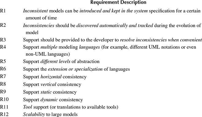
We have identified 12 important requirements (collected in Table 12.1) by analyzing the requirements discussed in the literature for current approaches to model consistency. Requirements R1 to R3 in Table 12.1 originate from the observation that any strategy to manage model consistency should not limit the freedom of developers. This entails that developers should be allowed to modify models even if they introduce some inconsistencies. This idea is introduced in Finkelstein et al. [10], where the authors observe that inconsistency is necessary and often desirable in some phase of the development cycle. For example, in the inception phase of a large project with different stakeholders involved, each stakeholder pursues different goals and, during the collection of requirements, this can lead to inconsistent views that must be identified and reconciled in subsequent iterations. Other arguments in support of Requirements R1 to R3 have been documented elsewhere [11, 12 and 13]. The common denominator of all arguments is that effective modeling techniques must support decomposing the problem into independent subproblems. This is the case when in order to solve complex problems, engineers decompose various aspects of the system and reason about each aspect in isolation. Alternatively, this occurs when in order to solve complex problems efficiently, different teams work in parallel on different aspects of the system.
TABLE 12.1
Requirements for UML Consistency Management
A second observation is that each model caters to different needs that arise during the development process. For example, informal models are used to gather requirements and exchange ideas between stakeholders and developers during requirements gathering [14]. Later in the development process, more formal models are used to describe the structure or the behavior of certain parts of the system. In this phase, formal models are used to verify properties of a system or to generate part of the implementation code. This second observation is the source of the additional requirements R4 to R6 in Table 12.1.
To evaluate consistency management techniques, the notion of consistency must be clearly defined. The scientific literature examines different notions of consistency. A distinction can be made between horizontal and vertical consistencies [15,16]. Horizontal consistency involves different perspectives on the same system model. For example, on the one hand, to describe the communication between a client and a server, it is possible to use a UML sequence diagram to capture the protocol and a state diagram to capture the server behavior. The two diagrams are different views on the same system and should be horizontally consistent. On the other hand, vertical consistency addresses views of the same aspect of one system, but at different levels of abstraction, often in relation to the evolution of one model during different phases of the development process. For example, an abstract model created during requirements gathering must agree with a more detailed model used for code generation in a later step of the development process. Another important distinction is between static and dynamic consistency [17]. Static consistency addresses syntactical and structural model dependencies, whereas dynamic consistency ensures the consistency of executable models. We introduce four requirements (R7 to R10 in Table 12.1) to capture these four notions of consistency.
The final two requirements address practical use of consistency management techniques. Requirement R11 recognizes that consistency checking must be supported by a tool chain. Requirement R12 recognizes that industrial systems are large scale and this implies they have large system models. Therefore, scalability of the chosen technique to large models is an important requirement.
12.2.2 Consistency Checking
In the literature, a number of promising approaches for model consistency checking exist. The existing approaches can be divided into two categories: rule-based approaches and translation-based approaches. The first category uses rule-based systems to define consistency rules directly on the modeling language. In general, rule-based approaches scale well to large models but are limited to addressing only static consistency (failing requirement R10). On the other hand, translation-based approaches leverage a target language with a formal semantics and translate models into this language. Tools that support automated reasoning or formal verification in the target language can be used to reason about the consistency of the origina models. Translation-based approaches can address both static and dynamic consistencies; however, they have very limited scalability and tend to be restricted to a subset of the UML languages (failing requirement R4).
Rule-based approaches translate a modeling language into a logic framework on which the system of rules is defined. The goal of the translation is to be able to apply rules defined on a logic framework. This translation does not aim at defining a formal semantics for the modeling language and does usually limit the expressiveness of consistency rules to structural elements of the language. On the other hand, translation-based approaches leverage languages with formal semantics and the translation process implies the definition of a formal semantics for the UML. These approaches enable reasoning about consistency of behavioral models but tend to work only on subsets of UML and impose the resolution of variation points. Because translation-based approaches are closely related to the problem of defining a formal semantics for UML, we discuss them further in the Subsection 12.2.3.
Table 12.2 summarizes the approaches to consistency that we discuss in this section. Each requirement we identified in the previous section is a column of the table, whereas each of the approaches we discuss here is represented as a row. This section and Table 12.2 cover consistency management approaches that use rule-based systems; a second table in the next section covers approaches that use translation to formal languages. These approaches are important to know, especially if you want to understand the fundamental issues with consistency arising from the flexible, but complex, UML metamodel. Additional consistency problems, such as timing consistency, arise when using profiles for real-time systems, such as MARTE. These problems are not directly addressed by any of the methodologies surveyed.
A logic framework for capturing models and rules has been proposed by Van Der Straeten et al. [18]. In this work, the authors propose the use of description logic (DL), which is less powerful than first-order logic, but is decidable. The approach, which targets a subset of the UML language, proposes to encode UML models and metamodels as well as consistency rules in DL. The focus of this appproach is on both software evolution (vertical consistency) and consistency between different views of the same specification (horizontal consistency). To this end, the UML metamodel is enhanced with classes capturing horizontal and vertical relations. This approach is used, for example, to support model refactoring in [19], which documents how the RACER tool is used to enable inference from the DL knowledge bases. The translation between UML and DL is performed by the RACOoN tool, which enables refactoring and is integrated into the Poseidon UML modeling tool.
Sabetzadeh and Easterbrook [20] present a requirements merging approach based on category theory. The approach aims at merging inconsistent and incomplete views. Views are expressed as graphs, and relations between views are expressed by an interconnection diagram that relates common elements of different views. A colimit operation on the views combined with the interconnection diagram return the integrated view. To address inconsistencies, the methodology supports annotating elements of the graphs to identify where inconsistencies stem from. Annotations are captured via a knowledge lattice that identifies proposed, repudiated, affirmed, and disputed elements. The article, however, does not discuss how this technique can be applied to address the consistency of views expressed in different languages.
TABLE 12.2
Evaluation of Consistency Checking Approaches Based on Rule Systems
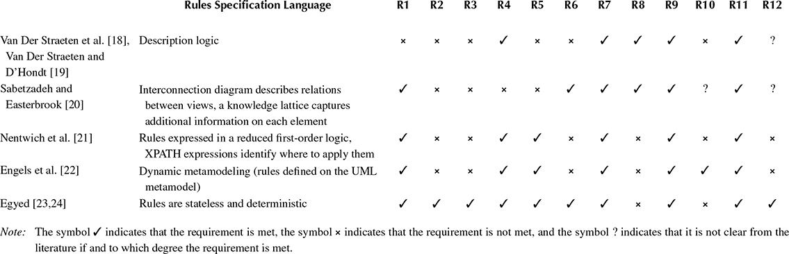
Other approaches proposed in the literature define consistency rules on models represented by XML documents. These approaches can be adapted to work on XML representations of UML models serialized in the XML Metadata Interchange (XMI®) [25] interchange format. For example, a general XML-based consistency checking tool called xlinkit has been used to verify structural consistency; Nentwich et al. [21] present the tool, an incremental algorithm for checking, and a case study. To make rules decidable, they are based on a restricted version of first-order logic. The tool can check XML documents or other types of models by using a “fetcher” that reads the code and creates an in-memory Document Object Model (DOM) from it. Then, xlinkit uses XPATH (a query language for DOM) to specify the parts of the memory model where the rules must be applied. As a result of the rules evaluation, a set of links between conflicting elements is created. This enables the user to navigate the model and resolve inconsistencies without forcing the immediate resolution of every inconsistency. To improve scalability, an incremental algorithm is used to detect which rules have to be rechecked after a change. However, once the tool decides that a rule must be reevaluated, it is reevaluated on the entire model. As a result, when complex rules (such as the language constraints defined by the UML standard) have to be reevaluated, the benefits of this incremental algorithm are limited. The authors claim that the cause of this drawback is the complexity of the XMI representation. The benefits of this technique are the independence from a specific modeling tool (XMI is an interchange standard supported by many tools) and the possibility of distributing the documents over the Internet. Major limitations are the fact that only structural consistency is addressed and that different rule evaluation orders can lead to different results. Moreover, XMI is not interpreted consistently by different tools. Therefore, it is not functioning as an interchange language in practice and consistency checking results could also be influenced by the tool chosen for creating the XMI file.
Other approaches define rules at the UML metamodel level instead of choosing a specific UML representation, such as the XML-based approaches of the previous paragraph. For example, Engels et al. [22] present an approach based on dynamic metamodeling (DMM). Rules are defined on the graphical representation of the UML metamodel using an extended class diagram notation. The extensions include the ability to annotate elements of the metamodel with new and delete keywords. These keywords specify that the corresponding elements are respectively created or removed when the configuration captured by the metamodel is instantiated. The verification of consistency is then performed by testing. Overlapping models are verified in pairs where one is executed according to the DMM semantics, whereas the other is checked to identify violations. This approach has the great benefit of using a graphical model with which UML users are familiar. Drawbacks are that many rules must be defined for UML and that testing is not complete. In particular, the paper does not discuss any form of coverage metric to assess the confidence in the verification process.
Other approaches extend modeling tools. For example, Egyed [23,24] presents an extension to the Rational Rose tool. This extension, which is based on an algorithm presented in Ref. [26] by the same author, supports incremental consistency checking by using stateless deterministic rules. The incremental rule checking algorithm can analyze which part of the model is accessed during the evaluation of a rule and use the information to reevaluate rules only on the relevant portion of the model when changes happen. For each inconsistency identified, the tool creates an inconsistency annotation in a report. This tool is highly scalable and has been used on actual large models in industrial case studies.
12.2.3 Semantics
The second type of consistency checking approaches is closely related to the problem of defining a formal semantics for UML languages. The research community has been very active in defining semantics for UML [27–31]. Broy et al. [29, 30 and 31] give a formal model for UML based on stream semantics [32]. This approach bases the semantics on the elements of the UML metamodel and maps the UML to a formal model that closely matches each element of the metamodel itself. This results in a very complete semantic framework that formally captures every detail of the language, enabling the reasoning about every feature of the UML. However, for the goal of checking dynamic consistency of models, this framework is difficult to use. In fact, model checking tools are used to verify dynamic consistency. Because the translation to the formal model suggested by Broy et al. [29–31] contains all details of the UML, the state space of the models tends to be very large and properties are difficult to verify. Other work by Krüger and Menarini [28] proposes to map each diagram element to a very simple domain model specifically developed for the application domain the model is describing. This simplifies the automatic reasoning about the model properties but loses details about the language. In general, to use the UML and provide a formal semantics, the variation points are resolved and a profile is created to match the modeling needs.
Translation-based approaches for consistency management have been pursued by various authors. Instead of defining consistency rules based on the source models, they translate models into various formal languages and logics. The consistency is then implied by contradiction in the semantics of the target language. One of the main benefits of such approaches is that the translation to the target formal language defines the semantics of behavioral models. Therefore, on the one hand, all approaches following this avenue support reasoning about dynamic consistency. On the other hand, because in the translation the mapping to the original model can be lost, such approaches have greater difficulty in dealing with syntactic and structural rules required by static consistency.
Table 12.3 summarizes the consistency approaches discussed in this section. These approaches are all based on giving a formal semantics to UML by providing a translation to some formal language.
An example of an approach that involves translation is presented by Easterbrook and Chechik [33]. They use the Xbel framework to reason about state machines encoding inconsistent multiview requirements. The approach proceeds as follows. First, multiple state-machine views are merged into a single state machine. Because views can be inconsistent, the system is based on a multivalued logic called quasi- Boolean logic. Next, a multivalued model checker (called Xchek) is used to verify temporal properties expressed in XCTL (an extension of computation tree logic [38]). Translating state machines into their multivalued logic counterparts enables the merger of inconsistent and incomplete models. The Xchek model checker enables the analysis of how inconsistencies affect the execution behavior of the state machines and helps in resolving them.
TABLE 12.3
Evaluation of Consistency Checking Approaches Based on Translation to a Different Semantics
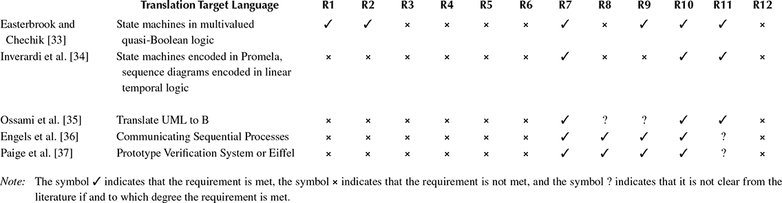
Inverardi et al. [34] use the SPIN [39] model checker to verify consistency of the behavior expressed by overlapping state machines and sequence diagrams. The approach uses Milner’s [40] Calculus of Communicating Systems notation to describe state machines and a stereotype of the UML for sequence diagrams. The paper proposes to translate state machines into Promela (the input language of the SPIN model checker) and to translate sequence diagrams into linear temporal logic (LTL) formulae. SPIN is used to verify consistency by checking that the Promela model satisfies the properties expressed by the LTL formulae. A tool called Charmy supports the creation of sequence diagrams and state machines while it also generates the Promela code and the LTL formulae for verification.
A different solution to consistency checking is proposed by Ossami et al. [35]. The semantics of the UML is formalized by using the B [41] language. This enables developers to verify properties of their systems by using the verification tools supporting B. However, often a developer must modify the B specification to complete the proof. In this case, the two views of the system (UML and B) can become inconsistent. The solution proposed by the authors is to create development operators that map each requested transformation in one domain to equivalent transformations in the other. Therefore, once the correctness of the development operator is proven, it can be applied many times without introducing any inconsistency. This constructive approach has the benefit of reducing the amount of verification to perform. On the other hand, the developer is limited by the existing operators in how to modify the model because the solution does not allow consistency to be broken at any time. The approach of creating development operators is useful in the specific application domain; however, it is not applicable in development processes where inconsistencies are tolerated.
Engels et al. [36] present a translational approach to reasoning about the consistency of UML behavioral models. The approach is used for UML protocol statecharts. In particular, the approach is demonstrated in presence of the inheritance of classes whose protocol behavior is defined by statecharts. Inheritance imposes a refinement relation between statecharts. The paper focuses on vertical consistency, but the same technique addresses horizontal consistency as well. The target language for the translation is Communicating Sequential Processes (CSP) [42]. Rules are defined on the UML metamodel, which defines the UML graphical syntax used to translate the graphical models into the CSP textual notation. Then a tool called FDR (for Failures-Divergence Refinement) is used to verify the refinement relation in CSP.
Two other methodologies making use of translational approaches are presented by Paige et al. [37]. They share the same idea of translating the metamodel of the modeling language into a formal language supported by verification tools. Then each model—instead of being expressed in the original modeling language—is translated into the target language. The modeling language used is Business Oriented Notation (BON); however, UML could be supported as well. In fact, the semantics of the modeling language are completely defined by the metamodel expressed in the new formalism. The two approaches in Ref. [37] differ in the target language. The first approach translates models and metamodels into Prototype Verification System (PVS), a theorem prover language that supports semiautomatic proofs. The second uses Eiffel as a target language. Eiffel is object oriented and supports annotations to define method preconditions, postconditions, and class invariants. On the other hand, translation into PVS is the more flexible of the two approaches as it can encode all details of the metamodels and the verifications are complete. The limitation of PVS is the complexity of the translated models and the fact that it requires manual intervention in the verification process. On the other hand, Eiffel is a programming language and the “verifications” are performed by testing, which can be automated but the results are not complete. The general benefit of this type of approaches is that, because both syntax and semantics are captured by the translated metamodel, it is possible to check all consistency properties of the models. On the other hand, especially if applied to the large UML metamodel, scalability is a serious issue. Moreover, to perform a complete consistency check, developers are forced to use the PVS translation. This creates tremendous issues for the maintainability of large models, especially because the PVS translations cannot be kept from the developer as it is necessary to manually intervene in the verification effort.
From this comparison we see that addressing consistency for a large standard such as the UML is very difficult—even more so when fundamental modeling concepts such as time are not inherent language concepts but are bolted on using profiles and stereotypes. In the following section, we will present an alternative solution to the consistency management of the UML.
12.3 Solving UML Consistency
None of the approaches surveyed in the previous section fully address all requirements of Table 12.1. We believe that the common challenge of previous work is in losing track of the abstractions implemented in the models that are checked for consistency.
Previous work has taken two routes: either analyzing the semantics of the diagrams at the metamodel level (or defining consistency rules between different notation types from there) or translating the models into an existing formal language leveraged for verification. In contrast, we propose an approach that defines an explicit ontology that captures the target domain we are modeling and, further, we define a simple execution framework (similar to a “virtual machine”) based on this target ontology. The ontology concepts map one-to-one onto elements of the system class we are interested in modeling.
The main novelty of the consistency checking approach presented here is in the comprehensive, yet simple mechanism we introduce for specifying consistency rules. By defining a simple “virtual machine” containing the abstraction used in our models, we can treat all UML diagram types as model generators for this virtual machine. Each diagram selects entities of the virtual machine and constrains their structure or behavior. Model consistency is then simply defined as the presence of virtual machine behaviors under the specified constraints.
We encode constraints as a set of logic propositions over elements of our target ontology and reduce the verification of virtual machine behaviors to a satisfiability (SAT) problem. Although the work presented here is specific to UML, the same approach can be leveraged to integrate other modeling languages with UML-like models.
For the proposed approach to work, we first tailor the UML to the target domain that we are interested in—we leverage the UML MARTE profile to target embedded real-time systems. For the purposes of this chapter, we limit ourselves to a subset of the MARTE notations, rich enough for us to show the value of our consistency notion. In particular, the subset we demonstrate in this chapter includes state diagrams, component diagrams, and interaction diagrams. In Section 12.4, we will analyze avenues to extending this approach to a richer subset of UML 2.0 and to other modeling languages.
12.3.1 Queries and Constraints Semantics
To provide the backdrop for our definition of model consistency, we provide a formal semantic framework based on an abstract model of distributed reactive systems, similar to a “virtual machine.” We call this model of our target domain the “abstract semantic space.” In this space, we show how each element of a model can be interpreted as a constraint on the system. The consistency property can then be trivially defined over the “abstract semantic space” as the existence of a system in that domain satisfies all constraints imposed by the models.
Our semantics is based on two elements: queries and constraints. Each model element of a UML specification is interpreted as a set of (query, constraint) tuples. Each query selects some elements in the “abstract semantic space” that we have defined where the corresponding constraint defines a restriction on the structure or behavior of these elements in a system satisfying the specification. The key benefits of our approach are (1) a mathematically simple, yet comprehensive definition of consistency, (2) the ability to tie the reasoning about consistency to entities of the target domain—resulting in a nongeneric model subclass to which the consistency notion applies, and (3) the interpretation of model elements as constraints over the target domain.
Our consistency checking approach contrasts with other translation-based approaches that we surveyed in the literature in the way we perform the translation. In fact, the target model of our translation abstracts the main components of the target implementation domain. The semantics is then specified by directly mapping each element of the UML model onto some configuration of the target model. Our first step is to define an ontology for real-time distributed systems. This ontology is used to assign precise semantics to the UML models we use and is formalized with Queries and Constraints. This step allows us to formally reason about the specification (using first-order logic). After the formalization, we present the grammar of a language to describe systems based on the target ontology formalism. This step enables the translation of UML models to the new domain. The final steps are the definition of the semantics for our abstract language and, based on such semantics, the definition of consistency.
Figure 12.2 captures the core elements of our ontology for distributed systems with real-time constraints. A real-time system in our ontology is described by five types of elements: two elements, Entities and Channels, form the structural configuration of the system; another two, Messages and Properties, define the behavior; and the Clock captures real-time constraints.
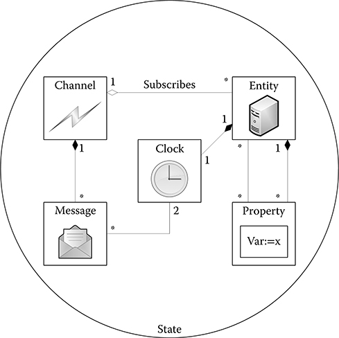
FIGURE 12.2 Core elements.
An Entity captures the concept of a process in a distributed system. An Entity has local variables, captures state information, has computational capabilities, and can communicate with other Entities by means of sending and receiving messages over channels. Channels are the communication infrastructure. Each entity that must send or receive messages subscribes to a channel. Channels transport Messages. When a message is sent on a channel, all entities that have subscribed to the channel eventually receive the message. Properties can be used to capture variables and their state. Each entity has a named set of properties that can be evaluated at runtime. Finally, the Clock captures the time relative to an entity. We could have used different notions of time, the choice depends on the type of system we intend to model and the profile of UML we use. MARTE supports not only the type of time we model here but also other time models, for example, modeling of synchronous reactions.
Figure 12.2 shows these five core elements forming the abstract state of the system. At each instant, the structural part of the system state is defined by the existing Entities and Channels and by the subscription of Entities to Channels. The behavioral part is defined by the Messages exchanged on each Channel and by the internal state of each Entity defined by the valuation of its Properties. Timing relations are expressed by the collections of all clocks associated to entities. Each Entity has its own reference of time given by the clock. At any given instant, when we capture the state of the system, different clocks can have different time values. It is interesting to note that, because the state comprises both a behavioral and a structural part, it is possible to represent a reconfiguration of the system as a change of state.
Based on the concept of state, we can now define a run as an infinite sequence of states (cf. Figure 12.3). In turn, we now define the semantics of a system based on runs. In Figure 12.4, we show the full ontology that we use to assign a semantics to UML. A system is defined by a set of runs. A specification defines a set of acceptable runs. The specification can constrain the acceptable runs by specifying the initial states and the acceptable transitions.
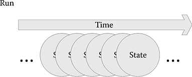
FIGURE 12.3 Definition of a run.
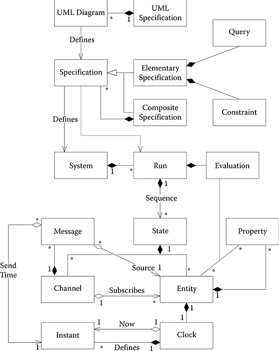
FIGURE 12.4 Ontology for distributed real-time system semantics.
Another interesting element of Figure 12.4 is the definition of Specification. A Specification can either be composite or elementary. Every Elementary Specification is made up of two elements: Query and Constraint. A Query selects states from all possible runs while the corresponding Constraint defines the characteristics for the run to be acceptable. We can think of the selector as an operator that is applied to all possible runs. All states selected by the Query are compared with the rules specified in the constraints. If they match, the run is accepted as part of the system whereas if they do not match, the run is discarded.
An important point to notice is how time is treated in the ontology. Each Entity has access to one private Clock. The Clock defines a series of Instants. At any given time, the Clock refers to one of the instants as Now. Each message has one Send Time (an instant on the clock of the entity that sends the message) and one Source Entity (the sender of the message). Therefore, it is possible to reason about when each Message was sent and by which Entity. Messages can be received by different Entities at different times. When an Entity that has subscribed to a Channel receives a Message, it can identify the local Entity time using its Clock and obtain the time of the sending Entity from the Message. Depending on the system and the requirements, it is possible to define synchronization strategies between the Clocks so as to be able to reason about times of events across different Clocks.
We can now give a formalization of the semantics informally described above. To this end, we first formalize the concepts of state and run as a foundation for the semantics of a distributed system specification. Then we present a simple grammar for a specification based on Queries and Constraints and use the formal definitions introduced before to provide a semantic for it.
12.3.1.1 Notational Preliminaries and System Formalization
We represent sets with capital Greek letters. For instance, the set of properties will be represented by Ψ. Each element of the set will be represented by the corresponding lowercase letter. For instance, a property in Ψ would be represented by Ψ. A function from a domain A to a codomain B is expressed as φ: A → B. A tuple is defined as y = (y1, y2,…) ∈ Y1 × Y1 × … and πi ⋅ y = yi is the projection operator returning the ith element of the tuple. Given a set X, Р(X) is the power set of X, where |X| returns the cardinality of X. Furthermore, with ![]() we indicate the set of Boolean values (true and false), ℕ the set of natural numbers, ℕ+ the set of natural numbers without 0, and ℕ∞ with the set of natural numbers with its supremum ∞.
we indicate the set of Boolean values (true and false), ℕ the set of natural numbers, ℕ+ the set of natural numbers without 0, and ℕ∞ with the set of natural numbers with its supremum ∞.
A stream [32] is a finite or infinite sequence of Messages. Given a set of Messages M, we indicate with M* the set of finite sequences over M, with M∞ the set of infinite sequences, and with Mω the union of those two sets. We can obtain the ith element of a stream x by using the infix dot operator x.i. The notation x ↓ i returns the prefix stream of length i, whereas x ↑ i returns the tail stream obtained by removing the first i elements from x. The concatenation of two streams x and x′ is denoted as x ↷ x′. We overload this notation to work with sets of streams X ↷ X′ such that the resulting set contains all streams of the form x ↷ x, where x ∈ X ∧ x′ ∈ X′.
We can now give a formal definition of the elements of our ontology. For the two structural elements, Entities and Channels, we define two sets: the set E of Entities and the set X of Channels. For each Channel χ we have a set sigma ∑χ keeping track of the Entities subscribed to χ. A Channel valuation relates the Channels (ele ments of the set X) to Messages exchanged over the Channels. Because a Channel can be used to send multiple Messages at any given moment, for every Channel χ we define a set Mχ of Messages currently sent over it. Furthermore, for each Entity ε we define a set Ψε of Properties. A special Property vε encodes the current time of entity ε’s Clock.
State is defined by (1) a structural configuration formed by Entities, Channels, and the subscriptions of Entities to Channels; (2) a behavioral configuration formed by Messages on each Channel, and valuation of Properties for each Entity; and (3) the current time value of the Clock property for each Entity.
Properties are intended to encode the state of an Entity. To abstract from the concrete data types used to define the variable space we define a set of functions Φ. Each φ ∈ Φ is a function defined from the values of a tuple of Properties to a Boolean: . This allows for easy translation of UML specifications. For instance, if we want to model a UML Deployment Diagram specifying that a node would run a particular program P, we can define a function run and have it evaluate to true on the entity corresponding to the node (run(P) = true). The evaluation of the function set Φ over an entity ε is defined as .
We can now define structural configuration as
We define behavioral configuration as
We define state as
where State is an element of the StateUniverse set containing all possible states.
We can now define the concept of a run using streams: Run StateUniverse∞. The semantics of a system specification in this framework emerges as the set of admissible runs:
12.3.1.2 Abstract Specification Language
We now define the abstract language we use to specify Queries and Constraints (and, therefore, systems). The benefits of defining this language are twofold. First, it provides an explicit context for mapping specifications (both composite and elementary) to systems in the semantic framework. Second, it provides a target language for the UML translation. The goal of the language is not to introduce a new textual syntax, and, therefore, we keep it simple by ignoring punctuation and other syntactic sugar necessary for a complete textual language definition.
We present the grammar of the language in a Backus–Naur Form using production rules of the following form:
Nonterminals are enclosed in angular brackets, the symbol || separates alternative productions, optional terms are enclosed in square brackets, and the notation {T}* represents the repetition of term {T} for 0 or more times.
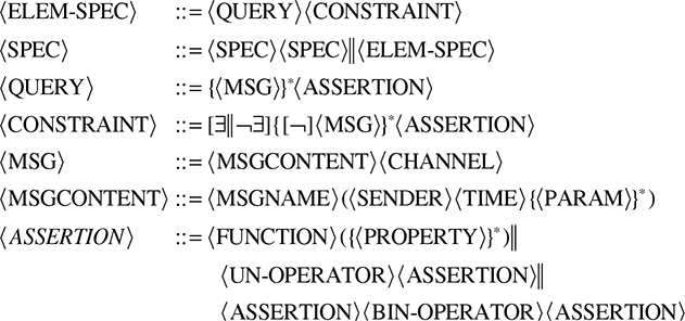
Operator definitions are not part of this grammar. Instead, they will be introduced when necessary in the translation of UML. In particular, we express all unary operators with the nonterminal 〈UN-OPERATOR〉 and binary operators withc 〈BIN-OPERATOR〉. 〈FUNCTION〉 is a Boolean formula from property names to Boolean. Using this grammar, we can specify a system based on the ontology we have devised using Queries and Constraints. In the next section, we define the semantics of such specifications.
Using the 〈CONSTRAINT〉 optional operators ∃ and ¬∃, it is possible to affect the structure of the system. We use ∃ to create new entities and channels, ¬∃ to remove them.
Time is addressed in this language as a property of entities. In particular, we use the notation next(t) to indicate the value of an entity clock in the first state where the value is greater than t. With next we are able to reason about next states without constraining their occurrence to a particular time value. Moreover, the messages contain the 〈SENDER〉 entity and the sending 〈TIME〉 of the message in its parameter list.
12.3.1.3 Specification Language Semantics
An elementary specification 〈ELEM-SPEC〉 is captured in our abstract language by a tuple 〈QUERY〉, 〈CONSTRAINT〉. The goal of a specification is to define what runs are part of a system implementing such a specification. The 〈QUERY〉 identifies what parts of the run the specification is constraining, whereas the 〈CONSTRAINT〉 specifies how those parts are constrained. A run that fulfills a pair of query and constraint is such that in all states following a state where the query is true the constraint is true. Therefore, an 〈ELEM-SPEC〉 encodes a transition function between two states.
We define a 〈QUERY〉 as a communication context selecting the states that follow a particular message interaction, and a Boolean formula over properties, which identifies states to constrain. A query thus addresses both the contents of channels (the channel history) and predicates over the local data state of the relevant entities. We first define the channel configuration Xc as
This definition captures the part of a state S that specifies the channel configuration and the messages being exchanged in the given state. The semantics 〚q〛 of a 〈QUERY〉 q is, therefore,
where Xc* is a finite stream of channel configurations, the channel history h ∈ P(Xc*) is a set of such streams, and the assertion a is a function from a set of properties to Boolean values.
We define a helper function
that, given a 〈QUERY〉 semantics and a run, returns a set of tuples containing (1) the indexes of the states where one of the message histories is matched and (2) the corresponding set of entities for which the evaluation of the function is true. This helper function gives us all states in the run where we have to constrain the next state, as well as the corresponding entities to be constrained.
〈CONSTRAINT〉 is defined as a tuple of channel configurations, Boolean functions over properties, and one of the three quantifiers {∃,¬∃,–}. Similar to what we did for queries, we define the semantics of 〈CONSTRAINT〉 as
We can define a helper function
where constr takes as arguments a run, the result of a query operation, and the semantics of a constraint. This function returns true if the constraint is satisfied. To be satisfied, the channel configuration of the selected states must match the Xc specified by the constraint. Moreover, how the rest of the constraints is satisfied depends on the choice among the three quantifiers {∃,¬∃,–}. If the chosen quantifier is –, the assertion s must evaluate to true in all entities selected. If the quantifier is ∃, the assertion s must evaluate to true in some entities not part of the selected ones. Finally, if the quantifier is ¬∃ the selected entities must not be present in the selected states.
Now we can define a 〈SPEC〉 in the semantic domain as a set of tuples of the form (query, constraint), and the system corresponding to the specification as the set of all possible runs that fulfill all such tuples (query, constraint) of the set.
Formally,
12.3.2 Notion of Consistency
We are interested in defining dynamic consistency for real-time distributed systems. This is the reason why we have tailored our semantic framework to this domain rather than staying within the generality of the UML language metamodels. Given the semantic framework presented in the previous section, it is now straightforward to define dynamic consistency for models in this system class. We will first define horizontal consistency and then vertical consistency.
We can define horizontal consistency as follows: a specification is horizontally consistent if the system it defines admits at least one run. This is consistent with the definition of horizontal consistency we gave before. In fact, a specification 〈SPEC〉 is formed of multiple views at the same level of abstraction (in our formalism this means multiple sets of query and constraint tuples).
Definition 12.1
A specification 〈SPEC〉 such that 〚〈SPEC〉〛 ∈ P(StateUniverse∞) is horizontally consistent iff 〚〈SPEC〉〛 ≠ ∅.
This definition captures the idea that the specification is implementable. There are two possibilities for a system to fulfill this property. Either there are no contradictions in the specification or the admissible runs do not match any query that defines inconsistent constraints. There is nothing wrong in using different perspectives to constrain the system behavior specified by other perspectives. However, if a perspective constrains the behavior of the system such that no run satisfying the specifications of that perspective is allowed in the final system, there can be a consistency problem. A stricter rule for horizontal consistency requires that the system has at least one run admissible for each perspective, meaning that there is at least one run satisfying some queries of each perspective specification.
Definition 12.2
A specification 〈SPEC〉 such that 〚〈SPEC〉〛 ∈ P(StateUniverse∞) and 〈SPEC〉 made of N specifications 〈PERSPi〉 called perspectives such that 〚〈SPEC〉〛 = ∩i∈N〚〈PERSPi〉〛 is horizontally consistent iff ∀ 〚〈PERSPi〉〛, ∃Run ∈ 〚〈SPEC〉〛 ∧ ∃s ∈ 〚〈PERSPi〉〛 such that query(s.0, Run) ≠ ∅.
A possible problem with our first definition of horizontal consistency is that we could have a system specification with no runs satisfying any query of the general specification. The consistency specification for such a system is vacuously satisfied (i.e., runs are possible because selectors never match). The second definition solves this problem requiring that some runs matching the specification queries are present.
The two definitions of horizontal consistency we gave support two different usage scenarios. In fact, we can identify two main reasons to create a specification. First, we can be interested in constraining how the system works in a given scenario. The scenario we want to constraint must, therefore, be possible and the corresponding query must select some runs. For this type of usage we should use consistency Definition 2. A different use case is when we want to specify recovery from some failure of the system. For example, we may identify that a given interaction can happen as a result of a failure even if the specification would not allow for it. In this case, the goal is to describe the detection and recovery from a given failure. In this case, we can use consistency Definition 1.
Vertical consistency is defined between two specifications at different levels of abstraction. We can define this consistency notion by a containment relation between runs. If we have a more abstract specification SPECa and a more concrete specification SPEC c, we define vertical consistency as follows: a concrete specification SPECCa if all runs allowed in the concrete system specification are also allowed in the abstract one. Moreover, the abstract system allows runs that the concrete system does not allow. This definition requires that the concrete systems admit a strict subset of the runs admitted by the abstract one.
Definition 12.3
Two specifications SPEC and 〈SPECa〉 is consistent with an abstract specification 〈SPECc〉, where the first is the abstract and the second the concrete specification, are vertically consistent iff 〚〈SPECa〛 ⊆ 〚〈SPECc〛.
Given the definitions of 〈SPEC〉 and 〚〈SPEC〉〛 of the previous section, we can now define a modularity theorem. We first observe that each specification has a set of tuples containing one query and one constraint. Therefore, each of these tuples defines a set of runs. From the definition of 〚〈SPEC〉〛, we can infer a lemma asserting that the semantics of a complex 〈SPEC〉 (i.e., formed by multiple tuples of query and constraint) is the intersection of the semantics of all the subspecifications formed by single query/constraint tuples. The modularity theorem states that for any complex specification 〈SPEC〉 we can always identify two subspecifications such that the intersection of the runs permitted by the two contains exactly the runs permitted by the original specification. Moreover, the theorem states that, to obtain such subspecifications we can simply take two subsets of the tuples of the original specification, provided that all tuples of the original specification are in at least one of the two subspecifications. Now we can formally define the lemma and the theorem as follows.
Lemma 12.1
Given a specification 〈SPEC〉
Proof: Lemma 1 can be proved by observing that the definition of 〚〈SPEC〉〛 is such that if a specification contains a single query/constraint tuple t, the ∀ quantification in ∀s ∈ 〈SPEC〉 return a single element. Therefore, we have
given the definition of intersection: ∩∀s∈S s = {e : ∀s ∈ S, e ∈ s}. Replacing the specification of the semantics of a query/constraint tuple into the definition of intersection we obtain
From this, by replacing e with the definition of Run we obtain
which is our definition of 〚〈SPEC〉〛.
The Modularity theorem asserts that complex query/constraint specifications can be split into two simpler ones without losing information.
Theorem 12.1
Modularity. Given a specification 〈SPEC〉 such that |〈SPEC〉| > 1 (i.e., the specification is complex), ∀〈SPEC1〉, ∀〈SPEC2〉 such that
The proof of Theorem 12.1 derives easily form Lemma 12.1. In fact, because the semantics of a specification is equivalent to the intersection of the semantics of all its constituent query and constraint tuples, we can use the commutative and associative properties of intersection to prove Theorem 12.1.
12.3.3 Example of Consistency Management
To show how the methodology outlined in this chapter applies to consistency checking in the context of UML for real time, we are required to provide a translation from UML and from its MARTE profile to the abstract language we introduced. Translating the entire UML and MARTE metamodels is beyond the scope of this chapter. Instead, we chose a simple subset of UML and MARTE that uses three graphical notations: component diagrams, sequence diagrams, and state diagrams, which we used in the example of Figure 12.1. Furthermore, we translate MARTE timed constraints as we used them in our example.
The translation from UML models to our query and constraint language assigns a precise semantics to each model. Several options for assigning semantics to each notation exist. For the sequence diagram, for instance, we have many possibilities for interpreting them existentially (at least the specified behavior must be possible) or universally (precisely the specified behavior is required) [43]. Notice that the decision of interpreting the diagrams existentially or universally depends on what the goal of the specification is. For example, in a requirements document an interaction can exemplify one of many possible scenarios and the existential interpretation would be correct. For real-time systems modeling we interpret sequence diagrams universally. All messages exchanged in the system must be represented in diagrams. This interpretation of sequence diagrams is viable for our application domain. In fact, one of the key uses of models of communication in real-time systems is to analyze the network traffic and ensure that real-time constraints can be met. To this end a complete view of which messages are exchanged over the communication channels is necessary.
Our translation strategy interprets every element of a UML graph as a query and constraint tuple. We introduce an operator to compose those elementary specifications—this closes the loop with the introduction of the abstract query/constraint syntax. For demonstration purposes, we introduce the parallel operator. This operator is applied between any two specifications in our translation and returns the specification containing all query and constraint tuples of the operand specifications.
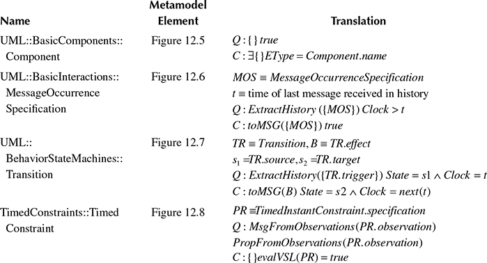
In Table 12.4, we provide translation rules for some of the interesting model elements used in our example. The entire set of rules is beyond the scope of this chapter. Each rule provides a set of query/constraint tuples that can be composed in a specification using the parallel operator. To support the translations, we define a small set of helper functions.
TABLE 12.4
Translation Rules for Uml Metamodel Elements
The function toMSG() is used to convert two elements of the UML metamodel, MessageOccurrenceSpecification and Triggers, into objects suitable for our abstract language. Informally, we can think of MessageOccurrenceSpecification as representations on sequence diagram lifelines of the events related to message sending and receiving (plus execution of actions and other details we do not consider in our simplified model). The function toMSG() expresses the translation from OccurrenceSpecification elements of the UML metamodel to messages in our abstract language specification.
Similarly, the ExtractHistory() function applied to a model element of type MessageOccurrenceSpecification returns the sequence of messages that maps to the Events in the lifeline before the one defined by the given MessageOccurrenceSpecification. Intuitively, this function returns the history necessary for a query to select the correct interactions before applying the constraint to match the message event defined by the MessageOccurrenceSpecification model element. We do not describe the details of how this translation is performed because it is beyond the scope of this chapter. In fact, the UML metamodel is very complex. Extracting relations between events and specification elements in different diagrams often requires the exploration of a deep class hierarchy. For example, by inspecting the metamodel of Figure 12.6, we can observe that to extract the history of events before a given message in a sequence diagram, we have to identify the Lifeline the OccurrenceSpecification is covered by. Then, leveraging the fact that the set of events of a lifeline is ordered, we could extract all the OccurrenceSpecifications that precedes the one for which we are creating the history. Once we have the ordered list of OccurrenceSpecifications in the history, we can navigate their event property to obtain the corresponding Events. By reflection, we can identify the events that are related to sending and receiving messages and use this information to generate the list of message specifications.
The four translations given in Table 12.4 map the elements of UML and MARTE metamodels depicted in Figures 12.5 through 12.8 to query and constraint tuples. The first line of the table gives a translation for Figure 12.5. This part of the metamodel defines UML components in a component diagram. The simple model in the figure captures the relation between Components and Interfaces, which can be required or provided by the Component. Our translation simply asserts that a specification of a component always imposes the existence of an entity with a property called EType and value equal to the component name in the UML diagram.
The translation of line 2 of Table 12.4 defines constraints imposed by a MessageOccurrenceSpecification in a UML sequence diagram. The query extracts the message history before the given MessageOccurrenceSpecification. As we already mentioned discussing ExtractHistory, this is not a trivial operation. Figure 12.6 presents the relevant subset of the UML model for sequence diagrams. Interactions are the type of behavior specified by this type of diagram. In particular, an Interaction is a type of InteractionFragment that can be composed of other such fragments. Special types of InteractionFragments are OccurrenceSpecifications which reference communication Events and Lifelines. An example of such specifications is MessageOccurrenceSpecifications, which represent messages exchanged according to the interaction modeled. The constraint in our translation is the existence of the message corresponding to the MessageOccurrenceSpecification. This translation covers only events that are messages. Other types of events cause properties in some entity to be set and are not covered in our example.

FIGURE 12.5 Subset of the UML Component metamodel. (Adapted from Object Management Group, “Unified Modeling Language (OMG UML), Superstructure, Version

FIGURE 12.6 Subset of the UML Message metamodel. (Adapted from Object Management Group, “Unified Modeling Language (OMG UML), Superstructure, Version 2.3.” 2010, formal/2010-05-05, OMG.)
The third line of Table 12.4 defines a Translation for state-machine transitions. To this end, we introduce an entity property named State. Figure 12.7 depicts the relevant subset of the UML metamodel for state-machine diagrams. According to the UML metamodel, a Transition has a source and target Vertex, and State is a type of Vertex. A Transition can be taken only if the guard constraint is true and, in this case, is taken when a given trigger occurs. Moreover, a Transition can have an effect. The effect is a Behavior. An example of Behavior is the Interaction (as depicted in Figure 12.6), which can contain message-related events (because MessageOccurrenceSpecifications are also InteractionFragments). For our case study, we simplify the translation to address just triggers and effects that are messages. The query part of the translation of Transition selects entities, where the State variable coincides with the source state of the model. Other propositions in the query can be used to restrict the selection to only specific entities. In fact, state diagrams define the behavior of particular model elements. For example, in our case study we want to apply the state diagram of Figure 12.1c only to the component Emergency Brake. In this case, the query should also limit the selection to states of the entity Emergency Brake. To this end, we can add to the query another clause that selects only entities of the correct type (i.e., EType = “Emergency Brake”). The other part of the query limits the selection to states where the trigger message is present. The constraint simply forces the next state of the selected entities to have the target state in the State property.
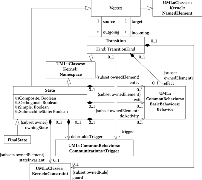
FIGURE 12.7 Subset of the UML Transition metamodel. (Adapted from Object Management Group, “Unified Modeling Language (OMG UML), Superstructure, Version 2.3.” 2010, formal/2010-05-05, OMG.)
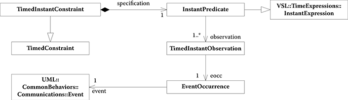
FIGURE 12.8 Subset of the MARTE TimedConstraints metamodel. (Adapted from Object Management Group, “UML Profile for MARTE: Modeling and Analysis of Real-Time Embedded Systems, Version 1.0.” 2009, formal/2009-11-02, OMG.)
Finally the last line of Table 12.4 defines the translation for MARTE TimedInstantConstraint. Figure 12.8 shows the relevant MARTE metamodel. A TimedInstantConstraint has a specification that is a predicate over a set of observations (TimedInstantObservations). Each observation identifies an event occurrence. EventOccurrences relate MARTE observations to UML Event elements. MARTE introduces the Value Specification Language (VSL) to formulate algebraic and time expressions. The translation of MARTE InstantPredicates has to interpret the VSL InstantExpression. To this end, in our translation, we use an evalVSL Boolean function that evaluates a VSL expression. Moreover, we use two functions, MsgFromObservations and PropFromObservations, to obtain the messages and properties that correspond to the events referred to by the observation of a predicate. From Figure 12.8, we can observe the complexity of obtaining an event from a TimedConstraint. Obtaining messages and properties from events requires a good understanding of the UML metamodel and the exploration of many nested relations. Although complex, those functions can be implemented in a program. The translation then selects the correct messages and entities in the query part of the specification and asserts that the specification in VSL evaluates to true in the constraint.
We can now show how to detect inconsistency with this query and constraint framework using the example of Figure 12.1. Thanks to the modularity theorem defined in the previous section, we can split each specification into simpler specifications. In particular, because the intersection of the specifications obtained with the modularity theorem is equivalent to the original specification, we can prove inconsistency by just translating a subset of the model and proving that such subset is inconsistent (no runs allowed).
For example, we can translate the model element of Figure 12.1b that represents the sending of an Ack message from the Emergency Brake to the Train Controller. This translation, according to Table 12.4, would look like
The translation of the Figure 12.1c transition triggered by the Commands Received message is
and
Let us analyze the type of runs that satisfy the translation of the sequence diagram. We can observe that, for a run to satisfy the specification, if in a state there is a Commands Received message received by the Emergency Brake component, it must send an Ack message. In the sequence diagram translation, we do not specify if there is some other action local to the Emergency Brake. In fact, our simplified translation for sequence diagrams deals only with messages sent and received, not local actions. So the message can be returned immediately (next state) or after some local transitions (that is the meaning of {}*, which represents a sequence of zero or more states where the channel is empty). The specification, however, is clear in identifying that no other messages are sent or received by Emergency Brake before returning a message.
The translation of the state diagram of Figure 12.1c triggers a transition from Wait Commands to Reset Timer when the Commands Received message is received by Emergency Brake. We can identify the inconsistency by observing that all runs that fulfill our translation for Figure 12.1c never send the Ack message. The intersection of sets of runs identified by the two specifications is, therefore, empty. Thus, the two specifications are inconsistent.
In our formalism, we can prove consistency by composing query and constraint tuples and identifying contradictions. In particular, we chose to encode queries and constraints using Propositional LTL formulae [44]. The encoding changes for each definition of consistency. We can then prove that a system is consistent according to the chosen definition by proving that the LTL formula that encodes such definition is satisfiable. This proof can be automated by means of a SAT solver for LTL formulas. Examples of algorithms for assessing SAT of propositional LTL formulas and tools implementing them can be found in Goranko et al. [45] and Rozier and Vardi [46].
In this chapter, we do not give a complete translation for all definitions. Instead, we use the example of inconsistent specification from Figure 12.1b and 12.1c and encode the query and constraint specification to prove inconsistency according to Definition 1. For each tuple of query (Q) and constraint (C), we create the implication Q ⇒ XC, where X is the next operator in LTL. If we can find a set of variables that satisfies the disjunction of all these implications, the specification is consistent according to Definition 1.
We capture this in the following theorem.
Theorem 12.2
Consistency D1 Satisfiability. Given a specification 〈SPEC〉, 〈SPEC〉 is consistent according to consistency Definition 12.1 iff the expression ∧∀(Q,C)∈〈SPEC〉 Q ⇒ XC is satisfiable.
In this theorem, we assume that messages in the channel history are encoded using appropriate variables and nested temporal operators. The exact discussion of how to encode these messages is beyond the scope of this chapter. The proof of Theorem 12.2 follows from the definition of 〚〈SPEC〉〛. In fact, the semantics of 〈SPEC〉 is defined as the set of runs that satisfy all query/constraint tuples. We encode each tuple as an implication in LTL that is true if a run satisfies it. The conjunction of all the LTL implications is true only if a run satisfies all of them. If the formula in Theorem 12.2 is not satisfiable, there exists no run that can satisfy all implications at the same time, thus 〚〈SPEC〉〛 is empty. On the other hand, if the expression is satisfiable, there exists at least one run that can satisfy all queries and constraints, thus 〈SPEC〉 empty. This proves Theorem 12.2.
Now we can consider how Theorem 12.1 and Theorem 12.2 apply to our example. From Theorem 1 we know that to prove inconsistency we are not required to compose all the queries and constraints. Instead we can split the specification into two sub-specifications, and the original one will be equivalent to the intersection of the new specifications. Then, if we can prove that one of the two is empty we know that the full specification must be inconsistent. We chose to compose only the specifications of Figure 12.1b and 12.1c. We prove that this subspecification is inconsistent (i.e., has an empty set of runs) and from Theorem 1 we obtain that the full specification is also inconsistent.
Consider all runs satisfying the translation of the transition from Wait Commands to Reset Timer in Figure 12.1c. We identify all runs with a trigger message Commands Received and a transition in the entity Emergency Brake with State changing from “Wait Commands” to “Reset Timer.”
Because the constraint of this specification is the query of the translation for the transition from Reset Timer to Wait Commands in Figure 12.1c, if we compose the two specifications, we obtain all runs where Emergency Brake reacts to a Commands Received by changing two states without sending any message.
We can now compose the current system into the translation of the Ack message specification in Figure 12.1b and discover that one of the next states of the runs selected must send an Ack message before any other messages are received by Emergency Brake. However, from state Wait Commands the system can exit only if the trigger message Commands Received is received. Therefore, by exploring specification tuples we can argue that because the Clock time greater than t1, at which the Ack message must be sent by the sequence diagram constraint, is finite and the specification of the state diagram does not allow any transition that sends messages without receiving anything from the state that it enters after the trigger message, we have a contradiction, and, therefore, the specifications are inconsistent.
If we observe the specification of the state diagram in Figure 12.1d, we can give the following translation for the transition from Reset Timer to Wait Commands:
With this change, the composition of the specifications for the state machine identifies a sequence of states initiated by the trigger message Commands Received that ends with the sending of an Ack message. In the composition with the specification from Figure 12.1b, we have that the state where the Ack message is sent must happen at a time next(next(t″) that is greater than t1. Therefore, there is no contradiction between constraints and, thus, no inconsistency. To prove that the entire specification is consistent we would be required to add the translations of the remaining elements. Although this process is long and error-prone if performed by hand, the existence of automated tools for solving the SAT problem makes it a viable solution.
12.4 Discussion
In this section, we discuss our consistency checking approach, including its strengths and weaknesses. We demonstrated our approach for consistency management based on queries and constraints on a reduced subset of UML and its MARTE profile. The goal of this work was to demonstrate the feasibility of the approach by providing a case study where we were able to identify inconsistencies in UML models. Thus, the translation we gave assigned a semantics only to a subset of the modeling elements defined in UML and MARTE. However, even using this reduced subset we were able to detect and formally verify the inconsistency between models of our BART case study including timing constraints. Because our translation binds query and constraint tuples to single entities in the UML metamodel, an extension to the full language definition of UML 2.0 and its different profiles is straightforward, albeit complex. Such an extension requires us to decide on a precise semantics for each diagram. Therefore, we must fix how each syntactic element of each diagram contributes to its semantics.
Tailoring our consistency notion to a particular target domain (real-time distributed systems in this case) may, at first, seem limiting. However, we argue that a completely general definition of consistency for a general purpose language such as UML ultimately limits the applicability of consistency checking to very abstract models or to purely structural notions of consistency (without taking the notion of behavior into account). This claim is supported by our analysis of the related work. We observe in Tables 12.2 and 12.3 that all approaches that dealt with behavior consistency translated UML to some other language supporting a specific target domain. Similarly, our approach precisely defines the semantic space for both structural and behavioral consistency—albeit at the expense of complete generality. If we decide to target a different domain, a new target model and updated translation rules are necessary.
Different decisions in how to interpret diagrams can lead to different translations. For example, we decided to interpret sequence diagrams universally regarding the messages exchanged. Each message represented in the diagram is exchanged and messages not represented are not. In contrast, state transitions are not part of our translation of sequence diagrams. This is why we set the Clock in the query of row 2 of Table 12.4 as greater than the time the previous message was sent without setting a specific interval. This is equivalent to a commitment to eventually have a state in which the constraint is true.
The definitions of horizontal and vertical consistencies we gave seem adequate for the domain of real-time systems. However, when a richer subset of UML will become amenable to translation and more experience is acquired in verifying it, we see potential for reevaluating the definitions. One possible area of concern with the current definition arises when we allow side effects between the queries and constraints of multiple diagrams, in other words, nonlocal constraints. In this case we could change the definition of horizontal consistency, for instance, to yield inconsistency if the majority of the queries do not match.
The benefit of moving from the abstract domain of UML metamodels to the query and constraint abstract language is that the translation rules define the semantics and implicitly also the consistency rules. We can then avoid enumerating a long list of consistency rules and obtaining a very simple definition of consistency.
With this approach, we have converted the problem of detecting the consistency of graphs based on the UML metamodel to verifying emptiness of sets. The sets are defined by logical formulae, each defining the effect of one model element on the system runs. The composition of specifications is defined by set intersection. Additionally we have presented a modularity theorem (Theorem 12.1) that enables reasoning on separate subsets of the query/constraint specifications. This setup is amenable to translation into propositional LTL and supports use of many automatic formal verification tools, such as SAT solvers. We have provided Theorem 12.2 that affirms the equivalence of proving that an LTL expression is satisfiable with horizontal consistency of the corresponding specification.
We evaluate the query and constraint approach we proposed by identifying how it addresses the 12 requirements we identified in Table 12.1.
R1. Support inconsistent models. We address this requirement by not forcing the user to remove inconsistencies. Models that are inconsistent can be identified by identifying the tuples that are in contradiction. More modeling elements can be added and more contradictions detected before the system is made consistent.
R2. Automatic inconsistency discovery. Inconsistencies are discovered by hand in our example. The goal was to show the complexity of the problem and a possible solution. It is possible, however, to automate translation (which leverages the UML metamodel used by all UML modeling tools) and detection to discover inconsistencies automatically. Furthermore, inconsistencies can be tracked by identifying the subset of specifications that are in contradiction.
R3. Support inconsistency resolution. The support to resolve inconsistencies is provided by the ability to identify a small subset of the specification that is sufficient to prove the inconsistency (this property stems from the Modularity Theorem).
R4. Support multiple modeling languages. The query and constraint approach supports multiple languages by creating different translation rules from the UML metamodel to the abstract target language. It could also support languages that are not UML as long as they are based on a metamodel and a translation is provided.
R5. Support different levels of abstraction. We have identified different consistency rules and translation rules to support different levels of abstraction.
R6. Support extensions. We demonstrated the support for extensions of UML providing a translation rule for the MARTE profile.
R7. Support horizontal consistency. We provided two horizontal consistency definitions.
R8. Support vertical consistency. We provided one definition for vertical consistency.
R9. Support static consistency. This approach supports static consistency by querying entity properties and channel messages and by constraining them.
R10. Support dynamic consistency. The approach supports dynamic consistency by constraining the properties of different states in admissible runs. By leveraging LTL logic and the Clock, it is possible to set constraints on consecutive states or future states.
R11. Provide tool support. While we have not provided any tool support for this approach, we have demonstrated that a translation of the consistency problem to SAT of LTL formulae exists (Theorem 12.2). The translation from UML to another domain can be automated and because we can encode queries and constraints in LTL, we can use existing SAT solvers for this logic to automate the verification.
R12. Address scalability. Thanks to the modularity theorem our approach does not require reasoning about the entire model to identify inconsistencies. This makes it applicable to large models. However, depending on how the different specifications are interconnected, to ensure that no inconsistency exists it may be necessary to compose a large number of tuples, which could slow down the identification of inconsistencies on some models.
TABLE 12.5
Evaluation Of The Consistency Checking Presented In This Chapter
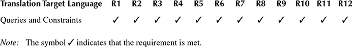
From this requirements analysis, summarized in Table 12.5, we conclude that the query and constraint approach proposed is a step toward a more comprehensive consistency management approach for UML models. However, more work is required to implement tools to automate the approach and experiment with the effective scalability of such tools by testing them on large industrial-scale system models.
12.5 Summary and Outlook
UML is a widely accepted language that can be used at different stages of the development process. In fact, while the current state of the art provides profiles that support real-time systems modeling, some issues in ensuring consistency, defining semantics, understanding models, and integrating models of large-scale systems still hamper the applicability of UML to this domain. To address these shortcomings, we discussed the consistency problem and steps toward a comprehensive solution for it in more detail.
From our analysis of the various techniques to address consistency management in UML, we infer that, even if it is theoretically possible to manage consistency in UML, the problem has not been solved yet completely. Most of the problems in dealing with consistency, and in general in developing analysis tools and techniques for UML arise from the size and complexity of the UML metamodel and from the lack of a comprehensive semantics definition. Consistency of models and correctness of analysis and synthesis tools are key requirements for modeling real-time systems—hence, research into increased consistency provides significant leverage for improved quality for this systems class.
We proposed a solution for consistency checking of UML based on the definition of an abstract model of the application domain that we want to target and a translation of the UML metamodel to this abstract domain. We also defined two theorems that apply to our consistency checking solution: the first enables checking consistency on subsets of system models, the second enables using SAT solvers for LTL to automate consistency checking. Although we believe the solution we proposed to be a significant step in the right direction, to make its use practical, providing a tool that supports automatic translation and detection of inconsistencies is important future work.
Acknowledgments
This work was partially supported by the National Science Foundation within projects CCF-0702791 and CNS-0963702, as well as by funds from the California Institute for Telecommunications and Information Technology (Calit2) at the University of California, San Diego, CA. We are grateful to Barry Demchak and the anonymous reviewers for insightful comments.
References
1. Giese, H., G. Karsai, E. Lee, B. Rumpe, and B. Schätz. 2011. Model-Based Engineering of Embedded Real-Time Systems. Lecture Notes in Computer Science, Vol. 6100. Berlin/ Heidelberg: Springer.
2. Object Management Group. 2010. “Unified Modeling Language (OMG UML), Infrastructure, Version 2.3.” formal/2010-05-03, OMG.
3. Object Management Group. 2010. “Unified Modeling Language (OMG UML), Superstructure, Version 2.3.” formal/2010-05-05, OMG.
4. Sprinkle, J., B. Rumpe, H. Vangheluwe, and G. Karsai. 2011. “Metamodelling—State of the Art and Research Challenges.” In Model-Based Engineering of Embedded Real-Time Systems, edited by H. Giese, G. Karsai, E. Lee, B. Rumpe, and B. Schätz, 57–76. Lecture Notes in Computer Science, Vol. 6100. Berlin/Heidelberg: Springer.
5. Object Management Group. 2009. “UML Profile for MARTE: Modeling and Analysis of Real-Time Embedded Systems, Version 1.0.” formal/2009-11-02, OMG.
6. Warmer, J., and A. Kleppe. 1998. The Object Constraint Language: Precise Modeling with UML. Wokingham, U.K.: Addison-Wesley.
7. Batory, D., D. Benavides, and A. Ruiz-Cortes. 2006. “Automated Analysis of Feature Models: Challenges Ahead.” Commun ACM 49 (12): 45–7.
8. Object Management Group. 2003. “Model Driven Architecture (MDA), Version 1.0.1.” omg/03-06-01, OMG.
9. Winter, V., F. Kordon, and M. Lemoine. 2004. “The BART Case Study.” In Formal Methods for Embedded Distributed Systems, edited by F. Kordon, and M. Lemoine, 3–22. New York, NY: Springer US.
10. Finkelstein, A. C. W., D. Gabbay, A. Hunter, J. Kramer, and B. Nuseibeh. 1994. “Inconsistency Handling in Multiperspective Specifications.” IEEE Transactions on Software Engineering 20 (8): 569–78.
11. Easterbrook, S., and B. Nuseibeh. 1996. “Using ViewPoints for Inconsistency Management.” Software Engineering Journal 11 (1): 31–43.
12. Easterbrook, S. 1996. “Learning from Inconsistency.” In Proceedings of the Eighth International Workshop on Software Specification and Design, March 22–23, 1996, pp. 136–40. Schloss Velen, Germany. Washington, DC, USA: IEEE Computer Society.
13. Easterbrook, S., J. Callahan and V. Wiels. 1998. “V&V through Inconsistency Tracking and Analysis.” In Proceedings of the Ninth International Workshop on Software Specification and Design, April 16–18, 1998, pp. 43–9. Mie, Japan, Washington, DC: IEEE Computer Society.
14. Evans, E. 2004. Domain-Driven Design: Tackling Complexity in the Heart of Software, 560. Wokingham, U.K.: Addison-Wesley.
15. Hongyuan, W., F. Tie, Z. Jiachen, and Z. Ke. 2005. “Consistency Check between Behaviour Models.” In IEEE International Symposium on Communications and Information Technology, pp. 486–9.
16. Engels, G., J. M. Küster, R. Heckel, and L. Groenewegen. 2001. “A Methodology for Specifying and Analyzing Consistency of Object-Oriented Behavioral Models.” SIGSOFT Software Engineering Notes 26 (5): 186–95.
17. Malgouyres, H., and Motet, G. 2006. “A UML Model Consistency Verification Approach Based on Meta-Modeling Formalization.” In Proceedings of the 2006 ACM Symposium on Applied Computing, April 23–27, 2006, pp. 1804–9. Dijon, France, New York: ACM.
18. Van Der Straeten, R., T. Mens, J. Simmonds, and V. Jonckers. 2003. “Using Description Logic to Maintain Consistency between UML Models.” In “UML” 2003—The Unified Modeling Language, 2003, pp. 326–340.
19. Van Der Straeten, R., and D’Hondt, M. 2006. “Model Refactorings through Rule-Based Inconsistency Resolution.” In Proceedings of the 2006 ACM Symposium on Applied Computing, April 23–27, 2006, pp. 1210–7. Dijon, France, New York: ACM.
20. Sabetzadeh, M., and S. Easterbrook. 2006. “View Merging in the Presence of Incompleteness and Inconsistency.” Requirements Engineering 11 (3): 174–93. New York: Springer-Verlag.
21. Nentwich, C., W. Emmerich, A. Finkelstein, and E. Ellmer. 2003. “Flexible Consistency Checking.” ACM Transaction Software Engineering Methodology 12 (1): 28–63. New York: ACM.
22. Engels, G., J. H. Hausmann, R. Heckel, and S. Sauer. 2002. “Testing the Consistency of Dynamic UML Diagrams.” In Proceedings of the 6th International Conference on Integrated Design and Process Technology (IDPT), Pasadena, California, June 23–28, 2002.
23. Egyed, A. 2007. “Fixing Inconsistencies in UML Design Models.” In Proceedings of the 29th International Conference on Software Engineering, May 20–26, 2007, pp. 292–301. Los Alamitos, CA: Minneapolis, IEEE Computer Society.
24. Egyed, A. 2007. “UML/Analyzer: A Tool for the Instant Consistency Checking of UML Models.” In Proceedings of the 29th International Conference on Software Engineering, pp. 793–6.
25. Object Management Group. 2007. “MOF 2.0/XMI Mapping, Version 2.1.1.” formal/2007-12-01, OMG.
26. Egyed, A. 2006. “Instant Consistency Checking for the UML.” In Proceedings of the 28th International Conference on Software Engineering, May 20–28, 2006, pp. 381–90. Shanghai, China: ACM Press.
27. “A Formal Semantics for UML.” 2006. Workshop at MoDELS. May 12–19, 2001. Toronto, Ontario, Canada. Washington, DC: IEEE Computer Society.
28. Krüger, I. H., and M. Menarini. 2007. “Queries and Constraints: A Comprehensive Semantic Model for UML2.” In Models in Software Engineering, edited by T. Kühne, 327–8. Lecture Notes in Computer Science, Vol. 4364. Berlin/Heidelberg: Springer.
29. Broy, M., M. Cengarle, and B. Rumpe. 2006. Towards a System Model for UML. The Structural Data Model. Technical Report TUM-I0612. Munich, Germany: Munich University of Technology.
30. Broy, M., M. Cengarle, and B. Rumpe. 2007. Towards a System Model for UML. Part 2. The Control Model. Technical Report TUM-I0710. Munich, Germany: Munich University of Technology.
31. Broy, M., M. Cengarle, and B. Rumpe. 2007. Towards a System Model for UML. Part 3. The State Machine Model. Technical Report TUM-I0711. Munich, Germany: Munich University of Technology.
32. Broy, M., and K. Stølen. 2001. Specification and Development of Interactive Systems: Focus on Streams, Interfaces, and Refinement. Berlin/Heidelberg: Springer.
33. Easterbrook, S., and M. Chechik. 2001. “A Framework for Multi-Valued Reasoning Over Inconsistent Viewpoints.” In Proceedings of the 23rd International Conference on Software Engineering, May 12–19, 2001, pp. 411–20. Toronto, Ontario, Canada. Washington, DC: IEEE Computer Society.
34. Inverardi, P., H. Muccini, and P. Pelliccione. 2001. “Automated Check of Architectural Models Consistency Using SPIN.” In Proceedings of the 16th Annual International Conference on Automated Software Engineering, November 26–29, 2001, pp. 346–9. San Diego, California, edited by H. Muccini. Washington, DC: IEEE Computer Society.
35. Ossami, D., J. Jacquot, and J. Souquières. 2005. “Consistency in UML and B Multi-View Specifications.” Integrated Formal Methods 3771: 386–405.
36. Engels, G., R. Heckel, and J. M. Küster. 2001. “Rule-Based Specification of Behavioral Consistency Based on the UML Meta-Model.” In Proceedings of the 4th International Conference on UML 2001—The Unified Modeling Language. Modeling Languages, Concepts, and Tools. October 1–5, Toronto, ON, Canada, pp. 272–86.
37. Paige, R. F., P. J. Brooke, and J. S. Ostroff. 2007. “Metamodel-Based Model Conformance and Multiview Consistency Checking.” ACM Transaction Software Engineering Methodology 16 (3): 11.
38. Clarke, E., and E. Emerson. 1982. “Design and Synthesis of Synchronization Skeletons Using Branching Time Temporal Logic.” In Logics of Programs, edited by D. Kozen, 52–71. Lecture Notes in Computer Science, Vol. 131. Berlin/Heidelberg: Springer.
39. Holzmann, G. J. 2004. The SPIN Model Checker: Primer and Reference Manual, p. 608. Wokingham, U.K.: Addison-Wesley Professional.
40. Milner, R. 1982. A Calculus of Communicating Systems, April 1, 1985, p. 256. Secaucus, NJ: Springer-Verlag New York, Inc.
41. Abrial, J. R. 1996. The B-Book: Assigning Programs to Meanings. Cambridge, MA: Cambridge University Press.
42. Hoare, C. A. R. 1985. Communicating Sequential Processes. Upper Saddle River, NJ: Prentice Hall.
43. Ingolf Heiko Krüger. 2000. “Distributed System Design with Message Sequence Charts.” PhD dissertation. Fakultät für Informatik, Technischen Universität München.
44. Pnueli, A. 1977. “The Temporal Logic of Programs.” In Proceedings of the 18th Annual Symposium on Foundations of Computer Science (FOCS 1977), October 31– November 2, 1977. pp. 46–57. Long Beach, CA: IEEE Computer Society.
45. Goranko, V., A. Kyrilov, and D. Shkatov. 2010. “Tableau Tool for Testing Satisfiability in LTL: Implementation and Experimental Analysis.” Electronic Notes in Theoretical Computer Science 262: 113–25. Elsevier Science Publishers B. V.
46. Rozier, K. Y., and M. Y. Vardi. 2007. “LTL Satisfiability Checking.” In Proceedings of the 14th International SPIN Conference on Model Checking Software, pp. 149–67. Berlin/Heidelberg: Springer-Verlag.