7 Progressive Simulation-Based Design for Networked Real-Time Embedded Systems
Xiaolin Hu and Ehsan Azarnasab
CONTENTS
7.2 PSBD for Networked Real-Time Embedded Systems
7.2.2 Bifurcated Design Process for Networked Real-Time Embedded Systems
7.4.1 Design Procedure and Implementation Environment
7.1 Introduction
Simulation has long been used to support design and analysis of complex engineering systems. Fast simulations allow designers to flexibly experiment with and analyze different design solutions without implementing the systems in hardware. Real-time simulations support designers to test the real-time features of a system that interacts with the physical world and/or other hardware components. The latter is especially useful for designing real-time embedded systems, such as mobile devices, manufacturing automation sensors/actuators, and the networked software-defined radio (SDR) system presented in this chapter. Design and implementation of these systems have been influenced by the increasing demand of new products and the recent advances in technologies. The complexity and multidisciplinary nature of these systems make analytical modeling and analysis infeasible. However, system engineers must assess a design before proceeding with implementation of an expensive solution. Although traditional modeling and simulation can help in this goal, its applicability has been limited because of the gap between simulation models and implementation in hardware.
One type of real-time simulation is hardware-in-the-loop (HIL) simulation, which is an advanced technique frequently used in embedded systems’ development [1,2]. A HIL simulation refers to a system in which parts of a pure simulation have been replaced with actual hardware. This is based on the observation that once hardware is added to the loop, unmodeled characteristics can be investigated and controls can be further refined. HIL is typically aimed at developing a single module in a larger system. Although it is a useful technique that can greatly support an engineering design, it does not offer a general methodology that can scale to more complex systems. Systematic design processes and methodologies are necessary for designing complex systems that are characterized as large scale and networked with tight couplings between software and hardware. Motivated by this need, we developed a progressive simulation-based design (PSBD) methodology that goes beyond HIL simulation by gradually adding more hardware to the simulated system in a progressive manner and improving the co-simulated model in each step before continuing [3]. The design process of PSBD starts from all models being simulated on computers, proceeds by bringing real system components into the simulation to replace their virtual counterparts (models), and ends when all components are in their deployed form and the final system is tested in a physical environment. Throughout this process, model continuity is emphasized and the simulation model is continually updated whenever new design details are revealed. Several distributed robotic systems have been developed following the principles of the PSBD methodology [4, 5 and 6].
This chapter presents the PSBD for networked real-time embedded systems. We give an overview of the PSBD methodology and show a bifurcated design process that implements PSBD for individual embedded devices and the networked embedded system. We then apply the PSBD methodology to the design of a networked SDR system. SDR technology refers to a radio communication system capable of transmitting and receiving different modulated signals across a large frequency spectrum using software programmable hardware [7]. Major components of a SDR board include a digital signal processor (DSP), field-programmable- gate-array (FPGA), and radio frequency (RF) front end that facilitates wireless communication among the nodes. A DSP or a conventional central processor unit computes baseband signal processing and implements the MAC layer for networking. An FPGA is used for fast parallel processing of incoming data and down-sampling the result to a lower sample rate suitable for baseband processing. SDR provides modem designers a great opportunity to build complex modems by programming in software the previously hardware components of the radio. This replacement of hardware by software is in line with the model continuity approach of PSBD, as the individual system components are code modules to be developed and tested along the design process. The advantage of PSBD becomes more explicit when multiple SDR nodes should collaborate to form a network. Hence, the interaction of many complex subsystems should be engineered for best performance of the entire system. We show how PSBD is applied to a single cognitive modem and a cognitive radio (CR) network. This chapter extends the previous work on the PSBD methodology [3] and the case study example on SDR [8]. We aim to show that PSBD is an effective methodology that can be applied to a wide range of networked real-time embedded systems and engineering applications.
The modeling and simulation environment that supports this work is based on Discrete Event System Specification (DEVS) [9,10]. DEVS is a formalism derived from generic dynamic systems theory and has well-defined concepts of coupling of components, hierarchical, modular model construction, and object-oriented substrate supporting repository reuse. DEVS models time explicitly. This makes it convenient to study timeliness, which is an essential property of real-time systems. The DEVSJAVA environment [11] is used in this work to support fast and real-time simulations in the design process. More information about the DEVS formalism can be found in Zeigler et al. [9]. Applying DEVS-based modeling and simulation to system design has been researched in previous work. For example, a DEVS-based model-driven approach for developing embedded real-time systems was presented in Wainer and coworkers [12,13] to improve the quality of a design and to reduce the need for expensive testing cycle. A methodology for developing hybrid hardware/ software systems was presented in Glinsky and Wainer [14], where techniques were developed to enable transition from the simulated models to the actual hardware counterparts and to allow developing models with different levels of abstraction. A stepwise model refinement approach was proposed in Schulz and Rozenblit [15] to support real-time embedded system development. In Kim et al. [16], a DEVS-based unified framework was presented for developing real-time software systems, in which logical analysis, performance evaluation, and implementation can be performed. Our work on PSBD emphasizes a systematic process that progressively transitions a design from models to system realization. We note that although the DEVS simulation environment is used in this work, the presented PSBD methodology is general and can be realized using other modeling and simulation environments.
7.2 PSBD for Networked Real-Time Embedded Systems
This section provides an overview of the PSBD methodology [3] and develops a bifurcated design process for networked real-time embedded systems.
7.2.1 PSBD Overview
PSBD views simulation as the driving force for designing and testing engineering systems. It provides a design process that explicitly focuses on systematic transitions from simulation models to system realization. As shown in Figure 7.1, the design process consists of three stages, each of which is characterized by the types of entities (virtual or physical) that are involved. The first stage is conventional simulation (in fast simulation mode), where simulation is carried out using all models. A major task of this stage is to develop the system model based on available knowledge and assumptions about the hardware and operating environment of the physical system. Often discrepancies between simulation models and physical system components exist. These discrepancies cause the models to comprise behavior different from the system behavior. To reveal such design discrepancies, the next stage of the design process is virtual environment simulation (in real-time simulation mode), where simulation-based study is carried out in a virtual testing environment using combined models and physical system components. This stage brings simulation-based study one step closer to a realization by including physical system components into the simulation. The goal is to use physical system components to reveal overlooked design details, and thus help designers improve the control models/algorithms under development. The final stage is physical system experiment, where the physical system is tested in the target operating environment.
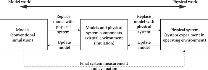
FIGURE 7.1 Progressive simulation-based design methodology.
Along this design process, the PSBD methodology emphasizes two parallel activities in a progressive manner: replace models with physical system components and update models. As the design moves forward, physical system components are incrementally brought into the simulation to replace models. Simulations with these physical system components allow designers to validate their design assumptions and to reveal new design details. Such information is fed back to the previous stages to update the models if necessary. The updated model will then be used for follow-on design and test. This activity of model update allows designers to maintain a coherent model of the system under development. Thus, at the end of the design, not only the system is realized and tested, but also a system model that faithfully represents the system is developed. This system model can support final system measurement and evaluation (shown by the dashed line in Figure 7.1) and serve other purposes such as system maintenance and future development. It is important to note that each design stage is a dynamically evolving process by itself. For example, during the conventional simulation stage, it is common for designers to start from high level models and then refine them to more detailed models. Similarly, the virtual environment simulation stage that involves combined models and physical system components typically includes multiple phases too, for example, to start with replacing one physical system component first and then gradually add more.
Two important features of the PSBD methodology are model continuity and virtual environment simulation that supports simulation-based test with combined virtual and physical system components. Model continuity refers to the ability to transition as much as possible of a model specification through the stages of a development process [17]. For real-time embedded systems, we restrict model continuity to the models (software components) that implement the real-time control of the system. This means the control models of a real-time embedded system are designed, analyzed, and tested by simulation methods and then smoothly transitioned from simulation to hardware execution in the physical environment (see Hu et al. [4] and Azarnasab [6] for more details). To support model continuity, it is necessary to develop system models and run simulation-based tests in a systematic way. A modular design and well-defined interfaces are necessary to ensure the control models work with physical and simulated hardware in the same way at different stages of the design process [4,6]. The virtual environment simulation provides a virtual testing environment by using combined physical and virtual system components. It bridges the gap between conventional simulations that use all models and physical system experiments that use all physical system components. To support the virtual environment, simulation techniques must be developed that synchronize the physical and virtual system components. This includes allowing the physical and virtual components to “sense” each others’ existence (see Hu and Zeigler [18] for an example of how physical and virtual robots are synchronized with each other). Meanwhile, time synchronization is also important. Since hardware components are included in the simulation-based study, real-time simulations are necessary to support the virtual testing environment.
7.2.2 Bifurcated Design Process for Networked Real-Time Embedded Systems
Networked real-time embedded systems are characterized by a network of embedded devices interacting with each other and the tight couplings between software and hardware of those devices. Each of these devices is referred to as a node in this chapter. When commercial-off-the-shelf (COTS) nodes are not used, design of networked real-time embedded systems must design both the individual nodes and the networked system as a whole. Within this context, the PSBD methodology described above is elaborated to include a bifurcated design process as shown in Figure 7.2. The bifurcated design process explicitly differentiates the design of a single node (the bottom route in Figure 7.2) and the design of the networked system (the top route in Figure 7.2). The former mainly concerns designing the different functional modules, such as sensing, modulation/demodulation, and channel coding, of the embedded device. The latter focuses on how the multiple nodes work together as a whole, including designing and improving the communication protocols and the cooperative strategies among the nodes. Despite the different design focuses, both designs follow the PSBD process that starts from models and gradually adds more physical system components.
In Figure 7.2, the models are shown as white boxes; the physical system components are shown as grey boxes. The design starts and bifurcates into two routes: the design of a single node and the design of the networked system. For designing a single node, the first step is to model the functional modules of the embedded device and simulate how they work together to fulfill the functionality of the device. Then hardware components are brought into the design and HIL simulations are conducted to test how well the designed modules and algorithmic code work with the hardware. This proceeds in a stepwise fashion as more and more hardware components are included. Consider the CR (described later) as an example, first the channel sensing mechanism is implemented on the FPGA and DSP hardware, then the data transmission and data reception components are included, and finally the reporting mechanism is implemented. We use a signal generator and signal analyzer to help to test the developed components before a working node is complete. Eventually, all the code modules are implemented in the hardware and the embedded node is tested with all hardware components.
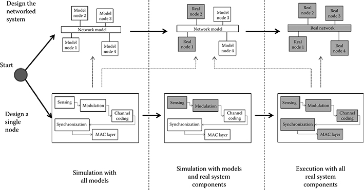
FIGURE 7.2 A bifurcated design process for networked real-time embedded system.
When designing the networked system, the first step is to develop individual node models and a model of the communicating network. The individual node model can reuse the model from designing the single node (as indicated by the dotted arrow in Figure 7.2). Alternatively, a different node model at a higher abstraction level (e.g., without including all the details of the devices’ functional modules) can be used. Simulations with these models allow designers to test the networked system in the model world. The next step is to gradually include physical device nodes into the simulation-based study to conduct virtual environment simulations. The physical device nodes are either the ones from the single node design or COTS nodes. This continues until the entire system is realized and all designed nodes are tested in a physical network. It is important to note that the bifurcated design process provides a systematic view for designing general networked embedded systems. For a specific application, the design process can be tailored (e.g., some design stages are elaborated while others are omitted) to fit the specific design needs of the application. In Section 7.4, we provide an example of designing a CR system by starting from the design of a single radio modem and then proceeding to the design of a CR network. The single radio modem is also designed in progressive manner, where different functional modules are gradually implemented/tested in the hardware while other modules are provided by simulation models.
PSBD brings several advantages when designing complex networked engineering systems. Some of them are shared by the traditional HIL simulation. For example, it brings simulation-based study one step closer to the reality to provide useful information for designers. It also increases confidence by the designer about how the final system will operate. However, PSBD goes beyond that by emphasizing a systematic design process that gradually adds more physical system components to replace simulation models. The virtual environment simulation provides the flexibility for experimenting with a design in a virtual testing environment. It allows designers to use several, instead of all, physical nodes to carry out a system-wide test of a networked system. This is especially useful for large-scale networked real-time embedded systems whose complexity and scale severely limit experimentations in a physical environment using all physical nodes. As the scale of these systems increases, so does their design and test complexity. It is the intent of PSBD to systematically handle such design complexity in a progressive manner.
7.3 Background on CR Design
The scarcity of unallocated frequency spectrum and the necessity for different radios to coexist in the shared unlicensed bands highlight the importance of the next generation of radios with dynamic spectrum access. Traditionally, spectrum is assigned to legacy devices, also called primary users (PUs). However, licensed frequency bands are rarely used everywhere [19,20] and over time lead to spectrum holes in time and space. To address this underutilization Federal Communications Commission has loosened the regulation to allow secondary users (SUs) to share some previously dedicated bands subject to minimal interference with legacy devices of the band [21]. Based on this definition of coexistence, SUs attempt to dynamically fill the spectrum holes over time and space [20], thus forming a CR [22]. For example, when a TV station (which is a PU of some frequency band) is not broadcasting or is in a location far from any TV broadcasting, SUs can instead use the spectrum in an opportunistic fashion. Spectrum access for first responders in a disaster scenario, where many wireless devices are active, is another application of CR [23].
A typical CR network consists of multiple SUs that coexist with PUs of a shared spectrum. PUs have priority access to the spectrum over SUs, that is, SUs should relinquish the spectrum when PUs begin transmission. The SU network should be designed to utilize more of the available bandwidth subject to minimum interference with the PUs. The hidden terminal problem (when a node is visible from a wireless access point (AP) but not from other nodes communicating with the AP) should be solved to minimize interference. For this purpose, SUs should form a CR network to sense the presence of active PUs and dynamically adapt to a suitable frequency, resulting in little or no interference with PUs. They collaboratively sense the spectrum and decide which part of the spectrum is available to them. Collaborative sensing involves signaling/reporting through a (possibly narrow band) control/ reporting channel. To maximize the bandwidth efficiency of the SU network while minimizing interference with PUs, this signaling should be done in a reliable manner and in a minimum span of time. In addition to this requirement, it is desirable to have a system operating among radios with different modulations and protocols and supplied by various vendors. Coexistence and interoperability are two major design goals for a CR network. SDR technology best satisfies the required flexibility of CR, and thus is often used to implement CR network [24,25]. A SU that is realized on a SDR hardware board is called a cognitive modem. Design of a CR network must design the individual cognitive modems and the CR network as a whole.
The complexity of designing an individual cognitive modem is due to the many functional components and their complicated mutual interactions. These components can be implemented in parallel to expedite the manufacturing process. Parallelism can be achieved by simulating the entire system for a functional component that is being developed. Here the simulation closes the loop of system integration and provides a regression testing environment. In addition, as is common in system engineering design, not all hardware is available at the beginning of the project. Therefore, simulation is necessary to start the design with the partial hardware that is available. The rest of the functional components are provided by simulation. In our project, at first we received only one baseband module of SDR, capable of processing only the DSP algorithms such as polyphase implementation of a filterbank for channel sensing. We tested our sensing algorithm using a simulated fading channel and optimized it to some extent. The high dynamic range of filterbank sensing better detects low power PU; thus, it is less likely to interfere with legacy users. By the time we developed our fixed-point sensing method, we received one RF front end and applied sensing on a physical wireless channel to replace the previously simulated channel. The complexity of designing the CR network lies in the potentially large number of SUs and PUs that influence each other. By simulating the rest of the network before more hardware was available, we were able to test a CR network of many SUs when only one SDR board was available. Below we present how the progressive-based simulation design was applied to the design of both individual cognitive modems and the CR network. In this project, the code running on the hardware board was compiled by the Code Composer Studio (optimization level). The compiled code was then uploaded to the Small Form Factor (SFF) SDR [26] hardware platform provided by Lyrtech and Texas Instruments.
7.4 PSBD of the CR Network
The PSBD methodology described above has been applied to the design of a CR network. We describe the overall design procedure, present the design of a single cognitive modem, followed by the design of a CR network, and show some experiment results.
7.4.1 Design Procedure and Implementation Environment
The design started from a single cognitive modem and then proceeded to the CR network. As part of the simulation-based testing environment, simulated PUs generated data traffic based on a model of the application layer for realistic PUs on particular frequency channels. Depending on the channel, the traffic model can be a constant bit rate (CBR), a burst data, or a Poisson process. For example, Internet traffic is often modeled as bursts of data transfer, CBR is a good model for TDMA networks such as voice traffic, and Poisson process is a generic model of data arrival. Simulated SUs not only generate data traffic, but also are responsible for handling signaling packets over a control channel of the network.
In the first stage of PSBD, we implemented a single transceiver (transmitter and receiver radio). First, MATLAB® was used for conventional modeling and simulation of a generic transceiver modem and a generic channel. The goal was to find out the parameters to achieve the required bit error rate (BER) of the radio system. Second, one SDR board and simulation models formed a co-simulation carried out in DEVSJAVA [11]. In this stage, the signal processing and data acquisition components of the transceiver were substituted by physical hardware components (such as DSP and FPGA components) on the board. The remaining components were DEVSJAVA models. To support reuse, the DEVSJAVA models reused the corresponding MATLAB functions in the first stage. The MATLAB Builder™ for Java can build Java libraries from MATLAB functions and have them ready to use in DEVSJAVA. In our project, the MATLAB m-files developed for MATLAB simulation of the channel, some MATLAB visualization methods, and also the MEX files (that interfaced the SDR board) were compiled to Java methods and used inside the DEVSJAVA simulation. The embedded MATLAB code inside DEVSJAVA helped in generating precise communication-specific models such as traffic and random fading of multipath channel. In this way, we were able to avoid reimplementing and testing mathematical methods and could focus on higher level network modeling in DEVSJAVA. The integration of DEVS and MATLAB models decoupled the design of CR network model from the underlying complicated mathematical functions.
While MATLAB is good at mathematical modeling, it is not straightforward to model the event-driven nature of interconnected components. On the other hand, DEVSJAVA can naturally support network modeling and, thus, was used to model the network of CR nodes. After an initial cognitive modem was implemented (as one SU), the next step was to design the CR network. At first, a complete simulation of a CR network with SUs and PUs was developed in DEVSJAVA. The conventional simulation simulated the activities of channel assignments for SUs and PUs. An SU acting as a Secondary Base (SB) station model received the sensing information from all SUs and compiled channel state information. In our system, we had distributed sensing to avoid the hidden node problem as much as possible. A vector signal generator emulated the traffic of simulated PUs and simulated SUs on the physical channel. In modeling the network, CR nodes were modeled by DEVS atomic models and the network was modeled as a DEVS coupled model. The scheduled messages passing between the DEVS atomic models carried packets with different lengths. Based on the propagation rules, the channel model rescheduled the messages to the receiver. Note that DEVS modeling is homomorphic. This means the CR node could be modeled as a coupled model itself including its functional component models. The hierarchical model construction of DEVS helped in modeling the internal interactions of subsystems of a single cognitive modem and the interactions of multiple cognitive modems in a network. During the course of PSBD, we replaced two of the simulated SUs with physical CRs to carry out a virtual environment test. In the setup of the virtual environment simulation, the physical nodes used filterbanks to detect the presence of the PUs and sent the sensing information to the SB, which was simulated on a PC. In this way, we were able to develop the network and to carry out system-wide test without having to wait for all hardware to become available. Below we describe the two design routes in detail.
7.4.2 Design of a Single Cognitive Modem
Based on the PSBD methodology, a model of a modem was first developed at an abstraction level according to the design goal. This model included all the functional modules of the cognitive modem. First, we started from a conventional simulation of the cognitive modem in a simulated environment. In this example, the environment was defined by the frequencies in use and a channel model. It dynamically changed as a result of PU or SU transmission or channel fading. The model was simulated in Simulink® to test for the required BER [24].
Figure 7.3 shows the model of the cognitive modem, which includes physical layer and MAC layer modules. The MAC layer module is the core of this model. The cognition algorithm inside the MAC layer module is responsible for compiling the spectral information sensed by the filterbank sensing module to provide a utility function. This utility function is used to determine the channels that should be assigned and the duration for which those channels are valid. The filterbank sensing [7,23] module is applied directly on the channel to detect the power spectral density (PSD) and thus the active PUs. The synchronization module detects the incoming packets while correcting the residual carrier offset before passing data to an equalizer to compensate for the effect of channel on data. The communication channel in the simulation is considered as an additive white Gaussian (AWGN) model. Conventional simulations based on this model allow us to test the cognitive algorithm inside the MAC layer and the functionality of the physical layer.
The conventional simulation, however, is insufficient to design and test the features that are influenced by the implementing hardware. For example, tuning algorithm/ protocol parameters to achieve optimal synchronization results depends on the real-time properties of the hardware that cannot be predetermined without employing the actual hardware. In our design, the MAC layer protocol is decentralized and consisted of three phases. In the sensing phase, all the nodes sense the channel. In the reporting phase, all the nodes communicate their cognition results over a control channel. The cognition algorithm uses these reports to assign channels. In the channel usage phase, all the nodes start using the assigned channels. The purpose of the reporting period is to maximize cognition accuracy by sharing the cognition knowledge of individual SUs. Note that only the transmission time contributes to the effective bandwidth, and therefore, the time spent in reporting and sensing should be minimized. Since sensing takes a constant duration, an important task in designing the cognitive modem is to optimize the MAC layer so that reporting time is minimized [27]. Also we should note that the transmission time cannot last for a very long time, because a PU may return and thus SUs must release the occupied channels to the PUs. The time that SUs are permitted to transmit continuously without sensing is thus determined by a statistical model of PU arrivals in the bands of interest. To better design these features, the next stage is to include physical hardware components into the simulation for virtual environment simulation.
FIGURE 7.3 Simulation model of a single cognitive modem. It includes sensing, transmission, and reception.
It is challenging to decide to what extent simulation-assisted design should be involved and to what level the system should be decomposed. A single cognitive modem comprises many individual radio modules, each of which is a candidate for virtual environment simulation along with other simulated objects and the environment. Figure 7.4 shows how virtual environment simulation is carried out in designing a single modem. In this figure, one SDR board is used. The simulation runs on a single PC, while the SDR board (running implemented components) is connected to that PC via an Ethernet cable. Since sensing the channel is the most critical part of the CR, we implement this component in the earliest stage as shown in the rightmost section of Figure 7.4. We implement filterbanks sensing in DSP of the board. To test the sensing module, we emulate PU traffic on different frequency bands using a wide-band vector signal generator. The transmitted traffic of PU by the signal generator is a multiband waveform generated using a MATLAB script. In this stage, we adjust some design parameters such as analog-to-digital converter gains, frequency axis margins, and power threshold of PU detection. After sensing is implemented, other components such as modulation/demodulation and channel coding are implemented in the order depicted in the figure.
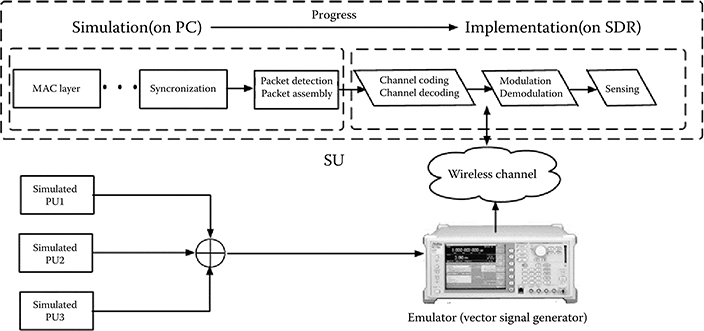
FIGURE 7.4 Progressive simulation-based design of a single cognitive modem. The implementation starts from the sensing module and progressively more of the simulated models (left dotted box) are implemented (right dotted box). The rectangles are Discrete Event System Specification models simulated on PC, and parallelograms are implemented modules on the software-defined radio board.
7.4.3 Design of a CR Network
After the cognitive modem is implemented, we design the CR network using the developed cognitive modem. Similar to the design of a single modem, we start from conventional simulation of the cognitive network using the model of cognitive modem developed in the previous stage. In our design, first we consider a centralized network where some SUs were assigned to act as SB stations. This approach leads to a global common plane architecture for signaling and control to avoid the hidden node problem for PUs. This is essential in any CR network to avoid interfering with existing PUs. SB is in charge of synchronization and channel assignment. It compiles the channel state information based on sensing results of SUs and uses this knowledge to rank different parts of the spectrum and blacklist some active channels. After the role of each CR node is assigned, we model the cognitive network, which includes multiple PU and SU models, a SB model, and a Channel model that simulates the features of the wireless channel. Conventional simulations using this network model allows us to test if the SUs can successfully detect nonused bands and to dynamically use them without interfering with the PUs. A sample simulation result is provided in Section 7.4.4
The next stage is to introduce physical cognitive modems (SUs) in the simulation. The virtual environment simulation includes physical SUs, physical PUs, simulated SUs, simulated PUs, and simulated channels (used only between simulated SUs). Figure 7.5 shows the setup of a virtual environment simulation and the interconnections among simulated, emulated, and physical components. In Figure 7.5, two physical SUs (Lyrtech SFF SDR boards, denoted as Real SU1 and Real SU2) and one physical PU (two-way radio, denoted as Real PU1) are used. The simulated SUs and PUs are emulated using a vector signal generator to generate spectral energy on the bands of the simulated agents. Therefore, the physical SUs would see the channel as if the simulated users exist. To test the cognitive modem against the generic PU channel usage pattern, the traffic of the PU (being simulated) is known and programmed in the PU model. The emulation of the PUs and SUs is necessary to test the sensing mechanism of physical SUs. The simulated SUs use the simulated channel and simulated traffic directly from the simulated PUs. The simulated channel is also used between two simulated SUs when transmitting a packet. A fading channel and different exponential PU traffic (with various mean for each channel) is implemented in MATLAB and compiled to be invoked by DEVSJAVA. Note that the emulator is considered as part of the testing environment and is not included in the system model.
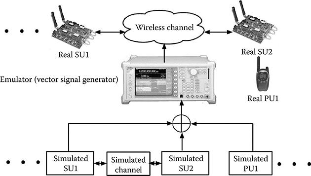
FIGURE 7.5 Virtual environment simulation of a cognitive radio network. The rectangles are Discrete Event System Specification models.
To carry out virtual environment simulation, it is important to set up the environment so the physical and simulated nodes can “sense” each other’s existence. For example, when a physical SU uses a band of the channel, the simulated SUs must know the band has been occupied (by the physical SU). The reverse is true too. Thus, a two-way communication is necessary between the physical SUs and the PC that hosts the simulated SUs. In our system, as shown in Figure 7.5, the emulator conveys the simulated environment and broadcasts the information sensed by the physical SUs. To support the communication from a physical SU to the PC, an Ethernet cable (not shown in Figure 7.5) is used to connect the physical SU with the PC. During the “report” stage of the MAC protocol, a physical SU sends its information to the PC through the Ethernet cable. Note that the Ethernet cable is not necessary in testing the physical system, in which case wireless communication is used. To synchronize the physical and simulated SUs (meaning to allow the physical and simulated SUs to know each other’s existence) in a systematic way, each physical SU has a “shadow model” on the PC. This is similar to the robot-in-the-loop simulation [4–6], where each physical robot has a counterpart robot model in the simulation environment on the PC. The shadow model is responsible for receiving report information from the real SU and then passes that information to the Channel model similar as how other simulated SUs do.
Figure 7.6 shows a DEVS model of a CR network including two PUs, two SUs, and one SB in the virtual environment simulation. One of the SUs (SU2), the two PUs (PU1 and PU2), and also the SB station are simulated on the host PC. The other SU (SU1) has a hardware implementation and thus is executed using the co-simulation engine. The SU1 shown in Figure 7.6 is the shadow model of the real SU1. Using the message passing mechanism of DEVS between the models, in which messages are external events, and also exploiting the time-triggered message generation inside the modeled nodes, which are internal events, the simulation of the network is implemented. We use immediate messages for passing parameters between the models, while time scheduled messages are used to pass the data-carrying binary signals. For the simulated nodes, after a transmitter sends a packet of data, the Channel model passes the binary signal, along with the carrier frequency and other required parameters to MATLAB code that simulates a complete transmitter, channel, and receiver. The MATLAB code for the transmitter includes source coding, baseband modulation, upsampling and RF modulation, downsampling, etc. For the receiver, the necessary functions are also developed in MATLAB and the data (that may include error) are passed to the node in DEVS. The physical cognitive modem SU1 relies on its embedded software for data transmission, and the virtual environment simulation engine handles the interface between the shadow model SU1 and the physical SU1.
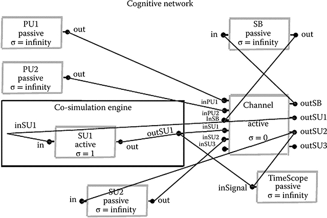
FIGURE 7.6 A cognitive network Discrete Event System Specification model with two primary users (PUs), two secondary users (SUs), and one Secondary Base (SB) station. SU1 is implemented on a small form factor software-defined radio board and emulated along with the other nodes.
7.4.4 Experiment Results
Based on the PSBD methodology, we designed and implemented three cognitive SUs as follows. After initial simulation of one SU in MATLAB, we agreed on certain technical parameters. Then inside DEVSJAVA along with a generic simulation of one PU, we improved our SDR implementation of one SU along with its model. In the next step, we added one more SDR-based physical SU and more PU nodes along with one simulated SB to our network [24,28]. The simulated SB was in charge of transmitting channel assignment over the reporting channel. It combined the individual sensing result of the SU and assigned channels to them upon their request.
Figure 7.7 shows the result of a conventional simulation with all-simulated SUs and PUs. In this simulation, 2 SUs and 16 PUs were used. A flat fading wireless channel was used for simulation with white noise, and filterbanks were used for sensing. The simulation demonstrates how a SU can dynamically detect and change its band to avoid interfering with a PU. As shown in the top part of Figure 7.7, initially PU6 was not present (its power was below the noise temperature) and SU1 was using its band. Then as shown in the bottom part of Figure 7.7, as soon as PU6 returned, SU1 dynamically found another unused band that was less likely to have a PU any time soon as described in Amini et al. [24] and changed to the new band. In this simulation, SU2 used a band that no other PU was using. Thus, SU2 did not have to change its band.
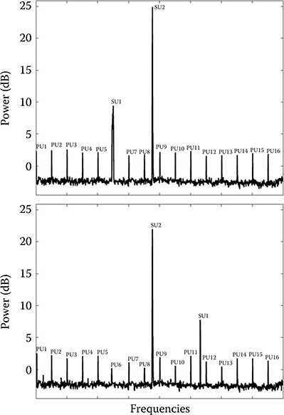
FIGURE 7.7 Simulation results using all models.
Figure 7.8 shows the result of a virtual environment simulation that included one physical SU and 12 simulated PUs. In this experiment, we implemented three sensing methods, including filterbank, Fast Fourier Transform (FFT), and FFT with Hanning, and compared them. The collected data was the PSD sensed from a densely populated spectrum for 256 subcarriers in an experiment. This figure shows that SB reassigned a new frequency band to the only SU when PU3 was detected in the adjacent frequency of the previous carrier (the dotted vertical line in the top figure). As a result, the SU changed to a new band (shown by the vertical dotted line in the bottom figure). The top and bottom figures show before and after the PU3 detection, respectively. The continuous transmission of voice during this action also proved the success of the frequency hopping. This experiment shows that the cognition modem was capable of locating a less active band in the spectrum where more than 10 active PUs were transmitting. In addition, as shown in this figure, the FFT sensing could not detect two PUs on the right-hand side of the frequency spectrum, while the developed filterbank sensing could easily find them.
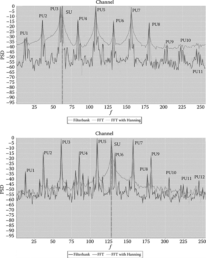
FIGURE 7.8 Simulation results using one physical secondary user (SU) among many primary users (PUs).
7.5 Conclusions
We present a PSBD methodology for designing networked real-time embedded systems. The methodology includes a bifurcated design process that implements PSBD for designing both individual embedded devices and the networked embedded system as a whole. We apply this methodology to the development of a CR network. A single cognitive modem was first developed in a progressive manner and then the CR network was built in the same fashion. During this process, the MAC layer model was fine-tuned to increase the data rate of CR, while minimizing interference with PUs. Experimental results show that the designed CR system was able to respond dynamically to the changing environment to avoid active PUs on a real-time basis, while continuing the functionality of a wireless radio. The system was presented successfully at the 2007 Smart Radio Challenge [28] held by the SDR forum. This case study example shows the effectiveness of the PSBD methodology for developing complex networked real-time embedded systems.
Gradually including physical system components into a design to replace the simulation models should consider factors such as hardware availability, cost, speed, and required accuracy for a certain application. Strategies can be developed in the future to provide guidelines for including hardware in a stepwise fashion in the PSBD. Characterizing the types of systems that can take advantage of the PSBD methodology is another interesting topic asking for further research.
References
1. Li, L., T. Pearce, and G. Wainer. 2003. “Interfacing Real-Time DEVS Models with a DSP Platform.” In Proceedings of the Industrial Simulation Symposium, Valencia, Spain.
2. Upton, J. 1998. Boeing 777 (AirlinerTech Series). 2nd ed. Voyageur Press (MN), vol. 2.
3. Hu, X. 2010. “From Virtual to Real: A Progressive Simulation-Based Design Framework,” Discrete-Event Modeling and Simulation: Theory and Applications, edited by G. A. Wainer, P. J. Mosterman, Boca Raton, FL: CRC Press.
4. Hu, X., N. Ganapathy, and B. P. Zeigler. 2005. “Robots in the Loop: Supporting an Incremental Simulation-Based Design Process”. In IEEE International Conference on Systems, Man, and Cybernetics, Hawaii.
5. Azarnasab, E. and X. Hu. 2007. “An Integrated Multi-Robot Test Bed to Support Incremental Simulation-Based Design.” In Proceedings of the IEEE International Conference on System of Systems Engineering, San Antonio, TX.
6. Azarnasab, E. 2007. “Robot-in-the-Loop Simulation to Support Multi-Robot System Development: A Dynamic Team Formation Example.” Master’s thesis, Georgia State University, Department of Computer Science, Atlanta, GA.
7. Farhang-Boroujeny, B. 2008. Signal Processing Techniques for Software Radios. Morrisville, North Carolina: Lulu Publishing House.
8. Azarnasab, E., X. Hu, P. Amini, and B. Farhang-Boroujeny. 2008. “Progressive Simulation-Based Design: A Case Study Example on Software Defined Radio”. In Proceedings of the 2008 IEEE Conference on Automation Science and Engineering (IEEE-CASE 2008), Washington DC.
9. Zeigler, B., H. Praehofer, and T. Kim. 2000. Theory of Modeling and Simulation. 2nd ed. New York: Academic Press.
10. Zhang, Ming, Bernard Zeigler, Xiaolin Hu. 2012.“A Formalized Approach for Design of Real-Time Distributed Computer System.” In Real-Time Simulation Technologies: Principles, Methodologies, and Applications, edited by K. Popovici, P. J. Mosterman, CRC Press, ISBN 9781439846650.
11. Zeigler B. P. and H. S. Sarjoughian. 2005. Introduction to DEVS Modeling and Simulation with JAVA: Developing Component-Based Simulation Models, Resources http://www.acims.arizona.edu/SOFTWARE/devsjava_licensed/CBMSManuscript.zip (last accessed April, 2012) .
12. Wainer, G. A. and E. Glinsky. 2004. “Model-Based Development of Embedded Systems with RT-CD++.” In Proceedings of the WIP Session, IEEE Real-Time and Embedded Technology and Applications Symposium, Toronto, ON, Canada.
13. Wainer, G. A., E. Glinsky, and P. MacSween. 2005. A Model-Driven Technique for Development of Embedded Systems Based on the DEVS Formalism. Springer-Verlag.
14. Glinsky, E. and G. A. Wainer. 2004. “Modeling and Simulation of Hardware/Software Systems with CD++.” In Proceedings of the 36th Conference on Winter Simulation, Washington DC.
15. Schulz, S. and J. W. Rozenblit. 2002. “Refinement of Model Specifications in Embedded Systems Design.” In Proceedings of the 2002 IEEE Conference on Engineering of Computer-Based Systems, 159–66. Sweden: Lund.
16. Kim, T. G., S. M. Cho, and W. B. Lee. 2001. “DEVS Framework for Systems Development: Unified Specification for Logical Analysis, Performance Evaluation and Implementation.” In Discrete Event Modeling and Simulation Technologies: A Tapestry of Systems and AI-Based Theories and Methodologies. New York, NY: Springer-Verlag New York, Inc.
17. Hu, X. and B. P. Zeigler. 2005. “Model Continuity in the Design of Dynamic Distributed Real-Time Systems.” IEEE Transactions On Systems, Man And Cybernetics—Part A: Systems And Humans, 35 (6), 867–78.
18. Hu, X. and B. P. Zeigler. 2005. “A Simulation-Based Virtual Environment to Study Cooperative Robotic Systems.” Integrated Computer-Aided Engineering (ICAE) 12 (4), 353–67.
19. Brodersen, R., A. Wolisz, D. Cabric, S. Mishra, and D. Willkomm. 2004. CORVUS: A Cognitive Radio Approach for Usage of Virtual Unlicensed Spectrum, White paper, Berkeley, Technical Report. http://bwrc.eecs.berkeley.edu/Research/MCMA/CR_White_paper_final1.pdf (last accessed April, 2012).
20. Shankar, N., C. Cordeiro, and K. Challapali. 2005. “Spectrum Agile Radios: Utilization and Sensing Architectures.” In First IEEE International Symposium on New Frontiers in Dynamic Spectrum Access Networks (DySPAN), 160–9. Baltimore, Maryland.
21. FCC 2002. Spectrum Policy Task Force. ET Docket 02-135.
22. Haykin, S. 2005. “Cognitive Radio: Brain-Empowered Wireless Communications.” IEEE Journal on Selected Areas in Communications.
23. Amini, P., R. Kempter, and B. Farhang-Boroujeny. 2006. “A Comparison of Alternative Filterbank Multicarrier Methods in Cognitive Radio Systems.” In Software Defined Radio Technical Conference, Orlando, FL.
24. Amini, P., E. Azarnasab, S. Akoum, X. Mao, H. I. Rao, and B. Farhang-Boroujeny. 2007. “Implementation of a Cognitive Radio Modem.” In Software Defined Radio Technical Conference, Denver, CO.
25. Su, H. and X. Zhang. 2008. “Cross-Layer Based Opportunistic MAC Protocols for QoS Provisionings over Cognitive Radio Wireless Networks.” In IEEE Journal on Selected Areas in Communications, 26 (1), 118–29.
26. “Lyrtech SFF SDR Development Platform Technical Specs.” 2007. Lyrtech Inc., Technical Report. http://www.lyrtech.com/publications/sff_sdr_dev_platform_en.pdf, (last accessed February, 2007).
27. Azarnasab, E., R.-R. Chen, K. H. Teo, Z. Tao, and B. Farhang-Boroujeny. 2009. “Medium Access Control Signaling for Reliable Spectrum Agile Radios.” In IEEE Global Telecommunications Conference (GLOBECOM), ISSN: 1930-529X. 1–5, Honolulu, Hawaii.
28. Azarnasab, E., P. Amini, and B. Farhang-Boroujeny. 2007. “Hardware in the Loop: A Development Strategy for Software Radio.” In Software Defined Radio Technical Conference, Denver, CO.