
21 Specification and Simulation of Automotive Functionality Using AUTOSAR
Marco Di Natale
CONTENTS
21.2.6 AUTOSAR Tools and the Role of Tools
21.3 Use of AUTOSAR Models for Simulation And Analysis
21.3.1 Use of AUTOSAR in the Development Process
21.3.2 Simulation at the VFB (and Behavior) Level
21.3.3 Simulation at the RTE Level
21.3.4 Simulation at the BSW Level: From ECU-Level Simulation to Full Architecture Modeling
21.4 Model-To-Model Integration and Translation: From Simulink® to AUTOSAR and From AUTOSAR to Simulink®
21.5 Simulation, Timing Analysis, and Code Generation: Consistency Issues and Model Alignment
21.1 Introduction
The Automotive Open System Architecture (AUTOSAR) development partnership, which includes several carmakers or original equipment manufacturers (OEMs), car electronics (Tier 1) suppliers, and tool and software vendors, has been created to develop an open industry standard for automotive software architectures. The AUTOSAR standardization effort spans across all software levels, from device drivers to the operating system, the communication abstraction layers, the network stacks, and also the specification of application-level components.
The current version of the standard includes several specifications, which can be roughly classified into
A standard specification for the definition of application software components (SWCs), their interfaces, and an environment for their cooperation at the functional level.
A standard for the definition of the cooperation of component behaviors, including the definition of the events that are relevant for executing the runnables of components, which are defined as procedures executed in reaction to events.
A reference software platform architecture, encapsulating the basic software (BSW) (operating system and device drivers included) and providing a middleware layer for the execution of components and their interactions (including communication and exchange of signals and events).
A standard format for the (coarse grain) description of distributed hardware architectures, the description of the mapping of runnables to tasks, and the mapping of those onto the execution architecture.
A metamodel formalizing all the above.
In addition, AUTOSAR defines a development model (or, more appropriately, major steps and cornerstones in the development process) with automated support by tools and a common interchange format, based on XML, for model information at all stages in the process.
The AUTOSAR project has focused on the concepts of location independence, interface standardization, and code portability. The initial purpose was to enable the transition from Federated Architectures to Integrated Architectures. In a Federated Architecture, suppliers provide a node or electronic control unit (ECU) to be integrated in a network for each major functionality, which caused a proliferation of nodes and complex dependencies on network messages. In an Integrated Architecture, OEMs provide the specification of SWCs to suppliers, who are responsible for their development according to a standardized interface. OEMs can then integrate SWCs on an architecture platform of their choice. This type of portability and modularity requires the definition of a standard for SWCs, which includes the definition of their interfaces and a standard application program interface (API) for interacting with the software abstracting the physical platform. Hence, the AUTOSAR model has been strongly oriented to the representation of typical interactions among software packages and its semantics is strongly oriented to the modeling of cooperating procedures, rather than the representation of a formal model of computation (MoC) with a mathematical underpinning.
Later, with the evolution of the standard, the goal has become more ambitious and AUTOSAR is becoming a candidate for full-fledged system-level modeling, including capabilities for simulation and (worst-case) timing analysis or possibly even other types of analysis (such as reliability) that are required on system-level models.
The need for better control over the emergent behavior, the opportunity for analysis (by simulation or other formal method), and the need for controlling integration of heterogeneous models (for example Simulink® subsystems [1]) led the consortium to the specification of the AUTOSAR metamodel, which however, is still far from being based on a formal MoC.
To give an example, the notion of time and timed events was only introduced in the latest (4.0) release of the standard [2], with the goal of enabling worst-case timing analysis of response times at the level of specifications. Unfortunately, it appears that the timed event model is at best cumbersone if the purpose is, for example, to build a common discrete-time base for a system-wide AUTOSAR model integrating synchronous reactive (SR) models as subsystems. In addition, currently there is no tool support for the use of timed events.
With respect to the goal of simulation, AUTOSAR is clearly oriented toward the following: the simulation of functionality considering the structure of the SWCs and their actual code implementation; the implications of the mapping of the runnables to the elements of the execution architecture; and of scheduling issues and other platform-related delays, such as communication latency and operating system or device-driver delays. As such, AUTOSAR models and tools can be used for both hardware-in-the-loop (HIL) or software-in-the loop simulations (see also the classification in the chapter at Ref. [3]) and can be performed in real time or in logical time.
AUTOSAR is not suited to the representation of continuous-time systems. Therefore, its use in a model-in-the-loop framework will require integration with other tools (such as Simulink). These tools either provide the plant model and cooperate in a cosimulation environment or produce the code implementations for the models of the missing (continuous-time) systems. AUTOSAR models are a better fit to simulate the controller part. However, the lack of support for a detailed behavioral model makes their use unlikely in the early stages. AUTOSAR runnables are intended to be simple entry points for a code procedure. Even when the runnable behavior is available as a dataflow or as a state machine (or other type of model), either a cosimulation environment linking other tools (such as Simulink) to an AUTOSAR simulation engine or (more likely) the actual code implementation is required.
In conclusion, with respect to the framework outlined in the previous chapter, an AUTOSAR model can be simulated either right before or right after the availability of a real-time executable. The underlying model is a discrete event model based on the available framework of the run-time environment (RTE) events (described in the following sections). An AUTOSAR model can be constructed for the simulation of discrete-time systems by leveraging timed events (although creating a global-time framework is not necessarily an easy task, given that periodic timed events are local to each component).
Also, with respect to the task of model verification, the lack of a clear semantics with respect to time makes any type of formal verification of correctness in model-to-model transformations difficult or even impossible altogether.
We provide first a short introduction to AUTOSAR and its main concepts. Next, we discuss issues related to the possibility of using an AUTOSAR description of the system for simulating its behavior at increasing levels of accuracy with respect to the model of the execution platform. Finally, issues related to the necessity of maintaining a consistent view of the models that are used for simulation, timing analysis, and code generation are discussed.
21.2 Introduction to AUTOSAR
AUTOSAR was created to develop an open industry standard with a common software infrastructure based on standardized interfaces for SWC specification and integration at different layers. In agreement with the move toward an integrated architecture, the AUTOSAR goal is to enable the definition of SWCs that can execute independently from their placement in a complex, distributed platform.
The AUTOSAR architecture has three major domains. In the first, at the level of the Virtual Functional Bus (VFB), the system is described as a collection of application SWCs, cooperating over ports in a purely functional architecture (top part of Figure 21.1, which outlines the tool-assisted match between the AUTOSAR functional model and the execution platform). The VFB consists of the set of logical connections linking the interfaces of the cooperating SWCs. AUTOSAR separates communication from computation and synchronization. The component interface is defined as a collection of ports, and the execution of the procedures of a component is represented by a set of runnables, activated in response to events and defined in a behavior level.
At runtime, the set of SWCs is executed on a standard software abstraction layer. This layer is automatically generated according to the specification of the (possibly distributed) execution platform supporting the computations and according to the specifications of the VFB layer and the behaviors of the components. The software layer between the platform and the realization of the SWCs using the standard API is called RTE (run-time environment). The RTE is the runtime implementation of the VFB and has the responsibility of implementing the virtual communication occurring over the component ports redirecting it to a concrete communication protocol. The concrete implementation differs according to the task mapping and the ECU allocation of the communicating runnables. In addition, the RTE generates events resulting from the component interactions and is responsible for the generation of periodic events.
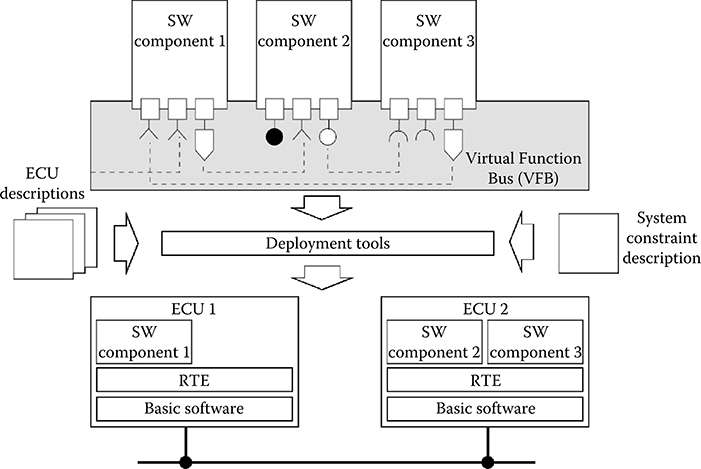
FIGURE 21.1 The AUTOSAR functional model and a deployment onto a distributed architecture.
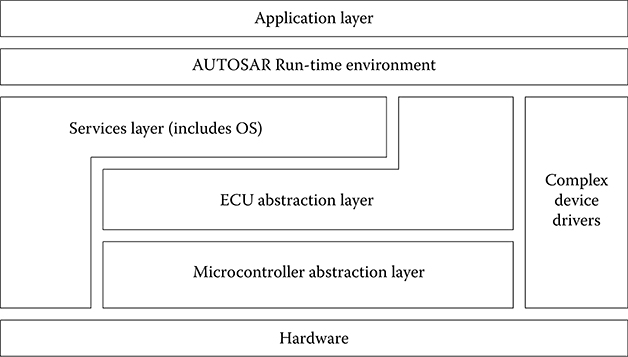
FIGURE 21.2 The AUTOSAR standard software platform.
The RTE, in turn, runs on a standardized architecture of additional abstraction layers, device drivers, and operating system functions, which is collectively referred to as BSW (an outline of the standard SW platform is in Figure 21.2).
The third element of the specification is the AUTOSAR process itself, or better the definition of a basic workflow that connects the main development stages, with the expected results and the definition of the tools to be used in each stage.
21.2.1 VFB Level
The first level for the definition of an AUTOSAR system is the Functional Model, where SWCs encapsulating sets of system-level functions are connected and cooperate over a VFB (Figure 21.1). Later, they are bound to an execution platform consisting of ECUs connected by communication buses. AUTOSAR components may be defined hierarchically. At the bottom of the hierarchy, components are “atomic,” meaning that each instance is assigned to one ECU (cannot be distributed).
In AUTOSAR, a component defines its required and provided interface through ports, which are the only means to interact with other components. Ports may provide or require access to data or services. A port defining a provided point of access is defined as a P-Port, and a required port is called R-Port. An Interface, attached to each port, may be of type client/server, defining the signatures of the operations that are invoked or provided, or of type sender/receiver, defining a model of the data structures that are written or read. The formal description of the interface is in the software component template, an XML file, which includes the formal specification of the data types and the description of the communication behavior, as specified by attributes.
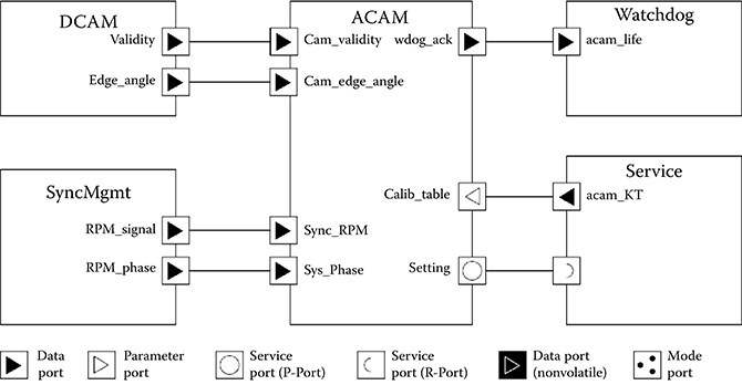
FIGURE 21.3 AUTOSAR components and ports.
Those attributes define (among others) the length of the queues for the data ports and the behavior of receivers (blocking, nonblocking, etc.) and senders (send cyclic, etc.). Figure 21.3 shows an example of AUTOSAR components interacting over sender/receiver ports and client/server ports.
The port syntax identifies several types of data ports: regular data type, parameter ports, and nonvolatile ports. Furthermore, the language syntax identifies special ports for the definition of mode switches and also provides for a distinction between application ports and ports that connect application components to AUTOSAR services.
21.2.2 Behavioral Level
In AUTOSAR, the behavior of atomic SWCs is represented by a set of runnable entities (runnables for short) that are in essence entry points of procedures or, as stated in the standardization documents, atomic schedulable units (sequential segments of code, to be executed under the control of a scheduler), communicating with each other over the component ports. AUTOSAR provides several mechanisms for runnables to access the data items in the ports for sender/receiver communication and the services of client/server communication ports. In particular, access to ports of type Send/Receive can be implicit or explicit. In the case of an explicit access, it is the job of the developer to insert calls to the standard RTE API functions for reading from and writing into ports inside the runnables. If a port is accessed in an implicit way by a runnable, then the port contents are copied from the port automatically by the RTE before starting the runnable code (for receive ports) or written at the end of the runnable execution (for sender ports). The activation model, the communication among runnables, and the synchronization in the execution of runnables (local and remote) is specified in a middle-level RTE layer.
21.2.3 RTE Level
The run-time environment (RTE) is the runtime implementation of the VFB. The RTE is local to each ECU. It is a complex layer that must provide location independence in the request of services and data communication among components. The RTE also takes care of the management and forwarding of events to runnables (for triggering their execution or releasing them from wait points). In practice, in the case of local communication, service requests are simply remapped to local function calls. In the case of remote services, the RTE forwards the call to a stub that performs marshalling of parameters in a message, selects the appropriate communication network and the corresponding device driver, transmits the message, and waits for the reply message. When the reply message arrives, the RTE extracts the returned value and closes the remote service request by returning to the caller and generating (if requested) the appropriate event.
The available RTE events are the following:
Timing Event triggering periodical execution of runnables.
DataReceivedEvent upon reception of a sender/receiver communication.
OperationInvokedEvent for the invocation of client/server service.
DataSendCompleteEvent upon sending a sender/receiver communication.
Each runnable must be associated with at least one RTE event, defining its activation. The scope of each RTE event is limited to the component. For example, two periodic events with the same period activating runnables on different components are not guaranteed to be synchronous. Actually, their relative phase is unspecified unless explicitly modeled by using synchronization components (typically at the BSW level). In case a runnable is activated by more than one event, it must be reentrant or the developer must take care of protecting its internal state variables. A WaitPoint can be used to block a runnable while waiting for an event. Runnables that may block during their execution are called type 2, as opposed to the others, defined as type 1 (this definition impacts the selection of the operating system scheduler and of the scheduling policies). For instance, for an operation defined as part of a component interface, the behavior specifies which runnable is activated as a consequence of the operation invocation event.
The only possible definition of an AUTOSAR MoC emerges from the composition of the behavior options that are attached to each interface and runnable specifications, with no guarantee of consistency. The concept of time and time-related events, which is necessary for the formal definition of an MoC, has only appeared in release 4.0 of the standard. The time model is briefly addressed and discussed in Section 21.2.5.
Finally, there is the description of components/runnables at the implementation level. The language for the description of the internal behavior of runnables is not part of AUTOSAR. AUTOSAR does not require a model-based development flow: a component may be handwritten or generated from a model. For the definition of the models of the runnables, it relies on external tools such as Simulink and ASCET, which brings the issue of the composition of heterogeneous models. The lowest (most concrete) level of description specifies a reference to the code files implementing the runnables of the components and the resource consumption of SWCs. This resource requirements model includes the worst-case execution time of runnables, for which a special section is reserved in the implementation description of the runnables.
AUTOSAR defines the methodology and tool support to build a concrete system of ECUs. This includes the configuration and generation of the runtime environment (RTE) and the BSW (including the real-time operating system) on each ECU. The generation of the RTE and BSW layer is the responsibility of the deployment tools, which define the mapping of the function to the architecture and the generation of code based on the model of the execution platform, defined (in XML format) by the ECU description files.
Finally, the definition and realization of components is not limited to the application level. Designers can define runnables and components at the level of the BSW as well, with less restrictive rules. These runnables and components are included in the code automatically generated by the deployment tools and can be directly activated by events generated at the operating system level (interrupt handlers, counters, and alarms in AUTOSAR).
21.2.4 AUTOSAR Process
AUTOSAR requires a common technical approach for selected steps in the development process, from the system-level configuration to the generation of the executables for each ECU. The AUTOSAR Methodology (a graphical representation is in Figure 21.4) is the description of these activities, with their inputs and outputs. The AUTOSAR Methodology is formally not a true process description since it does not prescribe the order in which the activities should be performed, neither the actors involved.
The first step is the creation of the System Configuration Input, which defines the SWCs, the hardware execution platform, and the system constraints that apply to the mapping of the components onto the ECUs. The format for the formal description is defined in a standard XML schema and includes the following templates.
Software Components: Each SWC is described in terms of its ports and interfaces, including the data types and the port attributes.
ECU Resources: Each ECU requires specifications regarding the processor unit(s), the available memory, and the available peripheral devices, including sensors and actuators.
System Constraints: Regarding the mapping of the signals into bus messages as well as the mapping of the component runnables into tasks and the allocation of tasks into the ECUs.
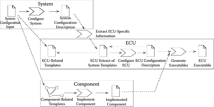
FIGURE 21.4 The AUTOSAR process.
The System Configuration Input includes or references various constraints. These constraints are very simple and mostly consist of forced or forbidden mapping configurations. In reality, the template allows for the definition of estimates on the availability of resources on ECUs, thereby providing less intuitive constraints to mapping configurations.
The Configure System activity has the responsibility to map all the SWCs to ECUs and also to define the system communication matrix. This matrix describes the message frames exchanged over the system networks, that is, the mapping of the signal information (the data exchanged over ports) into the frames. Deriving such a mapping is extremely complex and consists of a system optimization problem, in which system metrics of interest, including performance and possibly reliability, extensibility, and composability should be maximized considering constraints on resources and timing requirements [4,5]. In the mind of the AUTOSAR developers, this synthesis and optimization process should be assisted by a set of tools, defined as System Configuration. The output of this activity is the System Configuration Description including system information (e.g., bus mapping and topology) and the mapping of SWCs to ECUs.
Further steps must be performed for each ECU in the system. The activity denoted as Extract ECU-Specific Information extracts the information from the System Configuration Description for a specific ECU, thereby generating the ECU Extract of System Configuration. This step is rather simple since it consists of a projection of the elements of the System Configuration Description that are allocated to a specific ECU.
At the ECU level, the system configuration stage is mirrored by the Configure ECU activity, where the RTE and the BSW modules are configured for each ECU. This includes the definition of the task model (the assignment of runnables to tasks) and the configuration of the scheduler and of the BSW components (driver included). The result of the activity is included in the ECU Configuration Description. The configuration is based on the information extracted from the ECU Extract of System Configuration, the definition of the Available SWC Implementations, and the BSW Module Description. The latter contains the vendor-specific information for the ECU configuration.
This activity defines the detailed scheduling information, the configuration of the communication module, the operating system, and other AUTOSAR services. Moreover, this is the time when an implementation must be provided for each atomic SWC. In contrast to the extraction of ECU-specific information, the configuration activity is actually a complex design synthesis and optimization step.
In Build Executable (last step), an executable is generated based on the configuration of the ECU. This step typically involves generating code (e.g., for the RTE and the BSW), compiling code (compiling generated code or compiling SWCs available as source code), and linking everything together into an executable.
Parallel to these steps are several steps performed for every application SWC (to be integrated later into the system), including the generation of the component’s API and the implementation of the component’s functionality.
The initial work in this context starts with providing the necessary parts of the SWC description. That means at least the Component Internal Behavior Description as part of the SWC-related templates has to be filled in. The internal behavior describes the scheduling-relevant aspects of a component, that is, the runnable entities and the events they respond to. Furthermore, the behavior specifies how a component (or more precisely which runnable) responds to events like receiving data elements. However, it does not describe the detailed functional behavior of the component, which is only filled in later, when the Component Implementation (typically the C sources) is provided, together with additional implementation-specific information and information about the further build process steps (e.g., compiler settings, optimizations, etc.).
21.2.5 AUTOSAR Timing Model
Starting from version 4.0, AUTOSAR includes a Specification of Timing Extensions [6]: a language overlaid on top of the existing AUTOSAR concepts with the primary purpose of enabling the definition of timing contracts and the (worst-case) schedulability analysis of the timing behavior of a system. Unfortunately, the keywords “simulation,” “model of computation,” or “model-to-model transformation” never appear among the list of the requirements for the timing model, which is indeed lacking with respect to the needs of a formal semantics for simulation and verification.
With respect to the AUTOSAR process, the timing specification extends the AUTOSAR metamodel, without necessitating a separate template. Also, the extension is introduced without the indication of any additional process steps. Hence, the description of the previous subsection remains fundamentally unchanged.
In the specification of timing extensions for AUTOSAR, the event is the basic entity. It is used to refer to an observable behavior within a system (e.g., the activation of a RunnableEntity and the transmission of a frame) at a point in time. The AUTOSAR timed event is formally derived from a generic abstract concept defined as TimedDescriptionEvent. Unfortunately, timed events are not specializations of RTE events, but define a partly independent structure of timing annotations and constraints. As a consequence, it becomes problematic to maintain and enforce the consistency between the RTE events defining the behavior semantics (i.e., the activation and the synchronization among runnables) and the timed events providing time attributes and constraints that apply to the behaviors. The description of the timing elements follows the organization of the AUTOSAR-level views (Figure 21.5).
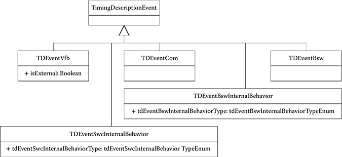
FIGURE 21.5 Types of events by modeling level.
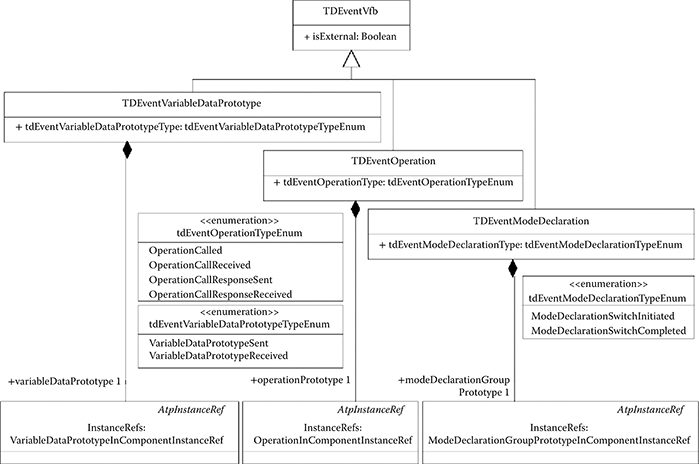
FIGURE 21.6 Timed events defined for the virtual functional bus level.
Timing events and constraints can be applied to a VFB-level view. Functional end-to-end timing constraints (including possibly the physical sensors and actuators) can be captured in this view. Of course, the VFB view is independent of the platform design and of the allocation of the execution resources. Therefore, the analysis does not include any timing issues from resource scheduling, nor the description of platform overheads. Also, the internal behavior of components is not considered. In conclusion, the constraints that can be defined and analyzed are execution intervals, as opposed to deadlines, defined between events on component ports. As shown in Figure 21.6, the timed events allowed at this level mirror the corresponding RTE events on ports (such as, for example, the time at which data is sent or received, an operation called, or an operation call received). When adding the internal behavior description, timed events can refer to the activation, start, and termination (see Figure 21.7) of the execution of RunnableEntities. This specification still mostly applies to the definition, and possibly verification, of end-to-end deadline constraints.
After the BSW and ECU generation stage, more information is available on the resources of the execution platform, and the allocation of runnables to tasks and of tasks to ECUs. Also, the model now includes the specification of schedulers and the composition of the message frames. Therefore, the events that are defined at these levels also apply to tasks and message frames. This is the level where schedulability analysis can be performed and also the level where timed events could be leveraged to simulate the impact of platform-dependent delays.
In general, at all levels, the occurrence of a timing event can be described by an Event Triggering Constraint. AUTOSAR offers four basic types of event triggering constraints as described in Figure 21.8: periodic events, sporadic events, which are characterized by a minimum interarrival time, and bursty events, in which the specification defines periodic bursts occurring with a given period, and the composition of each burst in terms of number of events and minimum interarrival time. Finally, streams determined by the position in time of each event and fully arbitrary patterns complete the available categories.
In addition, the extension defines constraints and properties that apply to pairs or sets of events (their relations). One notable example of a relation among events is the event chain, with which the concept of end-to-end timing constraint is associated (Figure 21.9).
For the purposes of simulation, an important requirement is the possibility of defining causality dependencies, that is, to enforce a partial order of execution among the system actions and the possibility of enforcing synchronization among the actions. Before the timing extensions, expressing a causal dependency and synchronizing the events triggering the execution of runnables was extremely difficult if even possible at all (an example of this difficulty is provided in the following section dealing with model-to-model transformations).
Unfortunately, the new timing extensions only provide a partial solution. Causality constraints can indeed be expressed by an Execution Order Constraint, which is used to express the functional dependency between ExecutableEntities (runnables) and to restrict their order of execution at runtime. The AUTOSAR Synchronization Timing Constraint, however, is not intended to be used to define a consistent time base for timed events and, in turn, for the system behavior. The definition of a set of system-wide synchronized timed events could have allowed the AUTOSAR modeling of discrete-time systems and the translation of synchronous models in AUTOSAR. However, the original purpose of the specification is different and synchronization constraints do not apply to sets of individual events but to event chains, with the possibility of synchronizing the initial stimulus or the final response times. The motivation for the current definition of timed events is to reduce the pessimism in the worst-case analysis of end-to-end response times. Indeed, the synchronization constraint is intended to be defined together with a tolerance, indicating a true specification constraint on the runtime behavior of complex chains of reactions rather than (for example) a method for enforcing a discrete-time framework.
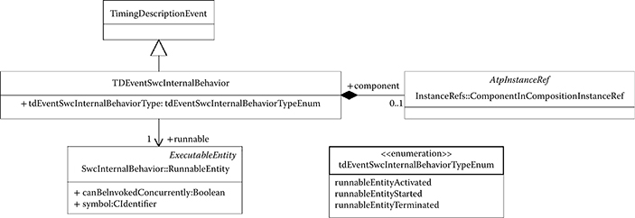
FIGURE 21.7 Timed events that apply to the behavior description.
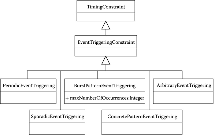
FIGURE 21.8 Metamodel of timing events in AUTOSAR 4.0.
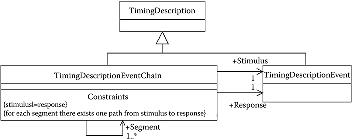
FIGURE 21.9 Metamodel of timing event chains in AUTOSAR 4.0.
Another set of constraints can be used for the purpose of synchronization: the offset constraints. These constraints are somewhat more suited to the synchronization of events since they explicitly target individual events rather than chains. However, an offset always refers to a single pair of events (a source and a target), which once again makes its use cumbersome for a system-wide synchronization of reactions.
In conclusion, it is worth noting that version 4.0 of the standard is very recent and still not supported by commercial tools. The hope is that future evolve and become more suited to the goals of simulation and allow for better integration (meaning on formal grounds) of heterogeneous models.
21.2.6 AUTOSAR Tools and the Role of Tools
From the description of the AUTOSAR process, it is very clear how the use of tools is recommended or even mandatory in several activities, such as the code generation and configuration stages. Indeed, there are currently several AUTOSAR tools available on the market. In addition, the AUTOSAR consortium members realized that there is a common or core module that is required by all tool providers. This core module includes the functions for the management of the metamodel and the enforcement of its rules in the construction of a model, the representation of the model in memory, the generation and parsing of the input and output files at each stage of the AUTOSAR process in the standard ARXML format, and basic capabilities for model editing.
The consortium members launched a common initiative to create an open project (Artop, an open source project, although open for contribution and use by the consortium members only [7]) that leverages the metamodeling and modeling features of the Eclipse platform [8] to develop a common foundation that could be exploited by all AUTOSAR tools developers, vendors, and users. The code of the Artop project is available to the members of the consortium that can contribute to its development and use it in the form they see fit, either directly (in the case of OEMs and Tier 1 suppliers) or, more likely, as a common starting point for the development of commercial tools in the case of tool vendors. Artop does not have simulation and analysis capabilities and does not include code generators or the mapping synthesis capability for matching a functional model to an execution platform. These components are intended to be developed as custom extensions by tool vendors.
Currently, tool vendors tend to specialize in the different process activities that are requested by the standard. Several companies offer tools for the design of AUTOSAR models. Examples of products in this area are SystemDesk by dSPACE [9], DaVinci by Vector [10], and AUTOSAR Builder by Geensoft [11]. These tools include RTE generators, but not the configuration of the BSW. Also, they offer (somewhat limited) simulation capabilities (mostly at the VFB and behavior level as discussed in more detail in the following section).
Other companies provide products, such as Tresos from Elektrobit [12], specialized in the stages of BSW generation and configuration, including the operating system.
In general, the mapping of the functional model into the execution platform is quite far from being a synthesis process supported by an optimization engine. Currently, tools typically provide a default configuration of the task model and require a complete user specification with respect to the mapping of the tasks onto the ECUs.
Limited support for AUTOSAR is also offered by other modeling tools, including, for example, Simulink. The support does not include full model-to-model transformation capabilities (not surprisingly, given the sematics distance between the two models), but focuses on these areas:
Integration of code generated from a Simulink model with the RTE generated by AUTOSAR tools
Generation of a component or runnable specification by wrapping a ( virtual) Simulink subsystem to allow its inclusion in an AUTOSAR model
Importing an AUTOSAR component specification into Simulink by
automatically generating an equivalent subsystem interface model
21.3 Use of AUTOSAR Models for Simulation And Analysis
Before going into the technical details on the use of AUTOSAR models for simulation and the discussion of the issues related to model-to-model transformations, it is important to recall what information is necessary for building an AUTOSAR model and at what stage in the development process an AUTOSAR description of the system should be available. In other words, is the AUTOSAR description the first and authoritative description of the system functions or is it produced later in the development based on some other models or outputs? Also, we should ask what could be the contribution of simulation performed on an AUTOSAR model to the understanding of the system dynamics. This question is relative to the possible advantages and outputs of a system-level simulation (or analysis of other types, including timing and reliability) performed on AUTOSAR models. That is, what can an AUTOSAR model tell us that cannot be obtained in another way?
An initial short answer could be the following: given that AUTOSAR is fundamentally an empty container for functional behavior descriptions and given its limitations in the modeling of continuous-time systems, it is probably (as of now) not a realistic starting point for system-level modeling and analysis, but rather a valuable intermediate formalism that allows a better evaluation of the impact of the software design and coding and of the software–hardware execution platform on the performance of the controls and the other application functions.
21.3.1 Use of AUTOSAR in the Development Process
A possible use of the AUTOSAR formalism and tools in a development process is therefore the following:
The system functionality, including the system controls, are modeled in a suitable language (e.g., Simulink), together with the plant model, and validated by simulation with logical execution time assumptions. In case the controller (re)uses AUTOSAR SWCs, possibly imported in Simulink.
The execution platform for the system is selected and modeled in an AUTOSAR environment.
The functional model is translated into a corresponding AUTOSAR set of components, some functionality is possibly realized by reusing existing component models, and the virtual AUTOSAR model resulting from the composition is mapped onto the execution architecture according to the AUTOSAR process.
The result of the mapping stage, performed by the AUTOSAR tools, is the definition of the communication matrix, the task model, and the configuration of the RTE and BSW levels. This definition now allows the simulation of the system functions considering platform-related issues, including the simulation of not only the actual code implementing the application functions but also the code for the communication services and the basic services, with the operating system and the device drivers and the actual network message set.
Although other options are possible, this is a flow that exploits AUTOSAR strengths and attempts to overcome its limitations.
21.3.2 Simulation at the VFB (and Behavior) Level
This is the first option, the one commonly provided by commercial tools and possibly the one without clear advantages with respect to other competing methods since the peculiarity of an AUTOSAR model should be the availability of architecture-specific information, including the tasking and message model and the scheduling information. VFB-level simulation focuses on the higher level of the functional behavior of applications within the context of three layers of abstraction: the interface definition, the behavior definition, and the implementation definition.
For the interface definition layer, the ports and the associated interfaces of a SWC communicating with other components and underlying BSW services are validated and verified. For the behavioral layer, runnables are validated and verified in terms of their execution semantics with respect to their triggering and activation sources. Since there is no model for the RTE and BSW, the events that are relevant for simulation are the set of (simulated) RTE periodic events and the Call and Write events on, respectively, Sender and Receiver ports.
The implementation layer addresses the validation and verification of resource consumption. In particular, if this layer is fully defined, the time when events are generated can be inferred using the worst-case execution time attribute of each runnable. If this information is not available, the runnable execution is simulated to occur in zero logical time [13]. In a VFB-level simulation, the RTE is emulated on the selected simulation platform with its operating system, omitting details about the actual RTE implementation, the task model, and the execution platform.
21.3.3 Simulation at the RTE Level
The next level is the simulation of the system including the set of RTE calls and the RTE overheads. This requires availability of an RTE generator that provides the corresponding code. The simulation at the RTE level adds little to the previous step since it allows to verify the system functions with the actual code that performs the data communication over ports and the generation of events.
21.3.4 Simulation at the BSW Level: From ECU-Level Simulation to Full Architecture Modeling
This final simulation level includes the possibility of modeling components at the BSW level, including the tasking model, the operating system, and the device drivers. Simulation at the BSW level can be performed not only at the ECU level but also at the system level, assuming availability of an architecture model, which allows the emulation of the ECUs and the network. Also, availability of the entire software stack at this point fully enables HIL simulation. This is indeed supported by the dSPACE development toolchain allowing ECU-level HIL simulation on the (micro) autobox platforms.
For the timing evaluation at the ECU level with platform models, there is little support from commercial tools.
An example of performance evaluation of AUTOSAR-based systems applied to a power window case study is described in Ref. [14], where an AUTOSAR application description is translated into a Discrete Event System Specification (DEVS) and then simulated using a DEVS engine. DEVS is a formalism for modeling discrete event systems in a hierarchical and modular way [15,16]. In Ref. [14], a DEVS model of the AUTOSAR BSW layers was used to simulate the real-time characteristics of the power window system. The execution times of all relevant actions were estimated by measurements on a MPC560xP microcontroller running at 64 MHz with an AUTOSAR BSW generated using Tresos AutoCore. The source code was compiled using the MULTI compiler of Green Hills Software. The measures included the execution time of all the runnables for any possible state (without the calls to the RTE); the execution time required for activating or suspending tasks and the context switch times; and the execution time of the writing and receiving of messages in every part of the communication stack including the RTE. The semantics of DEVS is indeed suited for matching the event model of AUTOSAR, and the simulation results were found to be a good match of the observed execution on the actual hardware target. The model included not only the AUTOSAR BSW but also a model of the controller area network (CAN) bus.
Another example of ECU-level modeling effort coupling the description of AUTOSAR SWCs with the BSW generation and an architecture model defined in SystemC is provided in Ref. [17]. As in the previously cited work, the objective is to evaluate the timing behavior of AUTOSAR components taking into account the underlying hardware and communication paths.
In Ref. [17], a formal correspondence was established between AUTOSAR modeling concepts and the corresponding SystemC design concepts [18] at different levels of abstraction (e.g., AUTOSAR runnables map onto SystemC processes). When considering the RTE and the BSW levels, the AUTOSAR design can be translated into a SystemC Programmer View where timing information is provided by timing annotations (in terms of execution cycles). Therefore, if the implementation software exists (e.g., after generation by the RTE generators and BSW configurators), the timing behavior of the software can be evaluated by cycle-level simulation on SystemC models of the hardware platform using the SystemC simulation engine [19].
Additional research works [18,19] discuss simulation options for distributed platforms. In this case, of course, a model of the network adapter and the communication network must be provided. The case of CAN communication is discussed in the models in Ref. [14], and a FlexRay network model is part of the use case showing the applicability of the method proposed in Ref. [17].
21.4 Model-to-Model Integration and Translation: From Simulink® to AUTOSAR and from AUTOSAR to Simulink®
Because of the AUTOSAR limitations, including the difficulty in the definition and integration of plant models, it is quite unlikely that an AUTOSAR model is used for the early stages of control validation. Therefore, it is important to allow designers to develop controls first in a suitable environment, such as, for example Simulink. Later, the information can be translated into an AUTOSAR model that can provide the additional definition of the execution architecture and the software architecture, including the task model, with the delays and overheads that are characteristic of the execution platform, such as scheduling latencies and communication delays.
In this second step, however, there are several difficulties involved. Simulink is based on a synchronous/reactive MoC, even if without a formal definition of the model semantics. In a Simulink model in which the continuous part of the model is solved with a fixed-step solver (which is a practical requirement when the final target is generating a computer-executable implementation), all the system blocks are modeled to be executed according to a system-wide synchronous discrete-time framework. Activation events occur instantanously and synchronously across the system. Computations and communications are performed in zero logical time.
In contrast, AUTOSAR is not based on a formal MoC. Completeness of behavior modeling is not mandatory since runnables are only required to be entry points to a sequential program. RTE events are local, and their scope (including periodic events) is at the component level. Therefore, the system-level behavior is defined as emerging from the cooperation of components. Several issues arise because of this choice.
Communication semantics is partly specified using port attributes at the VFB-functional level and partly specified using the RTE events that define the activation of runnables following communication-related events at the RTE level. This would require semantics rules and tool support for guaranteeing the consistency of the two definitions. Similarly, timed events add yet another superstructure of specifications, which must be kept in agreement with the others.
Activation and synchronization semantics among runnables is specified using RTE events that are local to each ECU. This makes the realization of a system-level semantics difficult. Consider, for example, the synchronous model of Figure 21.10 (in the middle) in which a block b13, activated at 20 ms and part of a subsystem communicates with two other blocks on a different subsystem: b21, activated at 10 ms (oversampling the output stream of b13), and b22, activated at 20 ms and communicating with a unit delay. According to the synchronous semantics, the activation and communication pattern for the example is represented at the bottom of the figure. The corresponding AUTOSAR system is depicted at the top of Figure 21.10. A component corresponds to each subsystem and a runnable to each block with matching index (ρ13 is the implementation of b13). The activation and communication events are represented in the figure in a nonstandard notation (in practice, when using commercial tools, they would be part of an XML description). Also, the connections between runnables and ports and the state and communication variables are expressed in a nonstandard graphical description. Assume also that the components are implemented on different ECUs. The synchronous semantics illustrated in the bottom part of the figure cannot be easily defined using the available RTE events:
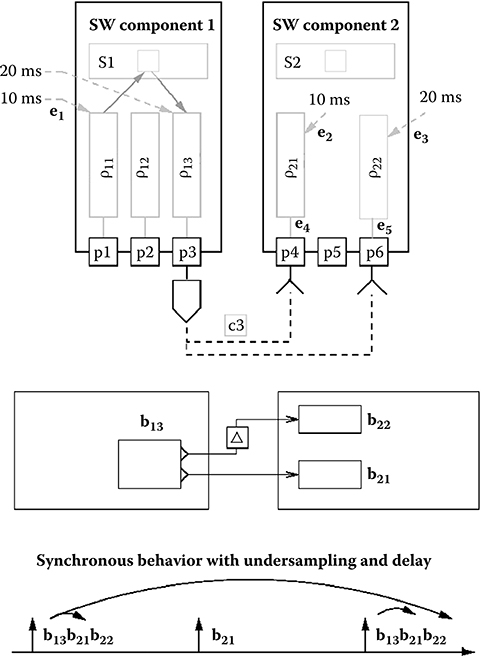
FIGURE 21.10 Semantics issues when mapping a typical synchronous behavior in AUTOSAR.
The activation events of the blocks are synchronized, whereas RTE periodic events are local to each ECU and, in principle, with an unspecified relative phase.
The causal dependency between the inputs and outputs of blocks b21 and b22 defines a partial order (a set of precedence constraints) in the execution of blocks. Expressing this partial order using the RTE timer events or the events on data ports is not trivial. In our example, ρ21 must be activated after the production of data from ρ13 but only once every two activations of ρ13.
Finally, communication with a unit delay is difficult to express without adding a dedicated runnable.
In reality, even if a translator from a Simulink to an AUTOSAR model would be highly appropriate for matching the needs of a model-based development flow, it is the inverse transformation that has received most of the attention and support from both sides (the AUTOSAR consortium and MathWorks®).
As part of the AUTOSAR specification, the document “Applying Simulink to AUTOSAR” [20] defines the rules to translate an AUTOSAR component (or a set of components) into a corresponding set of Simulink subsystems. Although one of the purposes of the document is to allow simulation of AUTOSAR components in a Simulink environment, a large part of the document is dedicated to the definition of translation methods that allow seamless integration of the code generated using the tools by MathWorks tools with the code generated by AUTOSAR tools for the RTE layer.
Also, the Real-Time Workshop® and Simulink Coder® [21] code generator products for the Simulink simulation environment today include a large section that is dedicated to the production of AUTOSAR components specifications and AUTOSAR-compatible code from sections of a Simulink model. However, a careful read of these user manuals reveals that in essence what is provided is not a general-purpose translator from Simulink to AUTOSAR, but a set of modeling guidelines and configurations of the code generators to produce an implementation of Simulink subsystems that is compliant with the AUTOSAR interfacing conventions and the RTE event semantics, including the automatic generation of AUTOSAR (XML) component specifications.
In essence, the model-to-model translation is straightforward (the code generation issues are more involved). AUTOSAR runnables are made to correspond to Simulink subsystems. When the AUTOSAR component has a single runnable, the subsystem models both the component and its runnable. When multiple runnables are part of the AUTOSAR component, each runnable corresponds to an atomic subsystem and the component to a wrapping (virtual) subsystem.
Sender/receiver ports map onto Simulink ports. A required port or R-Port is a Simulink input and a P-Port is a Simulink output port, with the corresponding definition of interfaces mapped onto Simulink BusObjects. Some more complexities are necessary to represent the client/server (method-oriented) interfaces of AUTOSAR. The AUTOSAR standard declares the client/server communication among application components out of scope and limits itself to modeling the client ports of application components that are requesting (standardized) services from the BSW or the ECU abstraction. Also, in the case of ports modeling BSW services, the correspondence consists of a block (Stateflow® or S-function) obtaining as input the set of required arguments and calling internally the desired function with its standardized signature. Of course, capturing the semantics for the time at which the service is invoked is entirely another story, given that this semantics is not explicit in the AUTOSAR model.
With runnables, however, the situation is clear: runnables are executed in response to RTE events, which can be periodic (time driven) or generated by operations on ports. Correspondingly, in Ref. [20], a canonical pattern is defined where runnables are function-call subsystems in Simulink and for each SWC the corresponding Simulink subsystem defines an additional port, dedicated to the set of RTE events that trigger its runnables. The RTE events are collectively joined in a bus that is input to this special port. A bus selector is then used to route the appropriate events as triggers to the runnable subsystem. An example is shown in Figure 21.11 showing two cooperating components with their RTE event ports and the internals of the Component 1 subsystem in Figure 21.12 showing the bus selector with the two outgoing function call signals for the runnables.
Inter-runnable communication is handled by inter-runnable ports, which correspond to additional input and output ports on the runnables subsystems. The implicit or explicit communication model affects the code generation mode but not the simulation model, where access to the ports always occurs implicitly according to the Simulink semantics.
When it comes to the composition of the AUTOSAR components and the system-level simulation, the recommended canonical pattern is the one represented in Figure 21.13. In this pattern, the RTE events are generated by a single subsystem labeled as Function Call Creation. The rationale for such a centralized generation is to collect in a single block the logic controlling the execution order of runnables. The internals of this subsystem are not specified in Ref. [20] as it states that “it is up to the user to implement this in an appropriate way.”
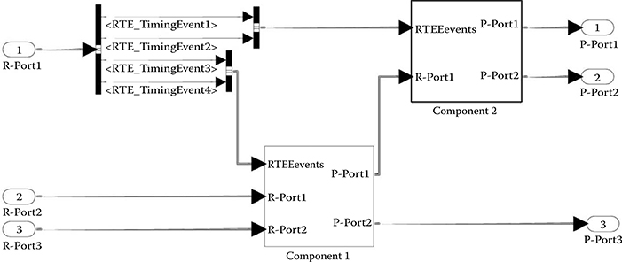
FIGURE 21.11 Simulink® model for forwarding runtime executable events to components and realizing data communication.
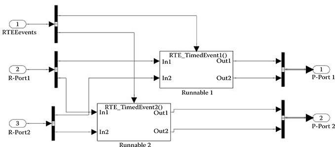
FIGURE 21.12 Simulink® model for an AUTOSAR component with two runnables.
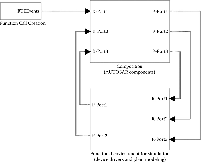
FIGURE 21.13 Canonical pattern for the Simulink® representation of an AUTOSAR composite.
21.5 Simulation, Timing Analysis, and Code Generation: Consistency Issues and Model Alignment
An AUTOSAR model has (at least) three different objectives: it can be used to simulate the functional behavior, it can be used to perform worst-case timing analysis using suitable tools and, of course, it is used to generate the code for the implementation of the model on a target platform. The same model should be used for the three purposes or at least very limited changes should be required to obtain the three different objectives of validation by timing analysis, simulation, and finally automatic implementation by code generation.
To illustrate some of the issues, let us consider a fuel injection system. In this control application, several functions must be executed in response to events that correspond to a given rotation angle of the engine shaft. In practice, a crankshaft position sensor provides a reference hardware signal that is sporadic in nature and depends on the rotation speed of the shaft. This signal triggers a set of functions, typically mapped for execution onto a single task.
In AUTOSAR, a sporadic signal of this type cannot be directly defined as an RTE event. However, inside the application model, the runnables that are executed in response to the crankshaft position signal must be activated in response to an RTE event, given that this is the only legal way for a runnable to be activated in AUTOSAR.
One possible solution is the following. A BSW runnable represents the interface between the hardware signal coming from the crankshaft position sensor and the application tasks. This BSW runnable writes into a sender/receiver port to forward to the application the sensor position signal. The SWCs containing application runnables that must be activated in response to this signal will define a matching port. Inside them, the runnables are then defined to be activated on the event of data received on the port.
The BSW component is the main variation point with respect to the three model versions. For simulation purposes, the BSW runnable is activated periodically by a counter/alarm pair. Inside, it contains the simulation stub that generates the stream of the crankshaft sensor signals. These signals are represented by writes into the sender/receiver port on which all the application-level runnables that must perform actions in correspondence to these events are waiting.
For code generation purposes, the BSW component is replaced by a device driver that will explicitly call the RTE API function for writing into the data port at the end of its execution.
Finally, for the purpose of worst-case timing analysis, it is necessary to have information about the worst-case arrival rate of the activation events for the sporadic task onto which all the runnables reacting to the crankshaft position sensor events are mapped. In AUTOSAR 4.0, this indication could come directly from a timed event triggering information (Figure 21.8). In past releases of the standard, a timing analysis tool would have to deduce the rate from the rate of the writes into the corresponding data port, which would require navigating the communication model graph to the BSW runnable and the corresponding alarm (which, however, can only be periodic since no AUTOSAR versions up to 3.2 allow sporadic activation events).
21.6 Conclusions
This chapter provides an introduction to AUTOSAR as a language for system-level modeling and SWC modeling. Focus is on the issues related to the use of AUTOSAR models for simulation purposes and on the integration of AUTOSAR models with heterogeneous models (such as Simulink) for behavioral modeling. Also, the new timing model of AUTOSAR is analyzed with respect to its capability of defining a discrete-time base for simulation purposes or, in general, a timing model that allows seamless migration or integration of SR models. In conclusion, AUTOSAR is a promising solution for filling some of the gaps of modern methodologies with respect to platform modeling and system-level modeling and analysis, but still lacks the support of a formal (based on mathematical rules) MoC and of timed events.
Acknowledgments
The author wishes to thank Giacomo Gentile and Nicola Ariotti of Magneti Marelli SpA for their insightful discussions on the modeling of the fuel injection case study.
References
1. MathWorks. The MathWorks Simulink and Stateflow User’s Manuals, available at http://www.mathworks.it/help/toolbox/simulink/ (04/04/12).
2. The AUTOSAR Consortium. The AUTOSAR Specification v 4.0, available at www.autosar.org (04/04/12).
3. Scharpf, Johannes, Robert Hoepler, and Jeffrey Hillyard. 2012. “Real-Time Simulation in the Automotive Industry.” In Real-Time Simulation Technologies: Principles, Methodologies, and Applications, edited by Katalin Popovici, and Pieter J. Mosterman. Boca Raton, FL: CRC Press.
4. Wei, Zheng, Qi Zhu, Marco Di Natale, and Alberto Sangiovanni-Vincentelli. 2007. “Definition of Task Allocation and Priority Assignment in Hard Real-Time Distributed System.” In Real-Time Systems Symposium, December 3–6, Tucson, AZ, pp. 161–70.
5. Davare, Abhijit, Qi Zhu, Marco Di Natale, Claudio Pinello, Sri Kanajan, and Alberto Sangiovanni-Vincentelli. 2007. “Period Optimization for Hard Real-Time Distributed Automotive Systems.” In Proceedings of the Design Automation Conference, June 4–8, San Diego, CA, pp. 278–83.
6. The AUTOSAR Consortium. The AUTOSAR Timing Extensions, available at http://www.autosar.org/download/R4.0/AUTOSAR_TPS_TimingExtensions.pdf (04/04/12).
7. The AUTOSAR Consortium Artop Group. The AUTOSAR Tool Platform User Group, available at http://www.artop.org/ (04/04/12).
8. The Eclipse Foundation. The Eclipse Foundation open source community website, www.eclipse.org (04/04/12).
9. dSPACE. The dSPACE SystemDesk, product documentation available at http://www.dspace.com/en/inc/home/products/sw/system_architecture_software/systemdesk.cfm (04/04/12).
10. Vector. Vector AUTOSAR Solutions, product information available at http://www.vector.com/vi_autosar_solutions_en.html (04/04/12).
11. Geensoft. The AUTOSAR Builder, product information available at http://www.geensoft.com/ja/article/autosarbuilder/ (04/04/12).
12. Elektrobit. EB tresos, product information available at http://www.automotive.elektrobit.com/home/ecu-software/eb-tresos-product-line.html (04/04/12).
13. Templ, Josef, Andreas Naderlinger, Patricia Derler, Peter Hintenaus, Wolfgang Pree, and Stefan Resmerita. 2012. “Modeling and Simulation of Timing Behavior with the Timing Definition Language (TDL).” In Real-Time Simulation Technologies: Principles, Methodologies, and Applications, edited by Katalin Popovici, and Pieter J. Mosterman. Boca Raton, FL: CRC Press.
14. Reindl, Florian. Performance evaluation of AUTOSAR based systems, available at http://www.eb-tresos-blog.com/2010/12/performance-evaluation-of-autosar-based- systems/ (04/04/12).
15. Bernard, Zeigler, Tag Gon Kim, and Herbert Praehofer. 2000. Theory of Modeling and Simulation, 2nd ed. New York: Academic Press.
16. Gabriel, Wainer, and Pieter J. Mosterman. 2010. Discrete-Event Modeling and Simulation: Theory and Applications. Computational Analysis, Synthesis, and Design of Dynamic Systems. CRC Press, Boca Raton, FL, ISBN 9781420072334, December, 2010.
17. Krause, Matthias, Oliver Bringmann, Andre Hergenhan, Gokhan Tabanoglu, and Wolfgang Rosentiel. 2007. “Timing Simulation of Interconnected AUTOSAR Software-Components.” In Proceedings of the DATE Conference, April 16–20, Nice, France, pp. 1–6.
18. Grotker, Thorsten, Stan Liao, Grant Martin, and Stuort Swan. 2002. System Design with SystemC. Springer. Kluwer Academic Publisher, New york (now Springer), available on line at http://www.springerlink.com/content/p16217/?p=d25f5bad8b794111b6797650cabf04c9&pi=0 (04/04/12).
19. OSCI. The Open SystemC Initiative, web site http://www.accellera.org/home/ (04/04/12).
20. The AUTOSAR Consortium. The AUTOSAR Simulink Style Guide, available at http://www.autosar.org/download/AUTOSAR_SimulinkStyleguide.pdf (04/04/12).
21. Simulink Coder, product web page http://www.mathworks.it/products/simulink-coder/index.html (04/04/12).