
13 Interactive Flight Control System Development and Validation with Real-Time Simulation
Hugh H. T. Liu
CONTENTS
13.1 Flight Control System Development Process
13.2 Validation and Verification
13.3 Modeling and Simulation Platforms
13.4 Interactive Flight Control System Development Test Bed
This chapter describes the process of flight control system (FCS) development where simulation plays a critical role in interactive design, validation, and verification. Some simulation-based platforms are introduced. As a case study, one such interactive FCS development and real-time simulation test bed is presented.
13.1 Flight Control System Development Process
Because of the complexity of the system, modern aircraft development often adopts a systematic engineering process. The systems engineering has evolved to become a specialized engineering discipline. There are several proposed standards such as IEEE standard (IEEE-Std-1220-1998) and SAE standard (SAE-ARP-4754). Different standards may adopt slightly different practice. However, the core features of a valuable systems engineering process (SEP) should remain unchanged. The purpose of the SEP is to provide a systematic approach for product development and management from initial concept to final delivery. It is a generic problem-solving process that provides the mechanisms for identifying and evolving the product and process definitions of a system. The SEP applies throughout the system life cycle to all activities associated with product development, verification/test, manufacturing, training, operation, support, distribution, disposal, and human systems engineering. A typical SEP is described by a “V”-shape diagram, where the top-down line (the left-hand stroke) represents the process from top-level requirement analysis all the way down to detailed design, and the bottom-up line (the right-hand stroke) represents the process of verification and validation starting from the component level at the bottom all the way up to the top system level performance evaluation.
The FCS development process is no exception. The aim is at finding subsystems (control channels) to represent a solution, given the inputs and desired outputs or tolerable errors, and to integrate them into a functional system that performs its assigned tasks associated with flight mission. The design process can be broken into several phases that are extensively interrelated and interconnected [1,2]. After the overall system requirements are established, the basic functional block diagrams are determined, when characteristics of component parts that become unalterable are fixed. Once a best system has been selected through competing system assessment and trade-off study, the detailed design must be carried out and be validated, often through a series of system simulations and eventually ground and flight testing.
On the basis of operational needs, the FCS offers different functions at different levels. On the one hand, an automatic control (autopilot) provides “pilot relief” in continuous slow mode control such as pitch attitude hold, altitude hold, bank angle hold, turn coordination, and heading hold. The flight control can also be used as a landing aid in terms of glide slope control, localization to align the aircraft in the lateral direction, and the flare control. On the other hand, the FCS includes both stability and control augmentation, to provide stability or ensure appropriate handling qualities, and to provide a desired response to a certain control input. Examples of stability augmentation include the pitch damper, roll damper, and yaw damper. Examples of control augmentation may involve the pitch or roll rate control, or normal acceleration [3].
As a result, both the system design process and the flight control development require interactions between design and validation, often through extensive simulations. The effectiveness and efficiency of the development therefore depends on the smoothness in the iterations and cycles.
13.2 Validation and Verification
Requirement validation and verification (RV&V) is an integrated part of the SEP. On the one hand, validation is the process of ensuring the requirements are correct and complete and also ensuring compliance with system and airplane-level requirements. On the other hand, verification is the process of ensuring that an item complies with all of its design requirements. Requirement validation is embedded in the program risk management. It generally consists of two types of activities: (1) evaluation to ensure correctness and (2) assessment to ensure completeness and necessity. The major validation methods include test, analysis, demonstration, and inspection. The requirement verification determines whether the requirements have been fully complied with the design. The major verification methods include test, analysis, examination, and demonstration.
RV&V methods very much depend on the development environment that the systems engineer chooses. For control systems development, we are particularly interested in the simulation environment that supports validation and verification activities. The concept of “systems simulation” abandons a single, monolithic system development strategy and instead prescribes multiple, incrementally delivered development. It requires that individual control channels and specific functions are tested at an overall system level such that its correctness, completeness (validation), and compliance (verification) are evaluated. It is the highest level of integration and testing before the ground and flight-testing phase is initiated. Several systems simulation models are valuable in the FCS development.
Before a design becomes available or finalized, a rapid prototyping model allows the simulation model that represents the component under development be placed into the system platform for testing and demonstration. The design parameters are able to be tuned under this framework, and it is convenient to finalize the component product prototype. In a different scenario, some components are difficult to model in software, or the level of details and complexity can only be represented by the actual physical product. A hardware-in-the-loop (HITL) model provides a solution that the hardware be inserted into the simulation environment, to replace the simplified component software. It is expected that the HITL simulation not only provides physical component (the actual prototype) representation but also provides an opportunity to verify the accuracy of the model describing the component product. At a later stage, the pilot-in-the-loop (PITL) flight simulation would enable the pilot(s) to operate the virtual aircraft and evaluate its handling qualities.
The challenges when dealing with a heterogeneous simulation environment involve several fronts. From the modeling perspective, the level of fidelity shall be identified. From the integration point of view, special attention shall be placed on the interface design to ensure consistency and compatibility. On the RV&V side, the quantification of requirements, the specification executability, and the traceability shall be represented properly. On the simulation itself, real-time simulation and automation (e.g., automated code generation) aspects shall be considered. In addition, the simulation platform being developed shall also be extensible, scalable, and interoperable. If possible, the commercial-off-the-shelf (COTS) products or modules shall be looked into to take advantage of their maturity, standard, and cost benefits.
13.3 Modeling and Simulation Platforms
The engineering systems development process typically has a waterfall view as if the different development stages were performed chronologically and independent of each other, when in practice they are extensively interrelated and interconnected. Moreover, a system often consists of multiple subsystems and components that are also interacting or even have conflicting characteristic features. Therefore, the entire development relies on iterative cycles between design modifications and integration and testing verifications, until the final design “converges.” Unfortunately, this also makes the design process time-consuming and fragile: a slight change may require a completely new cycle of redesign. The necessity for an integrated development process arises from complexity of engineering intensive applications such as in aerospace.
Several research programs that aim at developing an integrated development framework have been proposed and developed over the years. Since 1994, NASA has been funded and tasked at a national priority level to develop and deploy advanced technologies in the general aviation industry. The Advanced General Aviation Transport Experiment (AGATE) seeks to improve utility, safety, performance, and environmental compatibility [4]. A joint development of a state-of-the-art computational facility for aircraft flight control design and evaluation is referred to as CONDUIT (Control Designer’s Unified Interface) [5]; it provides an environment for design integration and data resource management. A Defense Advanced Research Projects Agency (DARPA) research program entitled Software-Enabled Control (SEC) [6] was initiated to integrate multimodal and coordinated operation of subsystems and enable large-scale distribution of control. Under this program, an open control platform (OCP) was developed to integrate control technologies and resources. The approach is to use a hierarchical control structure where mission planning situation awareness is at the highest level, the flight control is at the lowest level, and a midlevel controller coordinates the transitions between model selection and model implementation through mode switching and reconfigurable control. The emerging field of multiparadigm modeling addresses the directions of research in model abstraction, transformation, multiformalism modeling, and metamodeling [7]. They are concerned with the models of system behavior, the relationship between models at different levels of details, conversion of models expressed in different formalism, and the description of classes of models, respectively.
13.4 Interactive Flight Control System Development Test Bed
One of the key requirements for an integrated development process is the “ plug- and-play” capability, which enables decoupled component (subsystem) design and integrated testing based on the same model. Therefore, design decisions are gradually finalized through iterations between component-level and system-level developments. For complex control systems development, strategies have been proposed or developed including the computer-automated multiparadigm modeling, actor-oriented control system design approach, cosimulation, code integration, model encapsulation, and model translation ([8] and the references therein). Generally speaking, not only are these efforts time-consuming, but they are also still facing technical difficulties to reach seamless integration. Furthermore, the auto-generated code is often not sufficiently optimized to be used in a production environment. As the complexity of the system is increasing rapidly, these challenges become more and more evident. In this section, we introduce an interactive design and simulation platform for flight vehicle systems development. The proposed platform adopts the cosimulation concept and avoids code generation challenges faced by other integration approaches. It enables the component design “plug-and-play” in a systems simulation environment, thereby bringing the “systems simulation” into the “control design” for integrated development. Moreover, the seamless interactive design and simulation is achieved by an adaptive “connect-and-play” capability. The following presentation is based on the work by Liu and Berndt [8].
A popular approach in FCS development follows the concept of code encapsulation in principle. The controller is designed and validated in isolation by desktop off-line simulation. The controller algorithm codes are generated (in C code as one example). Then, encapsulated as a monolithic submodel, it is integrated into the model of an enclosing system for systems validation and verification. The challenges of the code-generation-based integration approaches include the level of automation, compatibility, and synchronization of the models and simulations. Since design codes are used as the media, one must ensure that the generated codes can work on heterogeneous simulation platforms, with proper interfaces. If so, it is expected that the code generation can be processed automatically, to avoid tedious manual labor and errors. These challenges are still open research topics. In this section, instead, we adopt a different integration strategy that is similar to cosimulation in principle. As shown in Figure 13.1a, this proposed interactive platform allows the component model to be simulated (plug-and-play) in a different, system-level environment. Moreover, the platform is adaptable such that the systems simulator can “connect” to the design model directly. We believe that this “connect-and-play” capability is one significant improvement over the “plug-and-play” capability. Since there is only one physical design model that takes residence at the component level, one can work with this model to make modifications and perform testing “online” without the intermediate code-generation process. Obviously, the “connect-and-play” property and the adaptability make the design and simulation platform truly interactive and integrated in development. Under the proposed platform (Figure 13.1b), the integrated FCS results in a multiparadigm control framework. It represents a standard FCS block diagram with some special features.
The blocks with a drop-down shadow represent “swapping” features. The guidance and command block represents the flight path generation (guidance) or command inputs (for controller design). The actuation and sensor blocks can be replaced by software modules with different levels of fidelity or even hardware equipment. The vehicle dynamics module can also be replaced by different software modules for different simulation purposes. A simplified linearized dynamics model is used for control system design, while full-scale nonlinear flight equations will be used for high-fidelity simulations such as flight simulations. To emulate the reality that different flight systems components are physically installed in different locations and their interactions are communicated through mechanical links or electrical bus, the proposed framework allows for a distributed modeling structure. Each block can be individually modeled, as one software module in different processors. Therefore, it is possible to distribute different parts of a computing task across individual processors operating at the same time, or “in parallel,” and thus reduce the overall time to complete the task. Furthermore, the distributed modeling structure makes it feasible to “swap” different modules of the same block, including the HITL simulation. Because of the distributed modeling and “swapping” feature, it is possible to replace block modules developed under different platforms, and even to run simulations on machines from different manufacturers. Therefore, the proposed framework supports heterogeneous simulations.
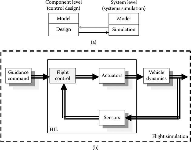
FIGURE 13.1 (a) An illustration of cosimulation concept; (b) Interactive flight control system design and simulation platform.
To demonstrate the proposed FCS framework and the interactive design and simulation platform, an experimental test bed is set up. A real-time systems simulator and a flight training device (RTSS-FTD) are equipped to provide a suitable proof-of-concept facility, as shown in Figure 13.2.
The RTSS facility is a networked cluster of high-end COTS computers. Its core computing features include three host computers, each having dual-Pentium processors running Windows 2000 OS; four real-time computers, each having dual-Pentium processors running the QNX real-time operating system; and real-time nodes that are directly connected by 400 Mbit/s FireWire and communicate with hosts over a dedicated 100-Mbit/s Ethernet network. Furthermore, the system consists of a 108 multiple channel input/output (I/O) system for HITL simulation. The RTSS is also connected through a 1.25 Gb/s Giganet to a similar facility to share data and sources, and it is connected to a 56-alpha-processor high-power computer for off-line computing and simulation, as well as data storage. This configuration provides the following key capabilities to support our proposed framework.
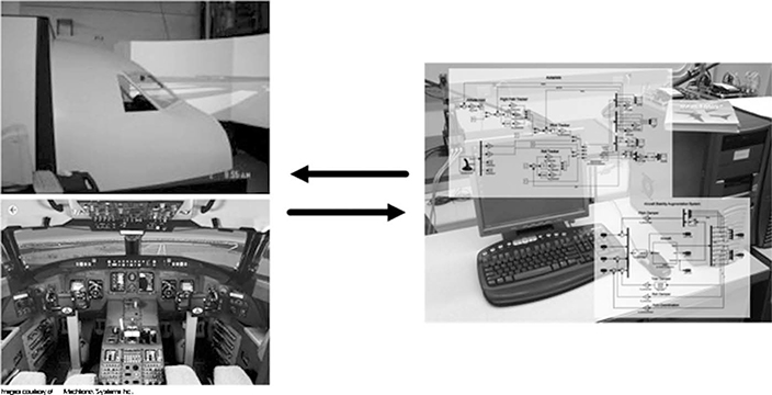
FIGURE 13.2 Integrated flight control system development test bed.
A separate FTD is set up for flight simulation. It simulates the operation of a generic jet aircraft within the tolerances and conditions set out by the Transport Canada Authority. The major aircraft subsystems include the automatic controls; the auxiliary power unit (APU); doors; the engine indication and crew alerting system (EICAS); the electrical systems; the environmental control systems; flight controls and flight instruments; the fuel, pneumatic, and hydraulic systems; the landing gear; the lighting; and the navigation and communications systems. The design of the FTD is such that all the simulated functionality is concentrated in the software model running on the host computer. This software model contains all the mathematical and logic modeling to make the FTD behave like the Generic Jet aircraft. All the other computers and hardware are I/O interfaces between the pilot/copilot and the model software running on the host computer. The control loading is handled by a PC on the network. It communicates with the host on the Ethernet switch. This computer has digital wiring running to the primary flight controls in the cockpit. The computer systems are networked through a 100 Mbaud Ethernet switch. All the simulated aircraft panels are intelligent; they each contain an embedded CPU that manages their local I/O and communicates with the host computer through a CAN bus network. The aircraft flight and subsystem models are developed using the C programming language. The visual database is developed using the MultiGen paradigm (www.presagis.com). The control system is developed under the MATLAB® (version 7.6) and Simulink® (version 7.1) platform. Both MATLAB and Simulink are software packages provided by MathWorks Inc. (www.mathworks.com). A fully functional FTD also includes an instructor operation station (IOS).
In summary, the RTSS is able to simulate the aircraft systems and flight maneuvers. The features of reconfigurability, modeling, and customization of cockpit displays are critical to our systems integration research. The FTD presents a more complete and realistic aircraft model, which includes factors not taken into account in the RTSS development. It offers a different perspective as the flight mission may be observed from a cockpit with out-the-window visual and instrument displays. The RTSS and FTD facilities are connected through Ethernet cables to form a networked RTSS-FTD test bed for integrated modeling and simulation activities.
To use the FTD as a test bed for interactive controller design and simulation, a network connection is established for “connect-and-play.” As introduced before, the control development environment uses the MATLAB and Simulink platform that offers an application programming interface called “S-function” that can be used to integrate blocks with user-defined behavior into a Simulink block diagram. The idea is to let an S-function for MATLAB and Simulink work as a network I/O layer, which outputs the current state vector of the FTD and takes control commands as inputs, as it is commonly done with HITL approaches (Figure 13.3). Note that the control input can carry additional payload, if necessary. In particular, the S-function allows for three values of wind components, which, if given, will be used to overwrite the built-in wind model.
It was then decided that a transmission control protocol and Internet protocol (TCP/IP) connection offers the robustness needed for controller operation. The packet format used for the network connection is simple, yet extensible. A fixed-length integer specifying the total packet length is followed by an arbitrary number of triples specifying an identifier, a value, and a delimiter. The S-function is written in the programming language C and can be further customized at compile time using preprocessor macros. This way, among other preferences, maximum allowable packet length and floating point data formats can be adjusted.
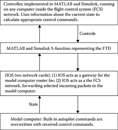
FIGURE 13.3 Network communication.
13.5 Design Case Study
We provide a business jet aircraft model to illustrate the interactive FCS development. The 50-seat Canadair Regional Jet 200 (CRJ200) series was announced by Bombardier in 1995 and introduced into service in 1996. The design of the CRJ200, which evolved from the Challenger 604 business jet, is for regional airline operations. The aircraft is equipped with high-efficiency engines giving a range up to 3050 km. The wings are transonic and are fitted with winglets for efficient high-speed flight.
The general equations of motion of this flight vehicle are described by the general rigid-body dynamics when choosing the body reference frame:
where the aerodynamic forces and moments are expressed in the body frames [X Y Z]T and [L M N]T, respectively. In most cases, a perturbed fluid-aerodynamic force (moment) is a function of perturbed linear and angular velocities and their rates are as follows:
Thus, the aerodynamic force at time t0 is determined by its series expansion of the right-hand side of this equation:
and so on are known as the stability derivatives, or more generally as aerodynamic derivatives. Because of the assumed symmetry of the vehicle, derivatives of X,Z,M with respect to motions out of the longitudinal plane are zero. This may be visualized by noting that X,Z,M must be symmetrical with respect to lateral perturbations. In other words, we neglect the symmetric derivatives with respect to the asymmetric motion variables, that is, for aerodynamic force X, Xv = Xp = Xr = 0, and so on:
The fully nonlinear dynamic model of the aircraft is implemented in MATLAB and Simulink, as shown in Figure 13.4, where the states also include the inertial position displacement xE, yE, altitude h, and control inputs are specified by the control surface deflection angles:
In this example, we design and test the altitude hold and steady-turn (heading hold) autopilot function (Figure 13.5). To carry out the control design, we start by developing a linearized lateral system design model about a reference equilibrium. The reference steady flight condition is cruising at 33,000 ft altitude, Mach 0.74 (or speed of 726.5928 fps). The linearized G(s) is represented by
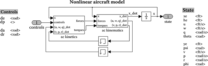
FIGURE 13.4 Nonlinear aircraft model.
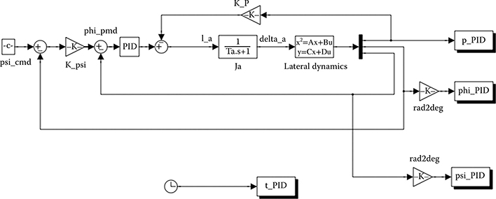
FIGURE 13.5 Autopilot in heading control.
where ψ is the heading angle to be regulated.
We then use the linear system platform LinAC _ Hdg _ Hold _ Sample.mdl to design a heading-hold controller. During the steady flight at 33,000 ft, command the airplane for a steady 90-degree turn under the heading-holding autopilot, that is, the autopilot controls the heading step change of ψ = 0 ⇒ 90 (deg).
The design requirements are as follows:
The aircraft is stable during the motion.
The heading overshoot is less than 10%.
The steady heading error is less than 5%.
A sample proportional-integral-derivative (PID) control structure is provided. Once the design is complete and satisfactory, the validation is carried out through simulations on the nonlinear Simulink model nonLinAC _ Hdg _ Hold _ Sample.mdl (Figures 13.6 and 13.7). Two test cases should be performed:
Heading command of ψ = 90 (deg) only while maintaining altitude at 33,000 ft.
Heading command of ψ = 90 (deg) with altitude climb to 35,000 ft.
The linear simulation result is shown in Figure 13.8; the nonlinear simulation results are presented in Figures 13.9 and 13.10.
The next step is to incorporate the design into the interactive FCS platform as described before. To assure that there exists a stable solution and it is feasible to run successful flight simulation, we demonstrate a successful design, using a linear quadratic regulation (LQR) approach. In this case, both nonlinear off-line simulation results (Figure 13.11) and flight simulation results (Figure 13.12) are quite satisfactory. Note that the flight simulation model is similar to Figure 13.7 except the aircraft model inside the box will directly connect to the FTD according to the communication protocol. The snapshots of the FTD simulation results can either be read from the cockpit panel or recorded at the remote desktop computer, as shown in Figure 13.13.
13.6 Challenges and Lessons Learned
To develop the interactive FCS and implement it to the flight simulation platform, a number of challenges were encountered and have been addressed in the research investigation.
The design, simulation, and integration architecture. The I/O interface is required to be consistent, such that the model can be substituted seamlessly.
The switch between the simulator built-in autopilot function and the designed one must be smooth. It is activated by a command to turn on the design (and automatically overwrites the default one). It is automatically turned off once the testing phase is complete.
Version control. Even though it is a relatively trivial issue, we did experience on a couple of occasions that the off-line design and simulation model was not compatible with the nonlinear platform for flight simulation. It was solved by specifying the version and release of the software environment.
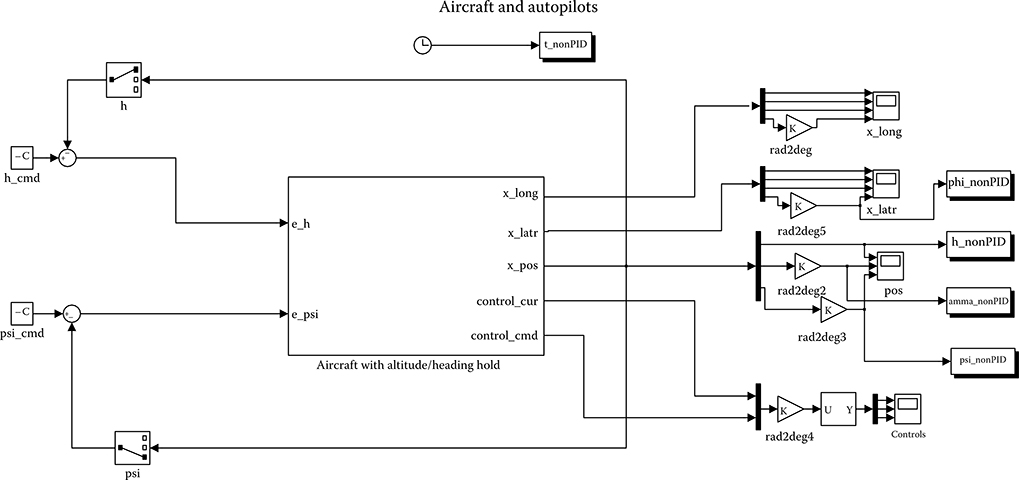
FIGURE 13.6 Nonlinear model for simulation.
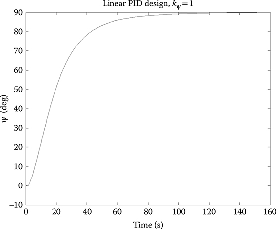
FIGURE 13.7 Control design implemented in nonlinear model.
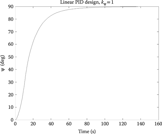
FIGURE 13.8 Linear simulation result: ψ.
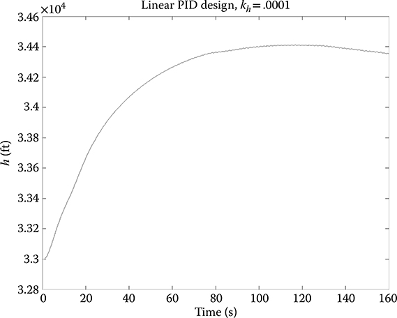
FIGURE 13.9 Nonlinear simulation result: ψ.
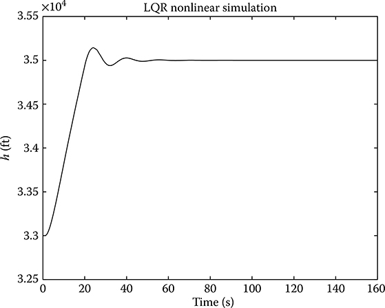
FIGURE 13.10 Nonlinear simulation result: h.
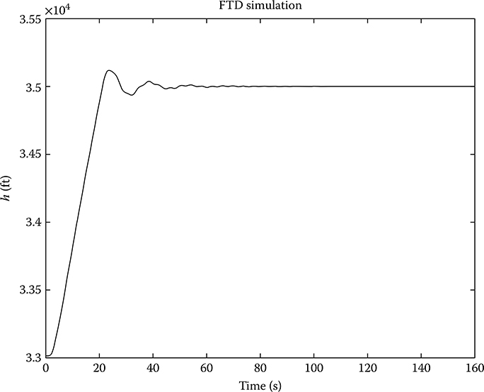
FIGURE 13.11 Nonlinear simulation of altitude from linear quadratic regulation design.
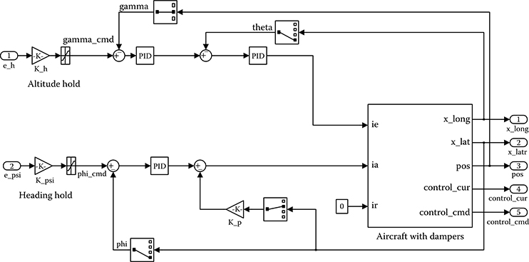
FIGURE 13.12 Flight simulation of altitude from linear quadratic regulation design.
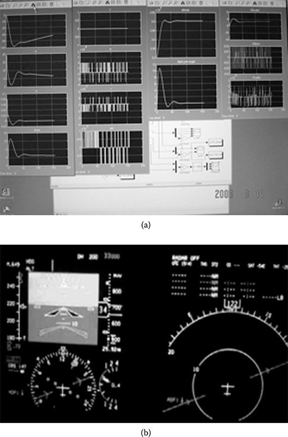
FIGURE 13.13 Interactive flight control system flight training device simulation (a) real-time simulation results display; (b) real-time cockpit display.
13.7 Conclusions
This chapter presents an FCS development using an innovative, interactive simulation platform. It integrates design, testing, and flight simulation to provide a close-to-reality engineering development practice. Valuable lessons are learned through “flight testing” experience. It also provides feedback for design fine-tuning and improvement.
References
1. McRuer, Duane, Irving Ashkenas, and Dunstan Graham. 1973. Aircraft Dynamics and Automatic Control. Princeton, NJ: Princeton University Press.
2. Nelson, Robert C. 1998. Flight Stability and Automatic Control. 2nd ed. Boston, MA: WCB McGraw-Hill.
3. Pratt, Roger W. 2000. Flight Control Systems. Reston, VA: AIAA.
4. Thompson, J. Garth. 1996. “Aircraft/Control System Simulation.” In IEEE International Conference on Control Applications, Dearborn, MI, September 15–18, 1996, pp. 119–24.
5. Tischler, Mark B. et al. 1999. “A Multidisciplinary Flight Control Development Environment and Its Application to a Helicopter.” IEEE Control Systems 19: 22–33.
6. Schrage, Daniel P., and George Vachtsevanos. 1999. “Software-Enabled Control for Intelligent UAVs.” In International Symposium on Computer Aided Control System Design, Hawaii.
7. Mosterman, Pieter J., Janos Sztipanotits, and Sebastian Engell. 2004. “Computer Automated Multiparadigm Moldeing in Control Systems Technology.” IEEE Transactions on Control Systems Technology 12 (2): 223–34.
8. Liu, Hugh H.T., and Holger Berndt. 2006. “Interactive Design and Simulation Platform for Flight Vehicle Systems Development.” AIAA Journal of Aerospace Computing, Information, and Communication 3 (1): 550–61.