CHAPTER 3
Basic Networking and Communications
In this chapter, you will learn about
• Use cases
• The OSI and TCP/IP models
• Bus, star, tree, token ring, and mesh network configurations
• Common protocols in the TCP/IP suite
• Ports and protocol numbers used with common protocols
• Different network and trust architectures such as the Internet, DMZs, and transitive trusts
• Wireless security protocols such as WPA, WPA2/802.11i, AES, and TKIP
• Wireless technologies such as Bluetooth, NFC, RFID, 802.11, WiMAX, GSM, and 3G
Understanding Use Cases
The 2018 version of the (ISC)2 Systems Security Certified Practitioner (SSCP) exam outline added the phrase “Common use cases” for secure protocols. This phrase might be unfamiliar, but don’t let it throw you. You can simply think of this as a goal that an organization wants to achieve.
As an example, an organization may decide that it wants to allow employees to access the internal network from remote locations in a secure manner. A use case to support this goal might be “create a secure virtual private network (VPN).”
Use cases are implemented differently by different professionals. For example, developers often create use cases to help them define the requirements for an application. Marketing and sales people sometimes create use cases to help them define sales goals. Again though, the SSCP exam limits use cases to secure protocols. While reading through this chapter, you’ll see explanations of how various protocols are used. These implementations can also be described as use cases.
Reviewing the OSI Model
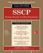
The International Organization for Standardization (ISO) developed the Open Systems Interconnection (OSI) Model as a standard model for network communications. It describes a framework for connecting multiple computers to each other and allows dissimilar networks to communicate with each other. It includes seven layers, and each layer focuses on a set of specific tasks or functions.
Data is packaged, or encapsulated, at each layer with additional data that the layer requires. Generically, the encapsulated data is a datagram. However, datagrams have specific names at each layer. For example, at the lowest layer (the Physical layer), data arrives as bits (ones and zeros). The next layer (the Data Link layer) adds more data, and packages the data into frames. Figure 3-1 shows a diagram of the OSI Model identifying the layers and the data encapsulation names. The following subsections describe these different layers.
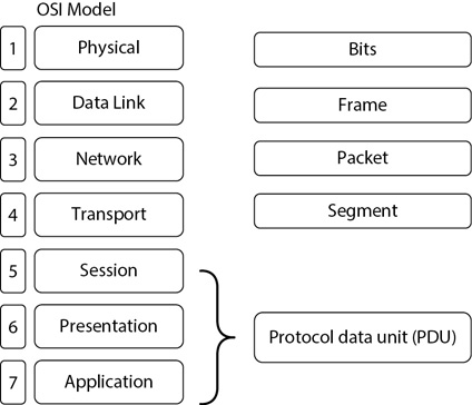
Figure 3-1 OSI Model

TIP Many people memorize the layers of the OSI Model with a mnemonic. For example, All People Seem To Need Data Processing (for Application, Presentation, Session, Transport, Network, Data Link, and Physical) is one. Please Do Not Throw Sausage Pizza Away (for Physical, Data Link, Network, Transport, Session, Presentation, and Application) is another.
For the SSCP exam, you don’t need to know the OSI Model as in-depth as you would for a networking certification such as Cisco’s CCNA or CompTIA’s Network+. However, you should have a basic understanding of the model, including what occurs at each layer. This section introduces each of the OSI Model layers. The “Reviewing Basic Protocols and Ports” section later in this chapter includes a figure that maps protocols to specific layers.
The Physical Layer (Layer 1)
The Physical layer provides a direct connection to the network. It defines how data is passed onto the network, including the transmission method, such as via wired or wireless techniques. The Physical layer includes physical items such as cabling, hubs, repeaters, and wireless radio transmissions required to provide a connection to the network.
Security at this layer focuses on protecting access to the network connections. If attackers are able to connect a protocol analyzer or sniffer via unprotected cabling, they can intercept data going across the network.
TIP A sniffer can capture and analyze packets sent over both wired and wireless networks. For example, if systems send credentials such as a username and password over a network in clear, readable text, the attacker can learn the credentials by capturing and analyzing the traffic. In contrast, attackers are unable to read the data if systems encrypt it prior to transmission, making the text unreadable.
The following list describes the different transmission media types commonly used to transmit data:
• Coaxial cable Coaxial cable is similar to the cable used for cable television. It’s an older technology that is rarely used on networks today, though it was commonly used in early bus networks (described later in this chapter). It is relatively easy for an attacker to tap into a coaxial cable connection.
• Twisted pair This is the most commonly used media for data transmissions. Unshielded twisted pair (UTP) does not have shielding and is susceptible to electromagnetic interference (EMI) and radio frequency interference (RFI). Shielded twisted pair (STP) provides protection against EMI and RFI. The EIA/TIA-568 standards define several categories of twisted pair cables. Common standards are Cat 5e and Cat 6. It is relatively easy for an attacker to tap into a twisted pair connection.
• Fiber-optic cabling Fiber provides the highest bandwidth and can support cable runs up to 40 kilometers. Although more expensive than copper cable such as twisted pair, fiber is becoming more and more popular. It is free from EMI and RFI issues and it is harder to tap into than wireless, twisted pair, and coaxial.
• Wireless transmissions Wireless transmissions use radio frequency transmissions to broadcast signals over the air. Because they travel over the air, they are the easiest to intercept.

EXAM TIP Cable standards are defined on the Physical layer. Wireless transmissions are the easiest to intercept, and fiber connections are the most difficult to tap into.
Data traveling on the Physical layer is packaged and transmitted as bits (ones and zeros) and bit streams. The Physical layer converts the ones and zeros from the media and passes a bit stream to the Data Link layer, which packages the data as a frame.
The Data Link Layer (Layer 2)
The Data Link layer provides reliable delivery of data across the network and establishes communication links between devices over a network. It includes two sublayers. The Media Access Control (MAC) sublayer interacts with the Physical layer and includes the MAC address (also called the physical address or hardware address). The Logical Link Control sublayer interacts with the Network layer.
Although manufacturers assign a MAC address to network interface cards (NICs), it’s worth noting that it’s possible to assign a different MAC address to a NIC by using software. This allows an attacker to spoof the source MAC address so that traffic appears as though it’s coming from a different computer.
Basic layer 2 switches work at this layer. As traffic comes into a switch on a physical port, the switch identifies the MAC address of the computer sending the data. It then creates a table mapping the MAC address to the physical port. When the switch receives unicast traffic for that computer, the switch sends the data to that port only.
Data traveling on the Data Link layer is packaged and transmitted as frames. The Data Link layer includes orderly delivery of frames and error notification if frames are not delivered properly.
EXAM TIP The Data Link layer is the only layer that includes sublayers. It includes the Media Access Control (MAC) sublayer, which defines MAC addresses (or physical addresses), and the Logical Link Control sublayer. Data is packaged in frames, and the Data Link layer ensures orderly delivery of frames.
The Network Layer (Layer 3)
The Network layer provides routing for data across a network by analyzing the Internet Protocol (IP) address and determining the best route to the destination computer. This layer also controls the flow of data across the network.
Routers and layer 3 switches are the primary hardware devices used at this layer. Routers use access control lists (ACLs) for basic packet filtering to control traffic. An ACL can block or allow traffic based on IP addresses, logical ports, and even some protocols such as Internet Protocol security (IPsec, identified with protocol numbers 50 and 51). Data traveling on the Network layer is packaged and transmitted as packets.
IP is the protocol used for addressing. Currently both IPv4 and IPv6 addresses are in use on the Internet and in many internal networks.
EXAM TIP Routers and layer 3 switches operate on the Network layer and determine the best route based on the destination IP address (also known as the logical address). Both IPv4 and IPv6 addresses are defined on this layer.
The Transport Layer (Layer 4)
The Transport layer provides reliable end-to-end communication services for applications, and includes error detection and recovery mechanisms. Data traveling on the Transport layer is packaged and transmitted as segments. Many of the logical port assignments for upper-layer protocols occur on this layer. Two primary protocols used at this layer are Transmission Control Protocol (TCP) and User Datagram Protocol (UDP).
TIP Well-known ports are logical numbers matched to specific protocols. For example, Hypertext Transfer Protocol (HTTP) uses the well-known port of 80. By blocking port 80, the router’s ACL blocks HTTP traffic that is using port 80. The port number is embedded in the datagram.
TCP
TCP is a connection-oriented protocol that provides guaranteed, reliable communication for devices on a network. It uses packet sequencing, and the destination acknowledges every packet that it receives. A three-way handshake establishes a TCP connection.
In Figure 3-2, a client is establishing a TCP session with a server. In the first step of the three-way handshake, the client sends a packet with the synchronize (SYN) flag set. The server responds with both the acknowledge (ACK) and SYN flags set. Last, the client sends back a packet with the ACK flag set. At this point, the session is established.
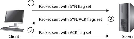
Figure 3-2 TCP three-way handshake
EXAM TIP In a common denial of service (DoS) attack known as a SYN flood attack, the client withholds the third packet. The server is left with a half-open session consuming system resources while it waits for the third packet. However, instead of sending the third packet, the attacker floods the system with more SYN packets. Chapter 5 covers DoS attacks in more depth.
If another protocol requires guaranteed delivery, it uses TCP. For example, IP doesn’t include the ability to ensure guaranteed delivery. Instead, IP uses TCP to provide the guaranteed delivery. If the protocol does not require guaranteed delivery, it uses UDP.
UDP
UDP is a connectionless protocol. Instead of checking to see whether a connection exists with another system before sending data, UDP simply sends it. Another way of thinking of this is that UDP gives a “best effort” to send the data, but it does not verify delivery. This could be like you sending a text or an e-mail to a friend to pass on some information. There’s a good chance your friend will receive the message, but you don’t have any automatic verification.
Many diagnostic protocols use UDP because they don’t need to establish a session when performing diagnostic tests. You’ll also see UDP used in simpler protocols such as Trivial File Transfer Protocol (TFTP), a simple, streamlined version of File Transfer Protocol (FTP). TFTP sends small files such as configuration files to network devices. FTP uses TCP, but TFTP uses UDP. UDP is also common with streaming data such as streaming audio or video. With streaming data, it’s acceptable to lose some bits occasionally here and there. For example, a streaming video file may hiccup occasionally when some bits are lost, but the overall file still plays.
TIP The terms connection-oriented and connectionless have nothing to do with a wired or wireless connection. Instead, they refer to the logical nature of a connection. TCP ensures both sides can communicate before starting a session. UDP simply sends the data without checking to see whether a logical connection exists.
The Session Layer (Layer 5)
The Session layer establishes and maintains sessions between applications or software processes on the local and remote systems. It keeps the session information for one application separate from the session information from other applications. Remote Procedure Call (RPC) is one of the few protocols that operates directly on this layer. Applications can use RPC to request a service from an application running on a different computer.
Data traveling on the application, presentation, and session layers is packaged and named protocol data units (PDUs).
The Presentation Layer (Layer 6)
The Presentation layer standardizes data presentation for the application layer. It translates data using standards such as American Standard Code for Information Interchange (ASCII), Extended Binary Coded Decimal Interchange Code (EBCDIC), Joint Photographic Experts Group (JPEG), Moving Picture Experts Group (MPEG), and so on. Some data encryption and decryption occurs at this layer. Additionally, data can be compressed and decompressed at this layer for better network performance.
The Application Layer (Layer 7)
Network applications use the Application layer to implement specific user applications. This layer provides the services needed for applications that communicate across a network.
The Application layer supports many additional security features. These include authentication, access control with mechanisms such as permissions, encryption for confidentiality, hashing for integrity, and the use of digital signatures for nonrepudiation.
TIP Chapter 14 covers many cryptographic topics, including encryption, hashing, and digital signatures.
Comparing the OSI and TCP/IP Models
The Defense Advanced Research Projects Agency (DARPA) created the TCP/IP Model. It has a similar goal as the OSI Model—to provide a common framework for connecting multiple computers together. Request for Comments (RFC) 1122 and 1123 identify the TCP/IP Model with four layers that map to the OSI layers. Some documentation identifies the TCP/IP Model with five layers, but the RFCs showing four layers are authoritative. Figure 3-3 compares the OSI Model to both four- and five-layer TCP/IP Models.
Figure 3-3 TCP/IP Models compared to the OSI Model
Looking at the four-layer TCP/IP Model, you can see that the upper-three layers of the OSI Model map directly to the Application layer of the TCP/IP Model. The OSI Transport layer maps to the TCP/IP Transport layer (also known as the Host or Host-to-Host layer). The OSI Network layer maps to the TCP/IP Internet layer. Finally, the OSI Data Link and Physical layers map to the TCP/IP Link layer (also known as the Network Interface or Network Access layer). Documentation that shows five layers typically names the bottom-four layers the same as they are on the OSI Model. In essence, they perform the same tasks.
EXAM TIP Although RFCs 1122 and 1123 identify the TCP/IP Model with four layers, some references identify it with five layers. The TCP/IP Model is also called the TCP Model and the DoD Model. DoD is an acronym for the Department of Defense.
Understanding Network Topologies and Relationships
The network topology refers to the layout of a network. It includes items you can touch such as cables and network devices. The primary configuration you’ll see in most networks today is star, but you may also see bus, tree, token ring, and mesh configurations. In addition to understanding the topologies, it’s important to understand how Ethernet fits into the mix.
Ethernet
The IEEE 802.3 family of standards defines Ethernet. It is the most widely used standard for local area networks (LANs). A working group drafted the first standard in 1973, and the Institute of Electrical and Electronics Engineers (IEEE) has steadily released updates since then. For example, Gigabit Ethernet over twisted pair (802.3bp) and 10 Gigabit Ethernet over fiber (802.3ae) define the standards used for sending data over a network with progressively higher bandwidths.
TIP Modifications to the 802.3 standard are identified with lowercase letters such as 802.3a, 802.3b, and so on. While the standard alphabet has only 26 letters, there have been more than 26 modifications to the 802.3 standard. The modification after 802.3z is 802.3aa. Similarly, the modification after 802.3az is 802.3ba.
When discussing Ethernet, it’s important to understand Carrier Sense Multiple Access (CSMA) and collisions. A collision occurs when two devices try to communicate at the same time over the same medium. Because both devices are sending traffic, the data from both systems collides with each other and none of the data is readable. There are two ways of dealing with collisions if the systems are using the same wire for sending and receiving: detecting them or avoiding them.
CSMA/CD
Ethernet networks support Carrier Sense Multiple Access/Collision Detection (CSMA/CD). In CSMA/CD, each of the devices on the network can detect collisions. As soon as a device detects a collision, it sends a signal on the wire letting all other systems know that a collision occurred. Each device then waits a random amount of time before resending.
However, most switches and computers today use full-duplex connections. In other words, the cable connecting a switch and a computer includes two sets of wires, with one set of wires used for receiving and another set of wires used for transmitting. If full duplex is used, and each device is connected directly with only one other device, collisions don’t occur on this cable.
Unfortunately, some older devices still use half duplex. In a half-duplex connection, a single set of wires is used for both transmitting and receiving. It’s possible for one system to transmit at the same time as another device is transmitting, resulting in a collision. Ethernet supports CSMA/CD for backward compatibility.
CSMA/CA
In Carrier Sense Multiple Access/Collision Avoidance (CSMA/CA), systems listen before transmitting data. If they sense that other systems are transmitting data, they wait a random amount of time to check again before sending traffic. Wireless networks such as 802.11 networks use CSMA/CA.
Wireless networks also support Request To Send (RTS) and Clear To Send (CTS) to negotiate traffic. When a computer wants to transmit data, it sends out the RTS signal. The destination replies with a CTS signal and waits for the transmission.
Bus Topology
In a bus configuration, all the hosts are connected together via a single shared cable connection as shown in Figure 3-4. Earlier networks commonly used the bus configuration because it was easy to set up. However, it is very difficult to troubleshoot, so you won’t see it used to connect entire networks together today.
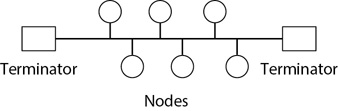
Figure 3-4 Bus configuration
The cable used in a bus configuration is typically coaxial cable. This is similar to a cable used for cable television. T connectors connect each computer on the network. The cable connects to one end of the T, the base of the T connects to the computer, and the other end of the T goes to the next computer.
Notice that each end of the bus includes a terminator. When an electrical signal travels down a wire, it will reflect back when it reaches the end unless the wire has a terminator. This reflected signal corrupts other data transmissions on the bus. The terminator is a connector that prevents this signal reflection. Removing the terminator effectively takes the entire bus network down.
Consider how the computers are connected with a T connector to the main bus. If any one of these T connections is disconnected, you no longer have a single bus with two terminators. Instead, you have two buses, and each one only has a single terminator instead of two terminators. In other words, none of the computers will be able to communicate on the network.
If you only have three or four computers on your network, you can probably locate the problem relatively easily. However, if the network includes several hundred computers, it can take quite a long time to discover the source of the problem.
Older Ethernet standards for bus configurations include 10Base2 (ThinNet) and 10Base5 (ThickNet). These use thin and thick coaxial cables, respectively, for bus configurations.
EXAM TIP Bus networks are expensive to maintain because of how difficult it is to troubleshoot problems. A single break in the cable takes down the entire network, reducing availability.
Star Topology
In a star configuration, all the devices are connected to a central device such as a hub or switch, as shown in Figure 3-5. When drawn this way, it is reminiscent of a star, which is how it gets its name.

Figure 3-5 Star configuration

NOTE Many network diagrams are drawn like a bus configuration diagram but are actually configured in a star. In other words, network diagrams don’t indicate whether the network is configured as a bus, star, or token ring. Instead, they show the relevant components, such as the routers and networks.
A star configuration is much more common in typical computer networks today. Additionally, the devices typically connect with UTP or STP cable. UTP and STP cables use RJ-45 connectors. Common twisted pair cable categories are Cat 5e, 6, and 6a. Cat 5e cable supports speeds up to 1 gigabit and Cat 6 and 6a cables support speeds up to 10 gigabit. The maximum length of these cables is limited to 100 meters (about 330 feet).
A typical star configuration uses a switch as the central component, and computers connect to the switch as nodes in the star with UTP or STP cable. Each of the computers communicates with other computers on the network via the switch. Network devices include components to terminate connections automatically, so external terminators are not required in a star configuration as they are in a bus configuration.
Networks configured in a star are much easier to troubleshoot than a bus network. If someone disconnects a cable from a single computer, only that computer is affected. All the other computers still work. However, compared to the bus configuration, you need much more cable. Each device uses a separate cable from it to the network device, which is typically stored in a secure location such as a locked wiring closet or a server room.
The central device in a star configuration could be a hub, but most organizations have replaced hubs with switches. When a hub is used, all traffic that goes in one port goes out all the other ports of the hub. An attacker could install a protocol analyzer (sniffer) on any computer connected to the hub and capture all the data going through the hub. However, when organizations replace hubs with switches, the only unicast traffic that will reach the attacker’s computer is traffic that is directly addressed to or from the attacker’s computer. This improves network efficiency by limiting traffic to computers, and it reduces the potential success of sniffing attacks.
It is possible to configure most switches with a mirrored port. This sends a copy of all traffic through the switch to the mirrored port for monitoring. If an attacker has physical access to the switch, the attacker can connect to the monitoring or mirrored port and sniff all the traffic. Because of this, organizations keep switches in secure areas, such as in a locked wiring closet or a locked server room. Securing a switch in a wiring closet or server room provides physical security.
Ethernet standards for star configurations use twisted pair cable such as 10Base-T, 100Base-TX, 1000Base-T, and 10GBase-T supporting bandwidths of 10 Mbps, 100 Mbps, 1 Gbps, and 10 Gbps, respectively.
Tree Topology
A tree topology is a combination of a bus topology and a star topology. Instead of connecting multiple computer nodes in the bus configuration, it connects multiple star networks along a type of a bus network.
Because all of the star networks are connected to each other via the bus network, a break in the bus network disconnects the star networks from each other. However, a break in the bus does not affect communication within any of the individual star networks.
Token Ring Topology
IEEE 802.5 defines token ring networks. In a token ring network, each device is connected together in a ring. Additionally, the ring includes a logical token that controls when computers can communicate. This prevents collisions because computers can send traffic on the network only when they have the token.
For example, consider a group of five people in a room sitting in a circle. Each person can talk, but only while holding a piece of paper identified as a token. Each person takes turns talking, and when they are done, they pass the token to the next person in the ring.
Figure 3-6 shows two diagrams of a token ring. The diagram on the left shows what the original token ring networks looked like. Each computer is connected to two other computers in the ring, and the computers pass the token around the network. If a computer has the token, it can send traffic on the network. However, if any of the computers fails or is disconnected from the network, it breaks the ring. No other computers will be able to communicate.
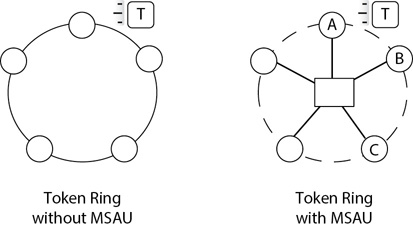
Figure 3-6 Token ring configuration
The configuration on the right includes a multistation access unit (MSAU), also called a media access unit (MAU). The traffic still flows logically in a circle, but it goes through the MSAU. For example, Computers A, B, and C aren’t connected directly to each other, but instead they are connected to the MSAU. Traffic passes from Computer A to the MSAU, then to Computer B, back to the MSAU, and then to Computer C. If a computer fails, or a connection between the MSAU and a computer breaks, the MSAU senses the failure and bypasses the computer. In other words, a single failure does not take down the entire network.
Token ring networks don’t scale well. Adding more computers significantly reduces performance. If a token ring has five computers, each computer has the token for about 20 percent of the time. However, if the token ring has 100 computers, each computer has the token for only about 1 percent of the time. Traffic can slow to a crawl.
An extension of token ring networks is the Fiber Distributed Data Interface (FDDI) standard. It uses fiber-optic connections instead of copper connections and thus supports much higher bandwidth. It also uses dual rings. The second ring is used only when the system detects an error in the primary ring. Conventional token ring networks support speeds up to 16 Mbps. However, FDDI token rings support speeds up to 100 Mbps over distances as far away as 120 miles.
Mesh Topology
Mesh topologies provide redundancy with multiple connections, providing the highest availability of any of the topology methods. A full mesh topology connects every computer or node in a network with every other node. A partial mesh topology provides multiple redundant connections but doesn’t connect every node with every other node in the network. In either a full mesh or a partial mesh, computers in the network are still able to communicate with each other, even if some connections fail.
Figure 3-7 shows two examples of full mesh topologies. The one on the left has four nodes and six connections. The one on the right has five nodes and ten connections.
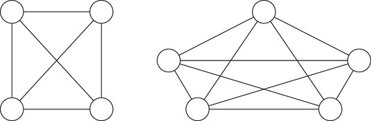
Figure 3-7 Mesh topology
Notice how adding a single node requires the addition of multiple new connections. You can calculate the number of connections needed in a mesh topology with the formula n(n – 1)/2, where n is the number of computers. For example, with four computers, n=4 and the formula is
• 4(4 – 1)/2
• 4 × 3/2
• 12/2 = 6
Add another computer and the calculation is 5(5 – 1)/2, or 10 connections. Six computers require 15 connections. Each of these connections adds costs, so you’ll rarely see full mesh topologies in a regular network. However, there are many instances where designers combine mesh topologies with another topology to create a partial mesh. This partial mesh topology has multiple connections to provide a high level of redundancy, but it doesn’t connect every single computer with every other computer in the network.
Network Relationships
Network relationships refers to how computers connect with each other. The two common network relationship types are peer-to-peer and client-server.
In a peer-to-peer network, systems are independent of each other and authentication is decentralized. As an example, you can have a home network with four computers and a printer connected with both wired and wireless connections. You can log on to your computer, other people in your home can log on to their computers, and everyone can print to the networked printer. In a Microsoft environment, this is referred to as a workgroup. Workgroups are typically used for smaller networks.
It’s also possible to share folders on individual computers in a peer-to-peer network. However, these are typically accessible to anyone and everyone that has access to the workgroup. If you share a folder on your computer, you can limit access. You’ll need to create another account on your computer and limit the access to this new account. Anyone that knows the credentials for this new account can access the share, but this requires other users to know multiple usernames and passwords.
In a client-server network, a server holds accounts and provides centralized authentication. In a Microsoft network, this is called a domain. A domain controller holds user accounts, and when users log on, they log on to their computer (and the domain) using their domain account. Within a domain, it’s common to create groups to organize users. For example, a group named HelpDesk can be used to organize employees working on the help desk. It’s then possible to share folders and grant access to the folders to the HelpDesk group.
Reviewing Basic Protocols and Ports
The TCP/IP protocol suite consists of a full range of protocols used to connect computers on the Internet and on most internal networks. You don’t need to know the details of all the protocols, but you should understand the basic function of many of them. The following sections list some common protocols along with their acronyms and a brief explanation of the protocol.
It’s also important to know the logical port numbers for many of the protocols. The “Mapping Well-Known Ports to Protocols” section later in this chapter describes the use of these ports in more detail and includes a table mapping some well-known ports to protocols. However, I’ve also listed the relevant port numbers in the protocol descriptions in case you turn to only that section for a description of the protocol.
A core step in hardening a server, or making it more secure from the default configuration, is to remove all unneeded protocols and services. It’s important to know what protocols are required and what protocols are optional when securing any system. Consider a server that is not running FTP. If an attacker tries to attack this server using a known FTP exploit, it simply won’t work because FTP is not installed on the server.
On the other hand, consider a server that is running 100 different protocols. It is now susceptible to attacks on each of these protocols. By removing unneeded protocols, you reduce the attack surface of the server. Once you understand some basics about protocols, you can determine if a server needs specific protocols or if you can disable or remove them.
Figure 3-8 identifies the layers of the TCP/IP and OSI models where several protocols reside. The following pages include descriptions of these protocols.
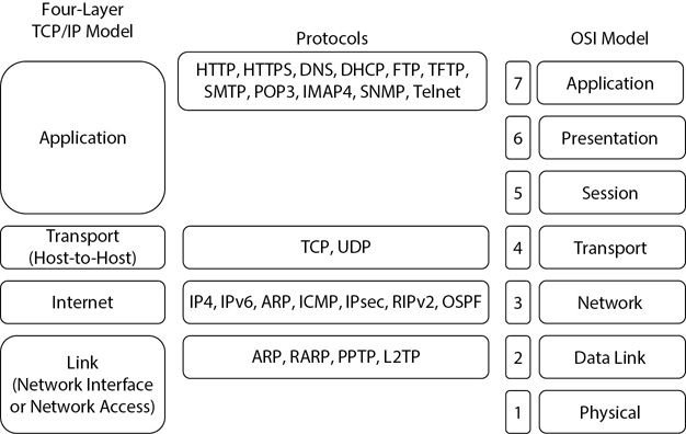
Figure 3-8 Mapping protocols to the OSI and TCP/IP models
Comparing IPv4 and IPv6
IP is the protocol used for addressing. Currently, both IPv4 and IPv6 addresses are in use on the Internet and in many internal networks. An IPv4 address uses 32 bits, but is typically displayed in dotted decimal format (such as 192.168.1.1), where each decimal number represents 8 bits.
An IPv6 address uses 128 bits, and is displayed with hexadecimal characters instead of decimal numbers. When the full IPv6 address is displayed, it includes eight groups of four hexadecimal characters separated by seven colons like this:
fe80:0000:0000:0000:045d:2376:095f:0075
NOTE RFC 5952 states that IPv6 hexadecimal characters such as a, b, c, d, e, and f must be represented in lowercase. This eliminates potential problems when systems search for an IPv6 address.
Two methods used to shorten the displayed address include omitting leading zeros and using zero compression. When omitting leading zeros, the address looks like this:
fe80:0:0:0:45d:2376:95f:75
Even though this omits leading zeros, it’s just for display. The actual IPv6 address still includes 128 bits.
Zero compression replaces a contiguous string of zeros with a double colon like this:
fe80::45d:2376:95f:75
Even though you don’t see seven colons, or eight groups, this is also just for display. The actual IPv6 address still includes 128 bits.
Dynamic Host Configuration Protocol
A Dynamic Host Configuration Protocol (DHCP) server uses DHCP to assign TCP/IP configuration information to DHCP clients. This includes IP addresses, subnet masks, addresses of DNS servers, and much more. Many people shorten the definition of DHCP to say that it simply assigns IP addresses, but that is not completely accurate. There are close to 70 different options that a DHCP server can assign.
DHCP uses four primary messages between the client and the DHCP server:
• DHCPDiscover The DHCP client broadcasts this message when it is looking for a DHCP server that can provide the IP address and other configuration information.
• DHCPOffer DHCP servers that have IP addresses to offer for the client’s subnet respond by broadcasting an offer. The message includes information such as the offered IP address, subnet mask, the IP address of the DHCP server making the offer, and any additional information configured on the DHCP server.
• DHCPRequest The DHCP client responds to the first offer it receives with a broadcast request to use the offer. This message includes the IP address of the DHCP server that made the offer.
• DHCPAck The DHCP server responds with a DHCP acknowledge message. At this point, the DHCP server re-serves that IP address to the DHCP client. When the DHCP client receives the information, it configures itself with the IP address and other TCP/IP configuration information.
DHCP uses UDP ports 67 and 68. The DHCP client sends traffic out on port 67 and receives answers on port 68. The DHCP server sends traffic on port 68 and receives traffic on port 67.
NOTE DHCP isn’t limited to only running on a server. Many wireless routers include the DHCP service, which greatly simplifies the configuration of a wireless network.
Address Resolution Protocol
The Address Resolution Protocol (ARP) resolves IP addresses to MAC (or physical) addresses. The MAC address is 48 bits displayed as 12 hexadecimal numbers (such as 6c-62-6d-ba-73-6c). It is assigned to the NIC and uniquely identifies the computer. Systems use the MAC address when connecting to other computers on the same subnet.
From a big picture perspective, systems use the IP address to get packets from one subnet to another on the Transport layer. Once the packet arrives on the destination subnet, systems use the MAC address to get the frame to the destination computer on the Data Link layer.
ARP broadcasts a datagram that essentially asks all the computers on the subnet, “Who has this IP? If it’s you, tell me your MAC address.” The computer with that IP address responds with its MAC address.
Reverse Address Resolution Protocol (RARP) works just the opposite of ARP. A client has a MAC address and uses RARP to get an IP address. You can think of this as a simplified version of DHCP. It provides the client with some TCP/IP configuration information, but doesn’t have the full capabilities of DHCP.
The Bootstrap Protocol (BootP) is similar to RARP in that it provides clients with IP addresses. However, it goes beyond just getting an IP address and can be used to retrieve a bootable image for diskless clients.
EXAM TIP ARP resolves IP addresses to physical or hardware addresses (MAC addresses). RARP allows a client with a MAC address to get an IP address. BootP allows a diskless client with a MAC address to get an IP address and retrieve a bootable operating system image.
Network Discovery Protocol
IPv6 uses the Network Discovery Protocol (NDP) instead of ARP to resolve IPv6 addresses to the IPv6 version of MAC addresses. IPv4 uses a 12-hexadecimal number (48 bits) for MAC addresses. IPv6 uses a 64-bit modified EUI-64 address instead of the IPv4 MAC address. EUI is an acronym for Extended Unique Identifier.
NDP does more than just resolve IPv6 addresses to EUI-64 addresses. Some of the tasks include
• Automatically configures nodes
• Discovers other nodes on the network
• Locates available routers on the network
• Detects duplicate addresses on the network
Domain Name System
A Domain Name System (DNS) server provides name resolution services. More specifically, DNS resolves host names to IP addresses as its primary function. For example, a DNS client can query the DNS server with the host name of a computer, and the DNS server replies with the host’s IP address.
DNS uses a hierarchical naming system with a distributed database to provide responses to clients. Any single DNS server doesn’t know the IP address of all the systems on the Internet. However, by querying different servers in the hierarchy, it’s possible to discover the IP address of any system with a public IP address.
Thirteen root servers at the top of the hierarchy know the IP addresses for top-level domain DNS servers. Top-level domains include .com, .gov, .edu, .net, and so on. These top-level domain DNS servers know the IP address of second-level DNS servers within the same domain. For example, a .com DNS server knows the IP address of authoritative DNS servers in the mcgraw-hill.com domain. Second-level domain DNS servers know the IP address of third-level DNS servers within the same domain.
The distributed database includes several different types of records to provide different responses. Some of the records in a DNS database are
• A (host) record Resolves a host name to an IPv4 address
• AAAA (host) record Resolves a host name to an IPv6 address
• PTR (pointer) record Resolves an IP address to a host name
• MX (mail exchange) record Identifies a mail server
• CNAME (canonical name or alias) record Allows a system to be known by different names, or aliases. For example, a web server can be named Web1 but also respond to a name of www.
Berkeley Internet Name Domain (BIND) is a version of DNS software that runs on UNIX systems. It is freely available and runs on many DNS servers on the Internet. Microsoft networks running in internal organizations commonly use Microsoft’s version of DNS.
When clients query DNS for name resolution, DNS uses UDP port 53. However, when DNS servers transfer data between each other, they use TCP port 53.
Domain Name System Security Extensions (DNSSEC) adds security to DNS systems. DNSSEC is a suite of extensions that validates DNS responses with a Resource Record Signature (RRSIG), which is similar to a digital signature. The digital signature provides authentication of the response so that DNS clients know that the data hasn’t lost integrity. This helps prevent DNS cache poisoning attacks. Chapter 14 provides more information on digital signatures.
EXAM TIP DNS uses a hierarchical structure with a distributed database to provide name resolution services. BIND is commonly used on the Internet, while Microsoft DNS is often used within a Microsoft internal network. DNSSEC helps prevent against DNS cache poisoning attacks.
Internet Control Message Protocol
The Internet Control Message Protocol (ICMP) is used with many diagnostic protocols such as ping, pathping, and tracert to check or verify the health of a network. For example, if you enter ping and an IP address (such as ping 192.168.1.10) on a Windows system, ping sends four packets to the IP address. If firewalls aren’t blocking ICMP, the host with that IP address will reply with four ping packets. Other operating systems, such as Linux and UNIX, will continue to send ping requests until the user presses CTRL-C.
TIP UNIX and Linux systems use traceroute instead of tracert. While there are many similarities between the two commands, traceroute uses UDP instead of ICMP.
Attackers often use ICMP in DoS attacks, so firewalls frequently block ICMP traffic. In other words, a server may be operational, but a ping to that server will fail due to a firewall blocking ICMP traffic.
Internet Group Message Protocol
The Internet Group Message Protocol (IGMP) is used for IPv4 multicasting, where data is sent from one computer to multiple computers at the same time. Computers join a multicast group with a multicast address (in the range of 224.0.0.0 through 239.255.255.255) to receive the multicast transmissions.
TIP IPv6 does multicasting differently than IPv4. IPv6 uses Multicast Listener Discovery (MLD) with ICMPv6 messaging instead of IGMP.
You can compare multicasting used with IGMP to unicast and broadcast messages:
• Unicast Systems send traffic from one computer to one other computer.
• Broadcast Systems send traffic from one computer to all other computers on the subnet. Switches pass broadcast traffic, but routers do not pass broadcast traffic, so broadcast traffic only goes to computers on the same subnet.
• Multicast Systems send traffic from one computer to multiple computers in the network. Routers pass multicast traffic, so multicast transmissions can reach computers on multiple subnets within the network. Many audio and video streaming applications use multicast, and multicast uses UDP.
Simple Network Management Protocol
The Simple Network Management Protocol (SNMP) is commonly used to manage network devices (such as routers and layer 3 switches) on a network. SNMP agents on the network devices send traps (errors) and other notifications back to a central server running SNMP management software. Additionally, a server hosting SNMP management software can use SNMP to configure the network devices remotely.
SNMPv1 and SNMPv2 had several security flaws, but SNMPv3 provides significant improvements. For example, client authentication in SNMPv1 was handled with a community string, and the default community was “public” in SNMPv1 and SNMPv2. However, SNMPv3 introduced several security enhancements. SNMPv3 uses encryption to achieve confidentiality, verifies the integrity of the packets, and includes authentication to verify that the data is from a known entity. SNMP agents receive data on UDP 161 and send traps and notifications on UDP port 162. When using Transport Layer Security (TLS) to encrypt data, Secure SNMP uses TCP ports 10161 and 10162.
When SNMP is active on a network, internal routers will pass SNMP traffic. However, it’s common to block all SNMP traffic at the boundary of the private network with the Internet. This prevents attackers from accessing internal devices using SNMP.
File Transfer Protocol
File Transfer Protocol (FTP) is used to transfer files from one system to another. Some organizations host FTP servers that allow individuals to upload and download data. The FTP server provides a simple storage location for people located in different areas of the world. One benefit of FTP is that it supports authentication in the form of a username or password, but administrators can also configure FTP to support anonymous connections. FTP uses TCP ports 20 and 21.
Trivial FTP (TFTP) was mentioned briefly earlier in the chapter in the “UDP” section. TFTP is a stripped-down version of FTP that provides very basic capabilities. It doesn’t support authentication and doesn’t use TCP to establish a session. However, it is very useful when transferring configuration files to and from network devices. TFTP uses UDP port 69.
EXAM TIP FTP supports authentication and is commonly used to transfer large files across a network. FTP uses TCP ports 20 and 21. TFTP does not support authentication and is commonly used to transfer small configuration files to and from network devices. TFTP uses UDP port 69. Both transfer data across a network in cleartext.
Both FTP and TFTP have significant security issues. Data sent across the network using FTP and TFTP is sent in cleartext. Anyone with a sniffer can easily capture the data and read the contents of the FTP packets. This includes the username and password used to log on to an FTP server, and the data.
Secure FTP (SFTP) uses Secure Shell (SSH) to encrypt FTP traffic. SFTP functions similarly to FTP, but the encryption prevents sniffing attacks from capturing data in cleartext. FTP Secure (FTPS) is another protocol that encrypts FTP sessions. It uses Transport Layer Security (TLS) for encryption.
Telnet
Telnet is a legacy protocol used to interact with a remote system using text-based commands. For example, a server with Telnet enabled will accept connections from a system running a Telnet client. When the client connects, the user can enter commands from a Telnet command prompt. Telnet uses TCP port 23.
Although Telnet used to be much more popular, especially in UNIX and UNIX derivatives such as Linux, you will rarely see it in use today. Telnet sends data (including login credentials) across the network in cleartext, which attackers can capture and read using a sniffer. Once attackers have the credentials, they can log on to the Telnet server and launch additional attacks.
Secure Shell
Secure Shell (SSH) is an encryption protocol that can create a secure session between two computers. It is used to encrypt other protocol traffic, such as FTP (called Secure FTP or SFTP) and Secure Copy (SCP), and can replace many protocols such as Telnet, rlogin (remote login), rsh (remote shell), and rexec (remote execute). SSH also supports secure port forwarding. SSH uses TCP port 22.
Many Linux and UNIX systems support rlogin, a utility that allows users to log in to a remote computer. Similarly, many Linux and UNIX systems support rsh and rexec, which allow users to execute commands on remote computers. However, these commands send data across a network in cleartext, representing significant risks.
SSH provides several security services. It uses asymmetric and symmetric encryption to provide confidentiality, and hashing techniques to provide integrity. SSH also supports mutual authentication, where both the client and the server prove their identity within an SSH authenticated tunnel. RFCs 4251, 4252, 4253, and 4254 document the SSH protocol.
EXAM TIP SSH can encrypt other protocols such as FTP (as SFTP). It is a more secure alternative than older protocols such as Telnet, rlogin, rsh, and rexec that send data across a network in cleartext. SSH uses a combination of asymmetric and symmetric encryption for confidentiality, hashing for integrity, and an SSH authenticated tunnel for authentication. SSH uses TCP port 22.
Hypertext Transfer Protocol and Hypertext Transfer Protocol Secure
Hypertext Transfer Protocol (HTTP) is the common protocol used to transfer web pages over the Internet. Most web browsers use HTTP by default. For example, you could type in the address of a site such as www.mcgraw-hill.com and it will default to http://www.mcgraw-hill.com. HTTP uses TCP port 80.
NOTE Some web browsers hide “http://” in the address bar so you may not see it. However, if you copied the URL and pasted it into a document, you would see that it is including http:// even if you don’t type it in the address bar.
HTTP Secure (HTTPS) is an encrypted form of HTTP and is commonly used when processing e-commerce transactions over the Internet. Transport Layer Security (TLS) encrypts the HTTPS sessions in almost all Internet applications. Secure Sockets Layer (SSL) encrypted HTTPS originally, but due to known vulnerabilities, it has been deprecated and is not recommended for use. Data encrypted within HTTPS is not readable by anyone who is not involved in the HTTPS session. HTTPS uses TCP port 443.
Transport Layer Security and Secure Sockets Layer
Transport Layer Security (TLS) is a popular encryption protocol used to encrypt different types of traffic. You most often see TLS used to encrypt HTTP traffic (as HTTPS). However, other implementations also use TLS. For example, some VPNs use TLS to encrypt tunnel traffic.
Transport Layer Security (TLS) is the designated replacement for Secure Sockets Layer (SSL), and is based on SSL. Although the acronym HTTPS historically has meant that SSL is encrypting an HTTP session, current HTTPS sessions use TLS. Chapter 14 describes the process used by TLS when encrypting HTTPS traffic.
TIP SSL is vulnerable to POODLE (Padding Oracle On Downgraded Legacy Encryption) attacks and no longer recommended for use. Personnel from Google documented this attack in late 2014, which prompted organizations still using SSL to switch to TLS.
IT personnel often debate the actual OSI layer where these protocols operate. RFCs typically provide a definitive answer, but both TLS and SSL are layered protocols, meaning that they operate on different layers. RFC 6101 is a historic RFC that describes SSL. RFCs 2246, 4346, 5246, and 6176 formally define TLS. The following list describes operations performed by TLS on different layers:
• Transport layer TLS creates the initial connection on the Transport layer (layer 4). With the name Transport Layer Security, it’s implied that TLS operates on the Transport layer.
• Session layer The Handshake Protocol within TLS operates on the Session layer (layer 5) when negotiating details for the TLS session. This includes details such as what specific encryption algorithm to use.
• Application layer The TLS Record Protocol within TLS operates on the Application layer (layer 7). It provides confidentiality with an encryption algorithm and integrity with a hashing algorithm.
Network File System
Network File System (NFS) allows computers running different operating systems to access and share files over the network. NFS is an open standard created by Sun Microsystems. It allows users running UNIX (and UNIX derivatives such as Linux) to access files on Microsoft systems. Similarly, NFS allows users running Microsoft systems to access files on UNIX-based systems.
Routing Protocols
As mentioned previously, routing occurs at the Network layer. Routers identify the best path for a packet to take based on information it knows about the network. It’s possible to enter routing information manually in a smaller network, but for larger networks, the routers communicate with each other using a routing protocol. The two primary routing protocols used on internal networks are Routing Information Protocol version 2 (RIPv2) and Open Shortest Path First (OSPF).
Although RIPv2 works well, it can generate a lot of traffic and doesn’t scale well. In general, RIPv2 is good for smaller networks, while OSPF works better in larger networks. RIPv2 is very easy to enable and configure on routers, while OSPF takes a little more effort. Both RIPv2 and OSPF operate on the Network layer of the OSI Model.
E-mail Protocols
You should know about three primary e-mail protocols when preparing for the SSCP exam: Simple Mail Transfer Protocol (SMTP), Post Office Protocol version 3 (POP3), and Internet Message Access Protocol version 4 (IMAP4).
Clients use SMTP to send e-mail to an e-mail server for delivery. Some clients receive e-mail from a POP3 server, and other clients access e-mail from an IMAP4 server. POP3 servers simply send the e-mail to the client when the client connects. Some POP3 servers delete the e-mail as soon as the client receives it. Other POP3 servers keep the e-mail for a preset time limit, or until the user deletes it off the server.
IMAP4 servers store e-mail on the server and allow users to organize the e-mail in folders. This allows users to access e-mail on multiple devices. As an example, e-mail downloaded to your smartphone can also be downloaded to your tablet device. Additionally, if you move an e-mail to a folder on one device, it will be moved to the same folder on all other devices configured to sync with the IMAP4 server.
Another advantage of IMAP4 over POP3 is that users can configure it to show only the headers. This allows users to screen some of the e-mail before downloading it to their system. In contrast, POP3 sends the entire contents to the client as soon as the client connects.
SMTP uses TCP port 25, POP3 uses TCP port 110, and IMAP4 uses TCP port 143. Each of these protocols supports encryption with SSL or TLS. SMTP with SSL/TLS uses TCP port 465, IMAP4 with SSL/TLS uses TCP port 993, and POP3 with SSL/TLS uses TCP port 995.
With the overwhelming amount of spam and phishing attacks, IMAP4 is an appealing alternative used by many e-mail servers on the Internet. Users can often tell by the sender e-mail address or the subject line whether they want to open the e-mail or just delete it. For example, I’d love to actually win $1,500,000 just because I have a Gmail account, but when I see the subject line saying, “Your e-mail ID has won $1,500,000,” I know it’s a phishing attempt and I simply delete the message to eliminate the risk.
EXAM TIP Users send e-mail with SMTP over TCP port 25. Users receive e-mail with POP3 over TCP port 110 or IMAP4 using TCP port 143. IMAP4 allows users to manipulate the e-mail on the server, including organizing e-mail in folders.
Internet Protocol Security
Internet Protocol security (IPsec) provides security for IP traffic traveling over a network. It provides mutual authentication of systems, integrity, and confidentiality. Chapter 4 expands on IPsec, but as an introduction, IPsec has two primary components:
• Authentication Header (AH) AH provides authentication between the systems and verifies the integrity of the packets, but it does not encrypt the data. The header content is created from a hash of the packet with additional authentication data, and this hash is then encrypted to prevent tampering. The hash provides integrity. Systems identify AH packets with protocol number 51.
• Encapsulating Security Protocol (ESP) ESP encrypts the data and includes the same authentication services provided from AH. Data encrypted with ESP cannot be read if captured with a sniffer. Systems identify ESP packets with protocol number 50.
EXAM TIP Note that AH and ESP are identified with protocol numbers (not port numbers). The “Comparing Ports and Protocol Numbers” section later in this chapter identifies the differences. The IP header includes the protocol number field. Other protocol number values that aren’t associated with IPsec are as follows: ICMP is 1, IGMP is 2, TCP is 6, and UDP is 17.
Tunneling Protocols
Chapter 4 explores virtual private networks (VPNs) in greater depth. In general, a VPN provides access to a private network over a public network such as the Internet. Because traffic traverses a public network, potential attackers can access the data using a protocol analyzer or sniffer. A common method of protecting VPN traffic is to encapsulate it in a tunneling protocol and encrypt the encapsulated data.
Two common tunneling protocols are the Point-to-Point Tunneling Protocol (PPTP) and the Layer 2 Tunneling Protocol (L2TP). PPTP provides encryption, while L2TP relies on IPsec for encryption. Both operate on the Data Link layer. PPTP uses TCP port 1723 and L2TP uses UDP port 1701. TLS and IPsec can also be used as tunneling protocols. Chapter 4 explores these protocols in more depth.
Mapping Well-Known Ports to Protocols
There are a total of 65,536 TCP ports and 65,536 UDP ports. They are divided into three sections:
• Well-known ports (0 to 1023) These ports are assigned to widely used protocols by the Internet Assigned Numbers Authority (IANA).
• Registered ports (1024 to 49,151) These ports are also assigned by IANA, although most are not as widely used as the well-known ports.
• Dynamic (49,152 to 65,535) These ports are assigned dynamically by internal systems.
As an example of how ports are used, consider Figure 3-9. The client is using a web browser to connect to an organization’s internal web server. When the user clicks a link to connect to the web server, several things happen to retrieve a web page. To begin, the client creates a datagram and sends it to the web server.
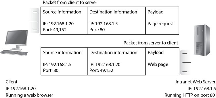
Figure 3-9 Using IP addresses and ports
The datagram includes the source and destination IP addresses and the source and destination ports. A web server has an IP address of 192.168.1.5 and uses TCP port 80 for HTTP, so the destination port is port 80. The client adds its IP address (192.168.1.20) as the source IP address and then identifies an unused port in the dynamic range and assigns it as the source port for this datagram. The user’s computer maps the source port to the user’s web browser application.
TCP/IP gets the datagram to the server using the destination IP address. Once the datagram reaches the server, the server uses the destination port to get the datagram to the correct protocol, service, or application that is servicing that port. In this example, the destination is port 80, which is the well-known port for HTTP. The server sends the datagram to the web server application servicing HTTP.
The web server then creates the web page and puts the data together to return the web page to the client. Because the source of the original packet was 192.168.1.20 with a port of 49,152, this now becomes the destination. Again, TCP/IP gets the packet to the client computer using the destination IP address.
When the client receives the packet, it identifies the destination port (49,152), which it previously mapped to the web browser application. The operating system sends the data to the web browser, which then displays it. It’s worth noting that some firewalls log the combination of the IP address and the port as a socket. For example, the packet from the client to the server would have a source socket of 192.168.1.20:49152 and a destination socket of 192.168.1.5:80.
Table 3-1 lists many common protocols and ports, along with some basic comments about the protocol.
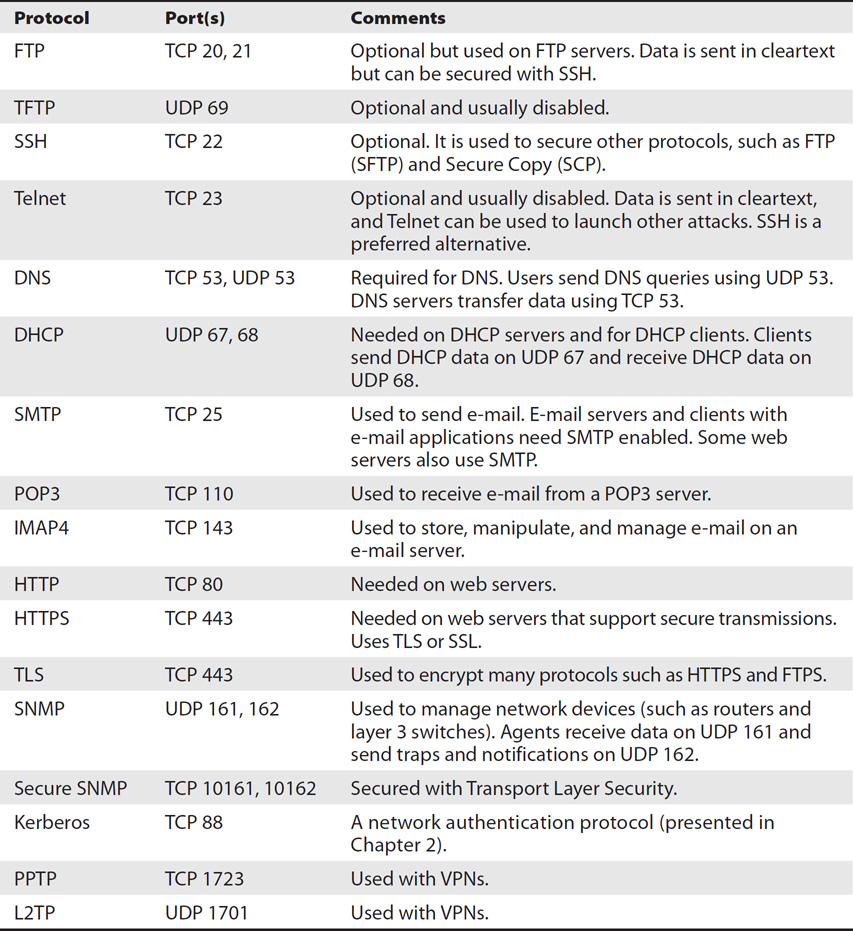
Table 3-1 Common Protocols and Their Port Numbers
Comparing Ports and Protocol Numbers
While some documentation indicates that ports are the same as protocol numbers, they are completely different. The first octet in TCP and UDP headers includes source and destination ports for TCP and UDP segments, respectively. As a reminder, TCP and UDP operate on the Transport layer of the OSI Model. IPv4 packets include protocol numbers in the Protocol field of the IPv4 header, and IPv6 packets include protocol numbers in the Next Header field of the IPv6 header. As a reminder, IPv4 and IPv6 operate on the Network layer of the OSI Model.
Table 3-2 lists common protocol numbers.
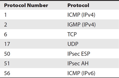
Table 3-2 Common Protocol Numbers
EXAM TIP Know the common ports and protocol numbers listed in Tables 3-1 and 3-2. Routers and firewalls use these to control traffic in and out of a network, so these are important security concepts to know.
Comparing Internetwork Trust Architectures
Computers are connected together using networks, and different types of networks provide different levels of trust. Generically, there are four types of networks: the Internet, an intranet, an extranet, and a demilitarized zone (DMZ, or perimeter network). Each of these can support different types of trust architectures, such as one-way trusts, two-way trusts, and transitive trusts.
Consider Figure 3-10 as you review the definitions of the first three different network types in the following list:

Figure 3-10 Comparing the Internet, an intranet, and a DMZ
• Internet The Internet is the public network accessible around the world. Any computer with access to the Internet can reach any other computer with access to the Internet. From a risk perspective, the Internet presents the most risk.
• Intranet An organization’s internal network is an intranet. From a risk perspective, an intranet presents the least amount of risk. An organization controls the resources on the internal network.
• DMZ When an organization wants to host resources on the Internet (such as with a web server, an e-mail server, or an FTP server), a common practice is to place these Internet-facing servers within a DMZ. The DMZ provides a layer of protection for the servers that would not be available if they were placed directly on the Internet. Although there are multiple methods for creating a DMZ, a common method is to use two firewalls, as shown in Figure 3-10. Another method is to create a multihomed firewall, using three or more NICs to create a separate screened subnet.
• Extranet and third-party connections An extranet is a network used to host resources via the Internet, but is accessible only to trusted third-party entities, as shown in Figure 3-11. For example, a company may have a partnership with another company and want to share resources with that partner through a web-based portal. Administrators at the first company can create an extranet to provide access to these resources, but restrict access to this network to only the trusted partner. Many organizations use federated access systems to provide single sign-on (SSO) capabilities to systems hosted in an extranet. Chapter 2 describes federated access in more depth.
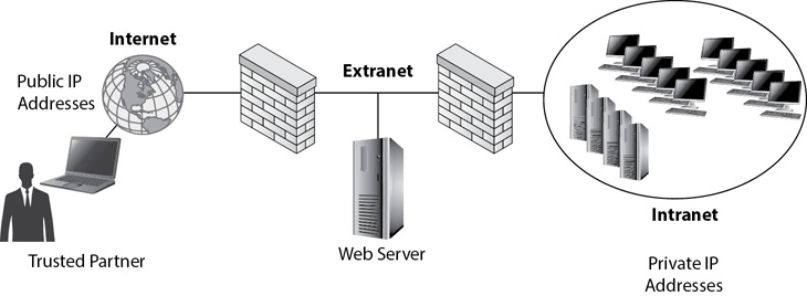
Figure 3-11 Comparing the Internet, an intranet, and an extranet
TIP Notice that the drawing representing an extranet (Figure 3-11) is very similar to the drawing for a DMZ (Figure 3-10). The difference is in the intent. Resources in a DMZ are available to any users on the Internet. Administrators configure an extranet so that resources are only available to trusted entities. An organization can host both a DMZ and an extranet.
Additionally, networks are identified with some other terms as follows:
• Personal area network (PAN) A small network centered on a person. For example, a person may have a cell phone paired with an earpiece and a microphone within a PAN.
• Local area network (LAN) A network that connects computers together in the same geographical location. A LAN is a single, well-connected network. It could be in a single room, a single building, or a group of buildings connected together with links of similar speeds.
• Metropolitan area network (MAN) A group of networks that are connected over a large area such as a university campus or even an entire city.
• Wide area network (WAN) A large network that connects computers across a large geographical area, such as in different cities. WAN links connect WANs together, and WAN links are typically slower than the links within individual LANs.
Comparing Public and Private IP Addresses
You may have noticed in Figures 3-10 and 3-11 that the Internet included public IP addresses, while the intranet included private IP addresses. Public IP addresses are used only on the Internet, and private IP addresses are used within an organization. A public IP address is accessible from any other public IP address. In other words, any computer (or any attacker) with access to the Internet from anywhere in the world can access another computer on the Internet because they both have public IP addresses.
Every public IP address must be unique. No two computers can be assigned the same public IP address. In contrast, private IP addresses must be unique only within an organization. For example, all the IP addresses used by McGraw-Hill in its network are unique within the McGraw-Hill network. However, (ISC)2 can use the same private IP addresses as McGraw-Hill because both companies use these IP addresses internally.
It’s common for IP addresses within the DMZ or within an extranet to have public IP addresses. However, it’s also possible to configure the firewalls to forward traffic to servers within a DMZ or extranet and configure these servers with private IP addresses.
RFC 1918 lists the IPv4 addresses reserved for private networks. They are as follows:
• 10.0.0.0 through 10.255.255.255.255 A very large address space with enough addresses for large organizations
• 172.16.0.0 through 172.31.255.255 A medium-sized address space
• 192.168.0.0 through 192.168.255.255 A smaller address space for smaller organizations
EXAM TIP Private IP addresses are not routable on the Internet. If traffic does reach the Internet with a private source or destination IP address, routers on the Internet drop it.
RFC 4193 lists the IPv6 addresses reserved for private networks. They are identified as unique local IPv6 unicast addresses (or local unicast addresses). They have a prefix of fc00::/7, which is a little misleading.
The /7 in fc00::/7 identifies the first seven bits in the address. A hexadecimal f is binary 1111, and a hexadecimal c is binary 1100. If only the first seven characters are used, it is 1111 110x, with x being the eighth bit. However, RFC 4193 specifies that the eighth bit is always a 1 (although this may change in the future), so the first eight characters of a unique local address are 1111 1101 or fd. In other words, it’s technically accurate to say that the link local address starts with fc00::/7, but in practice, you’ll actually see link local addresses that start with fd (using a hexadecimal d instead of a hexadecimal c).
Using NAT
The Internet has public IPv4 addresses, and internal networks have private IPv4 addresses. However, users with private IPv4 addresses can still access the Internet. Network Address Translation (NAT) provides a mechanism that allows this to happen. NAT is an additional service running on a system at the boundary between the Internet and an internal network.
Consider Figure 3-12. It shows an intranet with private IP addresses as well as the Internet with public IP addresses, separated by a proxy server with NAT installed. Internal clients connect to the Internet via the proxy server, and NAT translates the IP addresses from public to private and from private back to public.
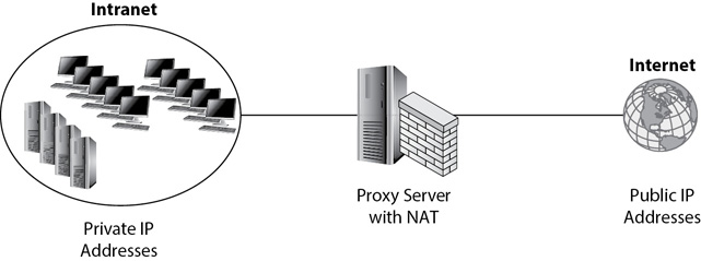
Figure 3-12 Using a proxy server with NAT
One of the benefits of NAT is that internal clients do not need public IP addresses to access the Internet. This provides a layer of protection for these clients because they aren’t directly accessible from other Internet clients. It also reduces costs for an organization because the organization needs to purchase public IP addresses only for the proxy server and not for every internal client.
Smaller networks often use NAT on a router instead of a proxy server. For example, wireless routers used in small wireless networks often include NAT. All internal clients use private IP addresses and access the Internet via the wireless router.
NAT is typically identified as either static or dynamic:
• Static Maps an unregistered private IP address to a registered public IP address on a one-to-one basis. Static NAT allows an internal client to communicate with devices on the Internet with the same IP address.
• Dynamic Uses multiple public IP addresses and maps private IP addresses to one of the public IP addresses based on a first-come, first-served basis.
Port Address Translation (PAT) is an extension of NAT that maps multiple private IP addresses to a single public IP address using different ports. As an example, imagine the proxy server in Figure 3-12 is using PAT instead of NAT and Sally uses her web browser to connect to mcgraw-hill.com from the private network. The PAT server changes the request using the PAT server’s public IP address as the source IP address, and it changes the source port to a unique source port number, such as 49,152. When the PAT server receives the response, it has a destination port of 49,152. The proxy server recognizes this port and modifies the packet using Sally’s original private IP address and port number, and forwards it to her computer.
EXAM TIP Static NAT uses a one-to-one mapping with a single IP address, but dynamic NAT uses a one-to-many mapping with multiple IP addresses. PAT is an extension of NAT that uses a many-to-many mapping using port numbers.
Comparing Trust Relationships
Networks utilize trust relationships to simplify access control. The three primary types of trust relationships are one-way, two-way, and transitive. Refer to Figure 3-13 when reviewing the following explanations:
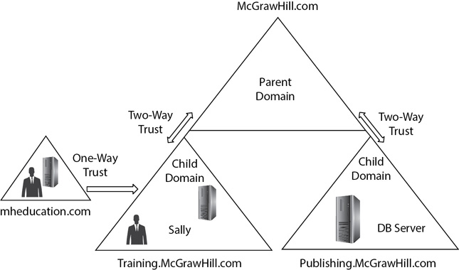
Figure 3-13 Trust relationships
• One-way trust A one-way trust allows subjects (such as users) in one domain to access resources in another domain. For example, Figure 3-13 shows a one-way trust relationship where mheducation.com trusts Training.McGrawHill.com. This would allow users in the Training.McGrawHill.com domain (such as Sally) to access resources in the mheducation.com domain. However, users in the mheducation.com domain would not be able to access resources in the Training.McGrawHill.com domain.
NOTE A one-way trust does not automatically grant permissions. In other words, everyone in the Training.McGrawHill.com domain would not automatically have access to all resources in the mheducation.com domain. However, the one-way trust makes it possible to grant users permissions to the resources.
• Two-way trust A two-way trust indicates that both domains trust each other. In Figure 3-13, there is a two-way trust between the parent domain (McGrawHill.com) and each child domain (Training and Publishing). You can also think of this as two one-way trusts.
• Transitive trust A transitive trust is an indirect trust relationship. In Figure 3-13, the Training domain and the Publishing domain do not have a direct trust relationship. However, because they both have a two-way trust relationship with the parent domain (McGrawHill.com), it creates a transitive trust relationship between both domains. This allows users in the Training domain to access resources in the Publishing domain, and it allows users in the Publishing domain to access resources in the Training domain. This doesn’t mean they automatically have full rights and permissions in the other domain. However, administrators can grant users rights and permissions when the transitive trust relationship exists.
Exploring Wireless Technologies
Wireless technologies are quite popular in both homes and organizations. With a wireless network (sometimes called a WiFi network), computers connect to each other and network devices by transmitting data over the airwaves. There are five primary IEEE 802.11 standards for wireless local area network currently supported by most access points or wireless routers. Table 3-3 outlines the base frequency and theoretical maximum speeds of each.
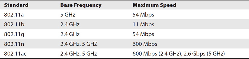
Table 3-3 802.11 Wireless Standards
NOTE The speed is the maximum speed in ideal conditions. However, many variables affect the actual speed. For example, as the distance increases between two wireless devices, the actual speed decreases. Obstructions such as walls and interference from EMI or RFI also reduce the actual speed.
Other standards have been defined and are being developed, but they are not widely supported as I write this chapter. As an example, 802.11af was approved in February 2014 and supports the use of unused television channels. 802.11ax is slated to be an upgrade to 802.11ac with a goal of providing four times the throughput of 802.11ac.
A wireless network includes a wireless access point (AP) or a wireless router. Wireless devices, such as laptops, tablets, and smartphones, connect to the network through the AP or the wireless router. An AP provides a bridge for wireless clients to a wired network. For example, Figure 3-14 shows an AP for an organization with one user connecting to the AP with a smartphone while another user is connecting with a laptop. Once connected, the wireless clients are able to access any resources in the network, just as other wired clients can.
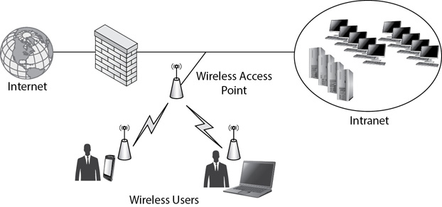
Figure 3-14 Wireless users connecting to a network via an AP
Wireless routers include additional capabilities beyond the AP. Technically, they are access points with routing capabilities, but they are widely marketed as wireless routers. They are used in small offices and home offices (SOHOs), along with many home networks. Some of the common capabilities found in a wireless router include
• AP Provides a bridge for wireless clients to the wired network.
• DHCP Provides both wired and wireless clients with TCP/IP configuration information, such as IP addresses, subnet masks, the address of a DNS server, and more.
• NAT Translates between private IP addresses used internally and public IP addresses used on the Internet. Wireless routers typically use PAT, which is an extension of NAT.
• Routing Provides basic routing between the internal network and the Internet. The wireless router is the default gateway for all internal clients.
• Basic firewall Provides basic firewall capabilities to filter traffic, but the capabilities can differ substantially from one brand to another.
Figure 3-15 shows an example of a wireless router within a network. This wireless router is providing many additional services for both wired and wireless clients. All clients access the Internet via this wireless router.

Figure 3-15 Wireless users connecting to a network via a wireless router
Wireless systems typically transmit in multiple directions (omnidirectional) at the same time. The area where wireless systems can receive the signal is the wireless footprint. Within an organization, walls or devices transmitting EMI or RFI reduce the overall footprint.
However, an attacker can extend the footprint of a wireless network by using a receiver with a directional antenna. For example, it’s possible to hook up something as simple as a can to a wireless antenna (creating a cantenna) and then point the can toward the wireless transmitter. Some tests have shown that an attacker can capture transmissions of wireless networks more than a mile away by using a cantenna.
Securing Data Transmissions
Because wireless technologies transmit data over the air using radio waves, it’s easy for an attacker to capture the data with a wireless receiver. This can be as simple as installing a wireless sniffer on a laptop that includes wireless capabilities. For example, Wireshark is a free sniffer application that includes the ability to capture wireless transmissions. An attacker can download and install it, and then sit in an organization’s parking lot and capture wireless transmissions.
TIP Wireshark can capture all transmissions as long as the NIC is in promiscuous mode. If it’s not in promiscuous mode, Wireshark only captures traffic addressed to or from the Wireshark client. The challenge with capturing wireless transmissions is that many wireless NICs do not support promiscuous mode. However, some USB-based adapters such as Riverbed AirPcap support promiscuous mode.
Secure wireless transmissions make it more difficult for an attacker to capture any usable information from these transmissions. The three primary security protocols are Wired Equivalent Privacy (WEP), Wi-Fi Protected Access (WPA), and Wi-Fi Protected Access 2 (WPA2).
WEP was the first security algorithm used for 802.11 wireless networks. The goal was to provide the same level of privacy on a wireless network as users could achieve on a wired network. It failed. WEP has several security issues and should not be used.
WPA was the interim replacement for WEP. The goal was to provide better security immediately for wireless devices using existing hardware. In other words, users running WEP could switch over to WPA without purchasing new wireless adapters, wireless access points, and/or wireless routers. Although WPA is much better than WEP, its designers never intended it to be a permanent replacement. WPA has known vulnerabilities and is susceptible to WPA cracking attacks allowing an attacker to discover the WPA preshared key (PSK), which is a password or passphrase of 8 to 63 characters.
WPA2 is the permanent replacement for WEP and WPA. The IEEE formally ratified it in 2004 as 802.11i. WPA2 requires different hardware than WEP and WPA2. However, the Wi-Fi Alliance requires that all new hardware support WPA2 and Counter Mode with Cipher Block Chaining Message Authentication Code Protocol (CCMP) in order to be Wi-Fi Certified. The Wi-Fi Alliance is a global nonprofit organization that has helped standardize wireless technologies.
WPA originally used only Temporal Key Integrity Protocol (TKIP). TKIP could use the same hardware as WEP, but provided significantly more security than WEP. Later implementations of WPA support Advanced Encryption Standard (AES), a much stronger encryption standard than TKIP.
WPA2 uses CCMP, which is based on AES and is much stronger than WPA using either TKIP or AES. WPA2 with CCMP is the recommended standard for security.
WPA-Personal and WPA2-Personal
WPA-Personal and WPA2-Personal use a preshared key (PSK). WPA/WPA2 then uses this PSK to create an encryption key, which wireless devices use to encrypt and decrypt wireless traffic. It’s worth stressing that the PSK isn’t the encryption key itself, but instead the PSK is used to create the key.
TIP This encryption key is used by either AES or TKIP for symmetric encryption depending on whether the system is using WPA2 or WPA. Chapter 14 explores symmetric encryption and AES in more depth.
Administrators enter the PSK into the AP or wireless router, and users then enter the same PSK into their wireless devices. For example, Figure 3-16 shows one of the setup pages for a Linksys wireless router. The PSK is IW!llBe$$CPCertified. You can also see that WPA2-Personal is selected, and on this router, WPA2-Personal uses AES-based CCMP.

Figure 3-16 Configuring security for a wireless router
WPA-Enterprise and WPA2-Enterprise
An organization can increase security with wireless networks by adding an 802.1x authentication server and using Enterprise mode. A Remote Authentication Dial-In User Service (RADIUS) is commonly implemented as the 802.1x authentication server. Both WPA and WPA2 support Enterprise mode.
EXAM TIP Enterprise mode requires an 802.1x authentication server and increases security by requiring clients to authenticate before granting them access.
When an 802.1x authentication server is added, the clients are required to authenticate (such as with a username and password) prior to being granted access to the network. Additionally, clients don’t need to enter a PSK. Instead, the system creates and assigns unique encryption keys after the clients log on. In contrast, Personal mode requires users to know and enter the PSK shared by all users.
An 802.1x authentication server will often be configured to check an authentication database on another server. For example, in a Microsoft domain, the 802.1x authentication server can check a user’s credentials via a domain controller hosting Active Directory Domain Services. Users log on using their domain credentials. If they don’t have an Active Directory account, they cannot log on and cannot access the wireless network.
Although the focus in this section is to use an 802.1x authentication server to authenticate wireless clients, an 802.1x authentication server can also be used to authenticate other clients. For example, it can be used to authenticate DHCP clients prior to providing TCP/IP configuration information.
EXAM TIP WEP should not be used because it has several security vulnerabilities. Additionally, WPA has known vulnerabilities and should not be used. WPA2 with CCMP is recommended over WPA2 with TKIP. If legacy hardware doesn’t support WPA2, WPA might be the only alternative to WEP. WPA-Personal and WPA2-Personal use a PSK. WPA-Enterprise and WPA2-Enterprise use an 802.1x authentication server, providing a higher level of security.
Wireless Device Administrator Password
Wireless devices such as APs and wireless routers commonly have a web-based administration program that you can access with a basic web browser. You can access this program using the IP address assigned to the router (often either 192.168.0.1 or 192.168.1.1). You enter the IP address as the URL in your browser. When you connect, the wireless router prompts you to provide the name of the administrator account and the administrator password.
You can check the manual (or the Internet) for the default name and password if the device uses defaults. A common default combination used in older APs and wireless routers is admin (for the administrator account) and admin (as the password), although there are many variations. Most newer devices force you to create the password for the device when you first set it up.
If the device has a default password, an important step in securing the wireless device is to change the password from the default. Ideally, you’ll change it to a strong password or passphrase. If you don’t, an attacker might see your wireless network, log in using the defaults, and modify your network. An attacker can actually lock you completely out of your network until you reset the wireless device to factory defaults.
TIP Wardriving is the practice of driving around with a wireless receiver (such as a laptop with a wireless NIC) and looking for wireless networks.
Wireless Service Set Identifier
The service set identifier (SSID) is the name of the wireless network. Many wireless devices have default SSIDs, but newer ones often require the user to enter the name of the SSID as part of the setup process. For example, some common SSIDs for older wireless routers were Linksys (for Linksys systems) and Netgear (for Netgear devices).
An SSID can be almost any name you want, although it can’t be longer than 32 characters. It’s a user-friendly name, but you don’t necessarily want to make it user friendly to attackers. For example, if your wireless network includes secret financial data, you probably don’t want to call it SecretFinancialData.
Figure 3-17 shows the configuration page for a Cisco wireless router with the SSID entered as SSCPWireless. You can also see that the Broadcast SSID setting is checked, enabling SSID broadcast. When the wireless device is set to enable wireless SSID broadcasting, it regularly broadcasts messages with the SSID name. This enables other wireless devices in range of the broadcast to easily identify the wired network, and if they have security configured to match the wireless router, the SSID broadcast allows these other devices to connect easily.
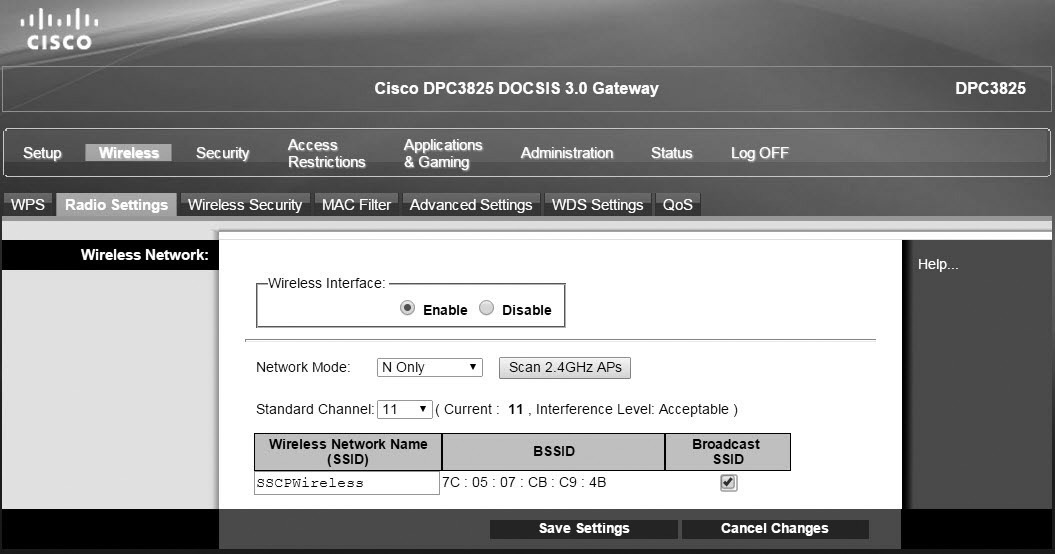
Figure 3-17 Configuring the SSID
TIP Figure 3-17 shows other settings. It’s possible to convert this to a wired router only by setting the Wireless Interface to Disable. The Network Mode is set to N Only using 2.4 GHz, so it only supports 802.11n devices on 2.4 GHz. It can also be configured to support 802.11b, 802.11g, and 802.11n devices in mixed mode. This page also allows you to select the wireless channel, which is useful to avoid interference on another channel.
An ongoing discussion related to the SSID is whether you should enable or disable SSID broadcasting. Many people originally recommended disabling SSID broadcasting to hide the network. However, this really doesn’t provide security. Even though this stops the normal SSID broadcasts used by other wireless devices, it doesn’t prevent the device from transmitting the SSID over the air. An attacker with a wireless sniffer can easily capture key packets and discover the SSID, even when SSID broadcasting is disabled.
MAC Address Filtering
Most wireless devices also provide the ability to filter connections based on MAC addresses. For example, Figure 3-18 shows a configuration page for a wireless router with a Wireless MAC Filter set to Enable. As configured, it will permit one computer with the MAC address of 1A:2B:3C:4D:5:6F access to the network. It will block access to all other computers.
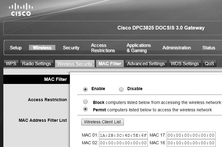
Figure 3-18 Enabling a MAC address filter
However, it’s quite simple to spoof the MAC address of a system. An attacker with a wireless sniffer can identify the MAC addresses that are connecting to a wireless network. Armed with this knowledge, the attacker can then use software to change the wireless MAC address of the attacker’s system and then connect.
In theory, MAC address filtering as a security precaution sounds good. In practice, it’s easily defeated. The best protection you can use is WPA2 with CCMP. If you have a choice and can configure an 802.1x authentication server, use WPA2-Enterprise instead of WPA2-Personal (WPA2-PSK).
Bluetooth
Bluetooth is a wireless technology used for small wireless networks commonly called personal area networks (PANs). As an example, smaller wireless devices such as smartphones along with an earpiece and microphone use Bluetooth. A user can wear a Bluetooth-enabled earpiece while keeping a Bluetooth phone in their pocket.
Devices must be paired with each other before they will communicate. Pairing is done by changing the devices to discovery mode so that they can easily locate each other and connect. Once they are paired, discovery mode should be disabled. If discovery mode is left enabled, an attacker can pair with the devices and take them over. It’s relatively easy for a user running Linux to exploit a Bluetooth device left in discovery mode.
The following are three well-known types of Bluetooth attacks:
• Bluesnarfing A hacker that is able to pair with a Bluetooth-enabled smartphone can access data on the device. The attacker can access information on the user’s phone such as e-mail, contact lists, calendars, and text messages. The attacker must be close to the phone (usually within 30 feet).
• Bluebugging In some instances, an attacker is able to access a smartphone and issue specific commands to it. This enables the attacker to make phone calls, enable call forwarding, send messages, read and write data, connect to the Internet, and turn on the speaker to eavesdrop on conversations.
• Bluejacking Compared to Bluesnarfing and Bluebugging, Bluejacking is relatively harmless. It allows users to send unsolicited messages to nearby Bluetooth devices, but it does not involve modifying a phone’s data.
NFC
Near field communication (NFC) is a technology available on many smartphones that allows users to make purchases with those smartphones. For example, if you have an NFC-enabled smartphone, you can make a purchase at a store by simply tapping your smartphone on the NFC reader or waving it close to the reader. Similarly, users can share information with each other by identifying the information to share and tapping the two devices together.
NFC uses similar technology as a proximity card, allowing devices to communicate with each other when they are in close proximity. The devices transmit and receive data only between short distances (identified as a near field). NFC encrypts this data, providing some protection. Additionally, it’s often possible to configure the device to require the user to enter a PIN or authenticate with a fingerprint before it transmits any data.
Of course, if you add your credit information to your NFC-enabled smartphone, it does make the risk of losing your phone that much greater, especially if additional security hasn’t been configured on the device. If someone steals your phone and can access it, they can wave and tap it during a massive shopping spree that will be billed on your credit card.
GSM
Global System for Mobile Communications (GSM) began as a European standard for 2G, or digital cellular, networks in 1982. As a comparison, 1G refers to the analog communications that came out in the 1980s, and 2G refers to the digital technologies that came out in the 1990s. Industries embraced the GSM standard and it has since grown into a large family of technologies used in mobile communications.
GSM is a standard used in 219 countries (including the United States). The GSM Association (GSMA) includes almost 800 mobile operators and 200 other companies that help standardize, deploy, and promote the GSM standard.
3G, LTE, and 4G
3G refers to the third generation of standards for wireless access used by mobile phones and mobile telecommunications. 3G provides higher transmission speeds for mobile communications, comparable to broadband speeds that wired users have. Speeds up to 3 Mbps are common. Users can surf the Web with a mobile phone and access other web-based services such as e-mail.
Improvements of 3G are sometimes dubbed 3.5G and 3.75G. They use High Speed Packet Access (HSPA), and in many cases, users can get 20 Mbps download times or better. However, not everyone can achieve these high rates of downloads. Worse, when large numbers of cellular users are operating in the same area, all users have reduced speeds because they’re competing for the same bandwidth.
Telecommunication companies often market Long-Term Evolution (LTE) as 4G, but it doesn’t always match the speed of 4G or meet the technical specifications. 4G (the fourth generation of mobile telecommunications) includes speeds as high as 100 Mbps for highly mobile users in trains and cars, and 1 Gbps for individuals walking or staying still.
New generations of telecommunications appear about every ten years. Fully compliant 4G systems were standardized in 2012. With that in mind, 5G systems are likely to appear sometime after 2020.
WiMAX
Worldwide Interoperability for Microwave Access (WiMAX) is a standard based on IEEE 802.16. IEEE 802.16 is officially known as Wireless MAN, but is commercially known as WiMAX. WiMAX provides broadband wireless coverage to large areas or metropolitan area networks (MANs).
For example, a WiMAX fixed station can provide wireless access for up to 30 miles. In comparison, wireless local networks using 802.11 are limited to about 300 feet. Many providers have created WiMAX networks around the world, and users can rent access to the networks. WiMAX provides speeds up to 1 Gbps for wireless connections.
Radio Frequency Identification
Radio frequency identification (RFID) is used for identification, tracking, asset management, and inventory control. Products are “tagged” with an RFID tag, which is a small electronic device that marks the product. RFID readers can then read the tag to get information about the product.
RFID tags can be either active (with a battery) or passive (without a battery). Active RFID tags are constantly transmitting. A passive RFID tag works similarly to how proximity cards work for authentication. An RFID reader can excite the electronics on the RFID tag and cause the tag to transmit its information.
TIP Chapter 2 describes proximity cards in more depth within the “Something You Have” section.
Protecting Mobile Devices
The primary vulnerabilities with mobile devices occur if they are lost. If someone finds or steals a mobile device, that person may be able to get some valuable information. With this in mind, users can do several things to protect their devices. These include the following:
• Password protect devices Most devices support password protection. Users must enter a password or personal identification number (PIN) to unlock the device to use it. If a thief gets the device, this password makes it more difficult for the thief to access the data.
• Encrypt data Many devices support data encryption, and some even support full device encryption. If a thief does get an encrypted smartphone, the encryption provides confidentiality by restricting the thief’s access to the data. This encryption is often enabled by default when a passcode (such as a PIN) is enabled.
• Remote wipe Some devices support remote wipe. This allows the owner to send a command to a lost device to delete all the data on the device. The command will delete cached data, such as cached passwords, along with other data such as information in the user’s contact list. For mobile devices that do not have a built-in remote wipe capability, users can install apps to perform the same function.
• Enable GPS Many devices support global positioning system (GPS) location services. If the device is lost, the user can use the GPS service to determine its location.
EXAM TIP Mobile devices are easily lost. Because they can often contain valuable data, it’s important to know the different methods available to protect data. Password protection and data encryption are valuable if done before the device is lost. Remote wipe and GPS are valuable after the device is lost.
While this section identified some specific security controls that users can implement to protect their devices, it’s also possible for an organization to configure these settings remotely. Chapter 9 covers mobile device management (MDM) in more depth.
Chapter Review
The OSI Model is a framework for connecting multiple computers to each other. The ISO developed it and it has seven layers. The layers, listed from layer 1 to layer 7, are Physical, Data Link, Network, Transport, Session, Presentation, and Application. The TCP/IP Model (also called the TCP Model and the DoD Model) is similar to the OSI Model, but it has fewer layers. RFCs 1122 and 1123 identify four layers of the OSI Model, but some references identify five layers.
Two important protocols operate on the Transport layer (layer 4). They are TCP and UDP. TCP is connection-oriented and establishes sessions with a three-way handshake. UDP is connectionless and doesn’t use a three-way handshake to establish a session. Instead, UDP uses its best effort to send the data. Other protocols can work with either TCP or UDP, depending on the protocol’s needs. For example, FTP uses TCP for guaranteed delivery, while TFTP uses UDP.
Network configurations include bus, star, tree, token ring, and mesh. In a bus configuration, all devices share a common bus cable connection that has terminators at both ends. A bus is inexpensive to install but very difficult to troubleshoot, increasing the total cost of ownership. A star configuration is much more common and uses a central device such as a switch. All devices connect to each other via the central device in a star. A tree is a combination of bus and star topologies. A token ring configuration uses a logical token, and devices in the ring can transmit only when they have the token. Traditional token ring configurations are slower and don’t scale well. FDDI uses a token ring concept but adds a second ring for redundancy and has significantly higher speeds because it uses fiber-optic cables. Mesh networks have multiple redundant connections, connecting each device with all other devices, and they provide the highest availability.
Network relationship types include peer-to-peer and client-server. Smaller networks use a peer-to-peer configuration and have decentralized authentication. Larger networks typically use a client-server configuration with centralized authentication. In a Microsoft environment, user accounts are maintained and managed on domain controllers.
TCP/IP includes a full suite of protocols used by computers on the Internet and on many internal networks. The SSCP exam doesn’t expect you to be an expert on all the protocols within TCP/IP, but you should be familiar with many of them.
DHCP provides IP addresses and other TCP/IP configuration information to hosts. ARP resolves IPv4 addresses to MAC addresses and must be running to transfer data on a network. RARP is similar to DHCP in that it provides IP addresses to clients with MAC addresses (also known as physical or hardware addresses). BootP provides diskless clients with an operating system. NDP is similar to ARP but resolves IPv6 addresses to EUI-64 addresses.
DNS uses a hierarchical naming system with a distributed database to resolve host names to IP addresses. DNSSEC protects against DNS poisoning attacks using Resource Record Signatures (RRSIGs), which are similar to digital signatures. The digital signature provides authentication of the response, validating the integrity of the DNS response.
ICMP is used for diagnostics. While it is useful when it is running, it is often disabled or blocked at firewalls to thwart attacks that use ICMP. IPv4 uses IGMP for multicasting, while IPv6 uses ICMPv6 for multicasting. SNMP is used to manage network devices. Agents receive data on UDP port 161 and send traps and other data over UDP port 162.
FTP is efficient for sending large files, while TFTP is good for sending small files such as configuration files for network devices. FTP uses TCP ports 20 and 21, and supports authentication. TFTP uses UDP port 69 and does not include authentication. Both FTP and TFTP send data across a network in cleartext.
Sending data over a network in cleartext is a security risk because an attacker with a sniffer can capture these transmissions and read the data. Several protocols, such as Telnet and rlogin, send credentials over a network in cleartext. SSH is a more secure alternative as it encrypts the transmissions using a combination of symmetric and asymmetric encryption for confidentiality. SSH uses hashing for integrity, and can use an authenticated tunnel for mutual authentication. SSH can also encrypt other protocols such as FTP (as SFTP) and Secure Copy. SSH uses TCP port 22.
HTTP is the common protocol used to transfer web pages over the Internet. HTTPS encrypts e-commerce transactions with SSL or TLS. TLS is the designated replacement for SSL. HTTP uses TCP port 80 and HTTPS uses TCP port 443.
Routers use routing protocols such as RIPv2 and OSPF to share information with each other. RIPv2 is good for smaller networks, while OSPF works better in larger networks. Both protocols operate on the Network layer.
E-mail protocols include SMTP, POP3, and IMAP4. Clients send e-mail with SMTP and receive e-mail with POP3. IMAP4 allows clients to access and manipulate e-mail on a server, including organizing e-mail within folders. SMTP uses TCP port 25, POP3 uses TCP port 110, and IMAP4 uses TCP port 143.
VPNs use tunneling protocols to protect data. PPTP and L2TP are two tunneling protocols, and both operate on the Data Link layer. PPTP provides encryption, while L2TP depends on IPsec for encryption. IPsec uses AH for authentication and integrity. IPsec ESP includes the functionality of AH and provides confidentiality by encrypting the data. AH uses protocol number 51, and ESP uses protocol number 50. TLS can also be used as a VPN tunneling protocol.
Both TCP and UDP can use any of 65,536 ports (numbered from 0 to 65,535). Ports 0 to 1023 are well-known ports, and IANA maps them to specific protocols. For example, SSH uses port 22, HTTP uses port 80, and SMTP uses port 25. You should be able to identify the port used by many common protocols, in addition to the protocol numbers used by other protocols.
Different network architectures provide different levels of trust. For example, an intranet is internal within an organization and provides a high level of trust. The Internet is external and has the least level of trust. A DMZ hosts Internet-facing servers that are accessible by anyone on the Internet, and an extranet hosts Internet-facing servers that are accessible only by trusted entities such as business partners. Internal clients use private IP addresses, and Internet hosts have public IP addresses. NAT translates IP addresses from public to private and from private back to public.
Wireless networks (sometimes called WiFi networks) allow clients to connect using radio-wave transmissions. These radio-wave transmissions are the easiest to capture and intercept (compared to transmissions on wired networks), but some basic security steps can increase the security of a wireless network. WEP is older and should not be used. WPA was an interim replacement for WEP and was compatible with existing hardware. WPA2 is the permanent replacement and is formally defined by 802.11i. WPA originally used TKIP, but many WPA systems also support AES. WPA2 uses AES-based CCMP. Both WPA and WPA2 can use Personal mode (with a preshared key) or Enterprise mode. Enterprise mode requires an 802.1x authentication server.
Smaller wireless devices use technologies such as Bluetooth, NFC, GSM, 3G, LTE, 4G, and WiMAX. Several methods protect these devices if they are lost. Methods include password-protecting the devices, encrypting data on them, using remote wipe to delete data on lost devices, and enabling GPS to locate lost devices.
Questions
1. Which layer of the OSI Model defines cable standards?
A. Physical layer
B. Data Link layer
C. Network layer
D. Transport layer
2. Which layer of the OSI Model packages data as a frame?
A. Physical layer
B. Data Link layer
C. Network layer
D. Transport layer
3. Which layer of the OSI Model provides reliable end-to-end communication services?
A. Physical layer
B. Transport layer
C. Data Link layer
D. Host layer
4. Which layer of the OSI Model includes TCP and UDP?
A. Transport layer
B. Network layer
C. Data Link layer
D. Application layer
5. Which of the following protocols is connection-oriented?
A. IP
B. RIP
C. TCP
D. UDP
6. User accounts are located on a central authentication server. What type of network relationship does this represent?
A. Peer-to-peer
B. Client-server
C. Star
D. Tree
7. What protocol would a system use to determine a system’s physical address?
A. ARP
B. RARP
C. BootP
D. DNS
8. Your organization plans to place a server in the DMZ to provide name resolution services. However, management wants to ensure that data it sends maintains integrity. Which of the following will BEST meet these goals?
A. DNS
B. TLS
C. DHCP
D. DNSSEC
9. Which of the following is the recommended protocol to secure HTTPS sessions?
A. SSL
B. TLS
C. SSH
D. IPsec
10. Which of these ports does DNS use?
A. TCP 22
B. TCP 25
C. UDP 53
D. UDP 69
11. Which of the following protocols is commonly used with diagnostic utilities?
A. TFTP
B. RARP
C. IGMP
D. ICMP
12. Which of the following accurately identifies a difference between FTP and TFTP?
A. FTP uses UDP, and TFTP uses TCP.
B. FTP supports authentication, but TFTP does not support authentication.
C. TFTP sends data across a network in cleartext, but FTP encrypts data.
D. TFTP is primarily used to transfer large files, and FTP is used to transfer configuration information to and from network devices.
13. Which of the following protocols is the most secure method to remotely administer a server?
A. Telnet
B. rlogin
C. rexec
D. SSH
14. What port does POP3 use?
A. 25
B. 110
C. 143
D. 443
15. You are purchasing a product from a website. Which of the following protocols will your system most likely use to provide confidentiality for this transaction?
A. TLS
B. SSH
C. IPsec
D. HTTP
16. Which of the following statements is correct related to IPsec?
A. IPsec provides confidentiality by encrypting data with AH.
B. IPsec provides confidentiality by encrypting data on the Network layer.
C. IPsec AH uses protocol number 50.
D. IPsec ESP uses protocol number 51.
17. You need to allow IPsec AH through your firewall. Which of the following should you configure to allow this traffic through the firewall?
A. Port 50
B. Port 51
C. Protocol number 50
D. Protocol number 51
18. Where is a DMZ located?
A. Behind the intranet firewall
B. In front of the first intranet-facing firewall
C. In front of the first Internet-facing firewall
D. Behind the first Internet-facing firewall
19. Which of the following is the recommended security mechanism to use with wireless networks?
A. 802.11a
B. 802.11g
C. 802.11i
D. 802.11n
20. You have created a wireless network for guests and several guests have connected to the network in the past. Today, new guests are unable to see the wireless network. However, guests that connected to it previously are using it without any trouble. What is the MOST likely problem?
A. The PSK has been changed.
B. The AP is now using WPA2-Enterprise.
C. SSID broadcasting has been disabled.
D. MAC address filtering has been enabled.
Answers
1. A. Cable standards are defined at the Physical layer, layer 1. They are not defined at the Data Link layer (layer 2), the Network layer (layer 3), or the Transport layer (layer 4).
2. B. The Data Link layer packages data as a frame. The Physical layer packages data as bits. The Network layer packages data as a packet. The Transport layer packages data as a segment.
3. B. The Transport layer provides reliable end-to-end communication services. Neither the Physical layer nor the Data Link layer provides this service. The Host layer is on the TCP/IP Model, not the OSI Model.
4. A. The Transport layer includes the TCP and UDP protocols. These protocols are not implemented on the Network layer, the Data Link layer, or the Application layer.
5. C. TCP is connection oriented. IP uses TCP to provide a connection-oriented session but is not connection-oriented itself. RIP is a routing protocol and is not connection-oriented. UDP is connectionless. Instead of establishing a session, it makes a best effort to deliver data.
6. B. In a client-server network relationship, users log on to a central authentication server, such as a domain controller. A peer-to-peer network relationship has decentralized authentication. Star and tree refer to network topologies, not network relationships.
7. A. Systems use the Address Resolution Protocol (ARP) to identify the assigned physical (or MAC) address matching an assigned IP address. Reverse ARP (RARP) allows a system with a MAC address to get an IP address. The Bootstrap Protocol (BootP) allows a diskless system to get an IP address and then download the image of an operating system. Domain Name System (DNS) resolves host names to IP addresses but not physical addresses.
8. D. Domain Name System Security Extensions (DNSSEC) adds security to DNS systems and best meets these goals. DNS responses are signed with a Resource Record Signature (RRSIG) to provide authentication of the response and prove it hasn’t lost integrity. While a server that provides name resolution services is a DNS server, a DNS server without DNSSEC will not meet the stated goals. While DNSSEC can use Transport Layer Security (TLS), TLS by itself provides encryption for confidentiality, not authentication for integrity. Dynamic Host Configuration Protocol (DHCP) assigns TCP/IP configuration information for DHCP clients and is unrelated to this question.
9. B. Transport Layer Security (TLS) encrypts Hypertext Transfer Protocol Secure (HTTPS) sessions. Secure Sockets Layer (SSL) has known vulnerabilities and should not be used. Secure Shell (SSH) is used to connect to remote servers, but not to encrypt HTTPS. Internet Protocol security (IPsec) is used to encrypt VPN tunnels, but not for HTTPS.
10. C. Domain Name System (DNS) uses UDP port 53 when clients query the DNS server and TCP port 53 when DNS servers transfer data between each other. Secure Shell (SSH) uses TCP port 22. Simple Mail Transfer Protocol (SMTP) uses TCP port 25. Trivial FTP (TFTP) uses UDP port 69.
11. D. Many diagnostic utilities such as ping, pathping, and tracert use Internet Control Message Protocol (ICMP). Administrators commonly use Trivial FTP (TFTP) to transfer configuration files to and from network devices. Reverse ARP (RARP) allows a system with a MAC address to get an IP address. The Internet Group Message Protocol (IGMP) is used for IPv4 multicasting.
12. B. File Transfer Protocol (FTP) supports authentication, but Trivial FTP (TFTP) does not support authentication. FTP uses TCP ports 20 and 21, while TFTP uses UDP port 69. Both FTP and TFTP send data across a network in cleartext, but it is possible to encrypt FTP with Secure Shell (as SFTP). TFTP is commonly used to transfer configuration files to and from network devices, and FTP is primarily used to transfer large files.
13. D. Secure Shell (SSH) encrypts data sent over a network and is the most secure method for remotely accessing systems of the given choices. Telnet, rlogin (which is remote login), and rexec (remote execute) all send data across a network in cleartext.
14. B. Post Office Protocol version 3 (POP3) uses TCP port 110. Simple Mail Transfer Protocol (SMTP) uses TCP port 25. Internet Message Access Protocol version 4 (IMAP4) uses TCP port 143. Hypertext Transfer Protocol Secure (HTTPS) uses TCP port 443.
15. A. E-commerce transactions use Hypertext Transfer Protocol Secure (HTTPS) for confidentiality, and Transport Layer Security (TLS) is used to encrypt HTTPS. While Secure Shell (SSH) and Internet Protocol security (IPsec) both provide confidentiality with encryption, HTTPS doesn’t use SSH or IPsec. HTTP sends data in cleartext, so it doesn’t provide confidentiality.
16. B. Internet Protocol security (IPsec) provides confidentiality by encrypting data on the Network layer. Encapsulating Security Payload (ESP) provides confidentiality by encrypting data, but Authentication Header (AH) only provides authentication and integrity. AH uses protocol number 51, and ESP uses protocol number 50.
17. D. You should enable protocol number 51 because it is the protocol number for Internet Protocol security (IPsec) Authentication Header. The protocol number for IPsec Encapsulating Security Protocol (ESP) is 50. IPsec AH and ESP are identified by protocol numbers, not port numbers.
18. D. A demilitarized zone (DMZ), or perimeter network, is located behind the first Internet-facing firewall. It is not on the private network (behind the intranet firewall) or directly on the Internet (in front of the intranet or Internet-facing firewall).
19. C. The 802.11i standard documents Wi-Fi Protected Access 2 (WPA2), the recommended security mechanism for wireless networks. It uses AES-based CCMP for very strong security. The other standards focus on the base frequency and speed of wireless networks, not security.
20. C. The most likely problem is that service set identifier (SSID) broadcasting has been disabled, primarily because new users are unable to see the wireless network. Clients that previously connected could have configured their systems to connect automatically. If the preshared key (PSK) was changed or the AP was changed to use WPA2-Enterprise, no one would be able to connect. It would be extremely difficult to enable media access control (MAC) filtering for only guests that previously connected, so this is highly unlikely.