
HOUR 18
Putting the Pieces Together
What You’ll Learn in This Hour:
• The Internet layered model
• Key interfaces and protocols explained in Hours 1 through 17
• How interfaces and protocols fit into the model
• How interfaces and protocols correspond with each other
We’ve covered a lot of material in only 17 hours. Perhaps you’re thinking, “It’s taken me longer than 17 hours to read the 17 chapters!” If you’ve only read the material, you can succeed in making it to this page in about 17 hours. However, if you’ve studied the material, I suspect (and hope) the journey took a bit longer.
Nonetheless, because of the scope of the material covered in this book, this is a good time to summarize and review the key network components we’ve studied thus far. We also examine how these components correspond to each other. First, we review the functions of the layers of the Internet layered model that were introduced in Hour 3, “Getting Data from Here to There: How Networking Works.” Next, we identify the layers in which the network components reside. We also show the layers in which the Internet protocols reside. Finally, we review Ethernet and Internet names and addresses and explain how these identifiers fit into packets and frames. Thus armed, we can tackle the remaining hours with more confidence.
Review of Internet Layered Model
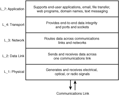
Figure 18.1 provides a general schema of the Internet layered model. We learned that the conventional OSI model contains seven layers. In contrast, the Internet model contains five layers, with Layers 5 and 6 folded into other layers, usually Layer 7. The layers perform these services:
• Layer 7 (application) contains the applications most familiar to users, such as email, text messaging, and file transfer. Most of the software used by network servers resides in this layer.
• Layer 4 (transport) is concerned with ensuring user data arrives safely at its destination. If a packet fails to reach the end user, the sending Layer 4 resends the packet. This layer is also responsible (in cooperation with the operating system, or OS) for ports and sockets.
• Layer 3 (network) provides network addressing, (maybe) route discovery, and routing services.
• Layer 2 (data link) defines a set of rules for transporting traffic on one communications link from one node to another node.
• Layer 1 (physical) is concerned with physical images, such as electrical, electromagnetic, and optical signals; the network interface cards (NICs); the wire; and cable. The modem is an example of a Layer 1 device.
FIGURE 18.1 Functions of Internet layers
Key Network Components’ Position in the Layers
In Hours 1 through 17, we learned about key components (principally software and protocols) used to operate a communications network. Figure 18.2 shows the placement of these components in the Internet layered model. We won’t rehash each of them, but we’ll offer amplifying comments to add to previous information. By the way, if some of these names don’t ring a bell, consult the index at the back of the book to review discussions about them.
FIGURE 18.2 Position of components in the layers

Just because a network component is shown to reside in one layer doesn’t mean it can operate correctly with only that layer. All network components at a higher layer must use one or more components at the layer(s) below to function properly—for that matter, to function at all. For example, IP can’t operate at Layer 3 if Layers 1 and 2 aren’t in place.
Most of the network components and their associated standards published by the Internet Engineering Task Force (IETF), Institute of Electronic and Electrical Engineers (IEEE), International Telecommunication Union (ITU), and other groups operate in one layer. Exceptions are Ethernet, whose IEEE standards define L_1 and L_2 procedures, and the various wireless technologies (Cellular, Wi-Fi, and Bluetooth) that reside in two or more of the layers.
With rare exceptions, Internet Protocol (IP) is the L_3 protocol that the applications and protocols in Layers 4 and 7 use. Internetwork Packet Exchange (IPX) is a counterpart to IP but is sinking into the sunset. Some forms of text messaging and other wireless applications haven’t yet migrated to IP, but they will.
The same holds true for the use of Transmission Control Protocol (TCP) or User Datagram Protocol (UDP) at Layer 4. Recall from Hour 14, “Connecting to the Internet: Initial Operations,” that TCP is used for traffic that requires end-to-end acknowledgments and overall data integrity. UDP is used for applications such as voice and video that don’t need, and can’t tolerate, the overhead of TCP.
We dealt briefly with L2TP in Hour 8, “Remote Networking.” It’s an enhancing protocol to PPP that uses IP to get its traffic to other nodes. It doesn’t use TCP or UDP; thus, it’s placed in L_4 of the model.
Several of the components in this model don’t concern themselves with the sending and receiving of traffic between network nodes. As examples, Classless Inter-Domain Routing (CIDR) and Network Address Translation (NAT) don’t unto themselves generate packets. I’ve placed them alongside IP in Layer 3 because they deal with IP address mapping, subnetting, and translation.
The operations of OSs and Network Operating Systems (NOSs) reside in Layer 7. These critical software packages are the heart and soul of computers, servers, and routers. They generate and receive a lot of traffic between network nodes and, of course, they initiate a lot of processing at the nodes themselves. Thus, they use the lower layers for these communications.
![]()
Placing an OS or an NOS in Layer 7 shouldn’t be construed to mean that this software depends on the lower layers. It’s quite the opposite, because Oss and NOSs control the operations of all these layers.
Many of the TCP and UDP port numbers have been reserved by the OS and NOS vendors. As examples, Microsoft’s Windows Internet Naming Service (WINS) package is identified with Internet port number 1512; the Windows File System is identified with number 5009.
In the past, OS and NOS messages were transported between nodes with vendor-specific protocols, such as NetWare’s IPX, Apple’s L_3 AppleTalk, and IBM’s L_3 Systems Network Architecture (SNA). With a few minor exceptions, vendors have migrated to the Internet protocols at Layers 3 and 4, and the IEEE, ITU-T, and IETF protocols at Layers 1 and 2. As cautioned in previous discussions, beware of the vendor who offers you proprietary network protocols. These vendors are becoming increasingly rare and are destined to become extinct.
Names, Addresses, and Sockets: The Cogs of Communications
In several of the past hours, we emphasized the value of the Internet’s standardization of names and addresses and software identifiers. Without these conventions, it’s fair to state that you and I would not be able to surf the Web or even send an email to each other.
We won’t rehash these services, but if they still seem a bit vague to you, look at these hours for information on the following names, addresses, and sockets:
Mac addresses: Hour 3
EtherType: Hour 3
IP addresses: Hour 3
IP Protocol Number:Hour 14
Ports and sockets: Hour 14
Domain Names: Hour 15
Relationships of Names, Addresses, and Sockets
Again, let’s tie together more pieces of the network puzzle. Figure 18.3 is used in conjunction with Figure 3.2 in Hour 3 and Figure 14.2 in Hour 14. Assume that data is forwarded out of Layer 7 from the sender to the receiver (Figure 3.2). At Layer 4, TCP or UDP creates a header containing the destination and receiving port numbers. The receiving Layer 7 software is Microsoft’s WINS, so the destination port number must be 1512. The sending port number is taken from a pool of numbers.
FIGURE 18.3 The Ethernet frame and layer process IDs
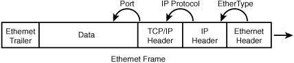
Next, the data is passed to IP at L_3. Here, IP (in conjunction with the OS) adds the source and destination IP addresses and places in its Protocol ID field a 6 for TCP, or 17 for UDP. Then, the data is passed to Ethernet at L_2, which adds the source and destination MAC addresses and fills in the value 0800 in the EtherType field to identify the IP packet.
At the receiver, the process is reversed, as seen in Figure 3.2. The MAC and IP addresses are used to route the data to the correct node on the network. The EtherType, IP Protocol ID, and destination port number are used to pass the data to the correct process in L_3, L_4, and L_7, respectively.
Common Locations of Components at Network Interfaces
In Hour 6, “Extending LANs with Wide Area Networks (WANs),” we introduced the three interfaces of a computer network. Recall that these interfaces represent the physical communications links between computers, servers, and routers. They aren’t operations within a machine. They represent the “pedal to the metal” traffic that flows between nodes. In Hour 6, Table 6.1, “Prominent WAN Interfaces,” explained the interfaces and set the groundwork for more explanations in Hour 7, “Mobile Wireless Networking.” Look at Table 6.1 in Hour 6. Granted, its contents are not a simple set of rows and columns, but I trust the table will make sense to you.
Summary
This hour has reviewed several key concepts discussed in previous hours, including the Internet layered model and the positions of major processes and protocols in the layers. In addition to this review, we’ve learned how the layers, protocols, and interfaces interwork with each other.
Q&A
Q. Your system is to execute a file transfer to another computer on the same local area network (LAN). Which protocols are likely to be executed for this operation?
L_7: _________
L_4: _________
L_3: _________
L_2: _________
L_1: _________
A. L_7: FTP
L_4: TCP
L_3: IP
L_2: Ethernet
L_1: Ethernet
Q. Your system is to execute an email transfer to another computer across your DSL. Which protocols are likely to be executed for this operation?
L_7: _________
L_4: _________
L_3: _________
L_2: _________
L_1: _________
A. L_7: POP3
L_4: TCP
L_3: IP
L_2: ATM
L_1: DSL
Q. Your system is to execute an email transfer to another computer across your cable modem. Which protocols are likely to be executed for this operation?
L_7: _________
L_4: _________
L_3: _________
L_2: _________
L_1: _________
A. L_7: POP3
L_4: TCP
L_3: IP
L_2: ATM
L_1: Cable modem digital signal
Q. You aren’t interested in end-to-end data integrity for these two operations. What changes are made to the protocol stack?
A. UDP is executed instead of TCP.