
HOUR 6
Extending LANs with Wide Area Networks (WANs)
What You’ll Learn in This Hour:
• The definition of a wide area network (WAN)
• Components of a WAN
• Key network interfaces
• Using carrier providers for the local interface: telephone (T-carrier systems and digital subscriber line, or DSL), cable, and satellite services
• Broadband WAN carrier systems
• How the Internet can help you assemble your WAN
Networks are often distributed over a wide geographical area, which may encompass too great a distance to tie them together with local area network (LAN) hardware and software. If LANs situated in remote locations need to be connected, they are interworked with a WAN. Of course, this concept assumes the WAN components are selected, assembled, and integrated properly with the LAN components, which we will begin to do in this hour.
What Is a WAN?
In previous hours, we introduced WANs and the general reasons for their existence. We now move to the details. First, most LANs’ media, such as copper wire or optical fiber, are installed, owned, and operated by individuals (such as you and me) or enterprises (such as banks and grocery stores). This Open Systems Interconnection (OSI) physical layer is located in our home or a company’s office. It might be situated among rooms in our home, or in between an enterprise’s office buildings—a campus, for example.
However, when connecting a LAN located in one part of the country to a LAN in another locale, we (and most companies) are not allowed to pull copper wire across the country. Even if we obtained government licenses to do so, it would be far too expensive an undertaking. Indeed, the proposition is absurd. If everyone “pulled cable,” millions of communications links would be laid to connect millions of LANs. Thus, like the public telephone networks, which support the connection of private telephone networks (private branch exchanges [PBXs], for example), public data networks—spread over a wide area—support the connection of private LANs and individual computers. One such public data network is the Internet, the mother of all wide area computer networks.
At this juncture, we need to emphasize the following about the public telephone networks and the public data networks. They
• Are now capable of transporting any image (voice, video, data, photos, and graphics)
• Have migrated to packet-switching technologies to carry this traffic
• Are blurring their former distinctions of being a “telephone” network or a “data” network
• Have altered their roles; an Internet service provider (ISP) might be a telephone company, such as Verizon, or a nontelephone company, such as AOL
To understand this situation, consider the conventional telephone network of some 40 years ago. AT&T and the Bell System were America’s common carriers. They built the fantastic network that carried our voice and video traffic. Their systems were not designed for data, but with the invention of one of the most important machines in history, the modem, data could be placed onto telephone lines. (The modem is examined in Hour 8, “Remote Networking.”)
The early Internet was formed by using the telephone network and adding modems and packet switches for the transport of data. As these telephone carriers evolved and as the Internet came into existence, their facilities began to look the same. As well, their roles began to merge. Nowadays, a “telephone” company, such as Verizon, does not restrict itself to telephone calls. It’s both an ISP and a conventional network provider. This situation is the reason for my comment about the “blurring” of roles between the telephone systems, the data networks, and the ISPs.
Notwithstanding this migration, WANs require someone to build and install expensive communications facilities. AT&T, the reconstituted telephone regional companies, and other enterprises are in this business. They lease their wide area communications links to anyone who will pay for the rentals, such as AOL. In turn, AOL might choose to add value to the links by installing Cisco routers and Hewlett-Packard servers to create a private internet. AOL will then enter into agreements called peering agreements with other companies to connect their facilities into the public Internet. For example, AOL might agree to interwork with MSN by allowing their respective customers’ traffic to pass across the WAN communications lines they have leased from, say, AT&T.
The result is the availability of both public and private WANs to connect our LANs or our plain old dial-up modems. One result is also the extraordinary Internet, a collage of millions of computers, thousands of ISPs, and hundreds of WAN companies. The Internet is an amazing phenomenon. Even more amazing, it works.
Here are three examples of WANs:
• The automated teller machines (ATM) machines scattered around a city and connected to a bank’s central processing facility. For control purposes, the bank leases lines from carriers and adds its own security and applications software.
• An international company with installations of groupware (shared collaborative software) at its remote locations around the world. To ensure the email and groupware messages operate reliably, the company uses leased lines instead of the Internet as a backbone. Therefore, this WAN is considered a private network.
• An international company with installations of groupware at its remote locations around the world. It chooses to use the Internet for its WAN backbone. Therefore, this WAN is called a virtual private network (VPN): It appears to be a private network, but it isn’t because it’s using the pubic Internet.
Components of a WAN
The main task of a wide area computer network is to transfer user traffic as quickly and securely as possible. The network is unaware of the contents of the traffic because it does not interact directly with the users and user applications software. Thus, it is not concerned with user-friendly graphical user interfaces (GUIs), mail servers, or file servers. These services are provided only when the traffic arrives at the node (say, a server) where the destination application is directly connected.
The notion of removing the WAN from direct communication with the user is of great importance, because it frees the network from repetitively executing millions of lines of software code. To see why, please refer to Figure 6.1. User packets are sent directly from a computer via a dial-up connection, a LAN, or a broadband link to a machine shown here as a LAN/WAN gateway. In practice, this device is likely a conventional router located at our home, our office, or the site of our ISP. Wherever it is placed, it is called a gateway because it does indeed provide a “gateway” from the local area to a wide area (and vice versa at the other end of the path).
FIGURE 6.1 Traversing a WAN
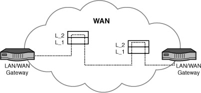
The dashed lines inside the WAN signify the packets’ journey through the network. The diagrams inside the WAN labeled “L_1” and “L_2” signify the lower two layers of the OSI model that operate in the machines at the WAN nodes. As you see, only the lower two layers of the model are invoked to process user packets. With minor exceptions, the upper layers aren’t executed inside the WAN for end user traffic.
Again, this design is quite significant because it keeps WANs “lean and mean.” They’re fast because (a) the equipment and software is optimized for speed and not user interactions; (b) the hardware nodes are connected with very high-speed links—orders of magnitude faster than the links you have in your home or office. The result is low delay and high throughput.
Yes, but what happens to all the wonderful services we obtain from computer networks? Where did our email windows go? Our bank account screens? Where are the text message templates? How does the WAN play our videos and our music? The answers to all these questions are the same: The data inside the packets might contain all this information, but the WAN does not process any of it. Its job is to ferry this data reliably and quickly to the end computer, the final mail server, the destination file manager, the receiving text messenger, and so on. At the final destination, the upper layers are finally invoked at servers and clients to provide us these services.
Thus, our email or text messages are transported transparently through the WAN only to be used at the final destination. Certainly, a WAN executes upper layer software for its own internal operations, such as network management, but it doesn’t execute this code for user traffic.
An elegantly simple solution to an immensely challenging problem: transporting millions of packets through these WANs in a few milliseconds. Given the amount of data involved, the magnitude of the user base, and the requirement for very fast response times and very low delays, these operations could not be performed satisfactorily if the network nodes executed the upper layers of the model. Fortunately, the WANs have no need to examine the upper-layer headers and data.
True, but how do the WAN nodes in Figure 6.1 know how to route the traffic? After all, in Hour 3, “Getting Data from Here to There: How Networking Works,” we learned that the IP addresses in the IP packet (datagram) are processed at Layer 3. We also learned the Layer 2 Ethernet addresses in the Ethernet frame are stripped away before reaching a WAN because they have only local significance. Is the WAN clairvoyant and somehow able to infer the destination address from the surrounding Ethernet ether? No. Let’s place some more pieces into our puzzle by examining the major components in the WAN; then we can answer these questions.
User-Network Interface, Inner-Network Interface, and Network-Network Interface
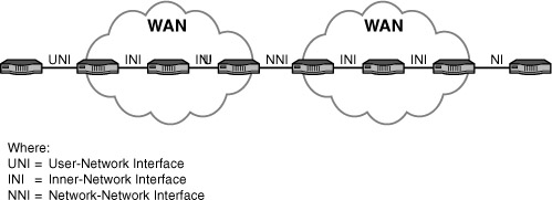
To organize our analysis, we begin with Layer 1, followed with Layer 2. We precede these tasks with an important detour to examine the communications interfaces we have from our homes, home offices, and enterprise locations to and from the WAN. It is called the user-network interface (UNI). Equally important, we examine the interface between network nodes inside the WAN, called the inner-network interface (INI). As well, we look at the interface between WANs, known as the network-network interface (NNI). The positions of these interfaces are shown in Figure 6.2.
FIGURE 6.2 Positions of the interfaces
The prominent wide area UNIs, INIs, and NNIs are listed in Table 6.1, along with the layer or layers of the Internet/OSI models they occupy; at which interface or interfaces they reside; and the hour or hours in this book where they’re explained. Please note that not all interface options are explained in this book, but we do cover the basics for those you might come across.
TABLE 6.1 Prominent WAN Interfaces
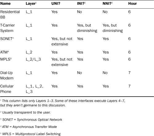
Also, remember this discussion’s focus is on WAN interfaces. Consequently, Ethernet is not included but is examined in several parts of this book. As well, Bluetooth is considered to be a local interface and is not in this table but is explained in Hour 7, “Mobile Wireless Networking.” Wi-Fi, also examined in Hour 7, can be deployed as a LAN or WAN.
Your need to understand the communications operations at the UNI, INI, and NNI will depend on the size of your company, your company’s networking requirements, and its associated geographical scope and scale. For many installations, you will never become involved with these interfaces and you will have no way to access them for their manipulation. Your only access to them will be the passive use of their services. Here are four possibilities of your use of UNI, INI, and NNI operations:
• As one example, perhaps all you need is a DSL service from your home to the Internet. With this scenario, you’ll have no need to use or understand systems such as SONET or MPLS.
• As another example, you might opt for leasing a local phone company’s T-Carrier line from your clinic to a hospital facility located up-state. This UNI might be all you need to purchase, because the phone company is then responsible for any INIs and NNIs that might be used for the end-to-end service.
• As a third example, your company might need a combination of DSL circuits for connection to the public Internet as well as T-Carrier links to set up your own private network, with the ability to interwork these two sets of systems. In this situation, you must come to grips with INI and NNI capabilities.
• At the extreme, perhaps you’re affiliated with a Fortune 500 company, with offices, stores, and so on placed around the globe. This scenario likely puts you in a situation in which you need to know (and use) an array of hardware and software at all three interfaces.
Whatever your situation might be, this hour will get you started in the right direction.
Residential Broadband
The term residential broadband was coined a couple decades ago to describe a collection of UNI technologies to overcome the slow speeds of dial-up modems. The word “residential” is not accurate, because these systems operate at both homes and offices. The word “broadband” is accurate, because it describes a high-speed capability. However, “broadband” links are also found at INIs and NNIs.
During the past 20 years, the telephone companies, cable companies, and satellite companies have been vying with each other to capture this market and to eventually place low-capacity modems in the dustbin. This part of the hour provides an overview of them. Be aware that most of these providers offer additional services such as email accounts, data file backups, IP address options, and security.
DSL
DSL is the offering from the telephone companies, using the current telephone wires that are laid throughout a neighborhood. DSL employs advanced hardware as well as sophisticated signaling and coding techniques to increase the line’s capacity from 256 kilobits per second (Kbps) to several megabits per second (Mbps), depending on the specific offering (and price). In addition, DSL divides the bandwidth (the frequency range) to permit the simultaneous use of the link for more than one telephone call, fax session, Internet surfing, and so on. The exact capacity again depends on the specific offering and associated price.
When DSL came into the market in the 1990s, many customers found it to be complex, unwieldy, and error prone. I thought DSL problems were mainly ones of the telephone companies debugging their products, getting their staff trained with help desks in place, and having user-friendly documentation printed. Today, DSL can be installed by almost anyone who can read a two-page brochure. Therefore, we won’t spend unnecessary time on DSL.
Without question, DSL was sorely needed. Its success has spurred the use of computer networks almost beyond belief. My only recommendation to you if you are a small office or residential user is to make sure you follow the instructions regarding the placement of filters on all phone devices. (They prevent unwanted signals from interfering with each other.)
For larger installations, you will likely be given more options for using the DSL links. One option that might be available in your area is called Asymmetric DSL (ADSL). This variation is so-named because it supports different data rates (in bps) on the two directions of a DSL link. If you have more data streaming down to your site than going up from your site, ADSL will likely be an effective option for your UNI connections. Also, ATM (discussed shortly) provides the potential for substantially enhanced services. DSL routers can enhance security and configuration alternatives (by using Point-to-Point Protocol [PPP] and Challenge Handshake Authentication Protocol [CHAP], discussed in Hours 8 and 20). The DSL router also runs IP and thus provides you with IP addressing, which your ISP manages for you.
Cable Modem Services
The cable TV companies offer a competitive service to DSL. Like DSL, the cable modem products have been very successful. Most of the information just written about DSL also pertains to cable modem services. One notable exception is how cable TV provides conventional telephone service.
Comcast and other CATV firms do not have access to the telephone wires and end offices. To get telephone service, a subscriber can subscribe to a third party for Voice over IP (VoIP). Other cable companies provide a VoIP product based on PacketCable, with one piece of additional equipment named the Embedded Multimedia Terminal Adapter (EMTA). If you opt for computer networking via cable, check out these two technologies, both for price and quality of service (QoS). And if you want to know more about VoIP, take a look at another of my books, Voice over IP.
Satellite Services
Satellite services are available in a range of products and speeds. Two U.S. satellite carriers are in this business: HughesNet and Wild Blue. They provide several speeds from the network to your site (download) of rates from 1Mbps to 3Mbps and upload speeds ranging from 128Kbps to 300Kbps. This capacity difference in each direction of transmission is called asymmetrical bandwidth.
The lower-capacity upload speed from your site to the Internet should not pose a problem if you fit the mold of an average data communications user (receiving much more traffic than you send). However, if you have applications needing high throughput and low delay, the uplink channel might be too slow.
![]()
In Hour 7, we look at other wireless options, beyond these conventional asymmetrical channels, which you might be able to install without the intervention of a communications carrier.
Layer 1 WAN Carrier Systems: T1 and SONET
The most prominent components at the physical layer of WANs are known collectively as the “T1” and “SONET” carrier systems. (These technologies have slightly different implementations and names in non-North American countries.) They can be deployed as user links to the WAN at a UNI, but they are more commonly used inside the network between the network nodes (INI) or between networks (NNI). Both technologies are designed to provide the following services:
• Define the specifications for the media, such as the dimensions of copper wire, the light reflective properties of optical fiber, and the frequencies to be used for wireless channels.
• Define the characteristics of the signals representing the data (1s and 0s) in the form of electrical, electromagnetic, or optical images. Examples are permissible voltages for a copper wire, frequency bands for wireless links, and light intensity for an optical cable.
• Establish rules for the synchronization of the signals between the sending node and the receiving node, such that the receiver “knows” exactly when a 1 or 0 is arriving.
• Provide conventions on how thousands of users’ packets are combined (multiplexed) into a payload (a fancy name for a larger packet) on the media, how they are added to the payload, and how they are dropped off at the final WAN node destination.
• Stipulate the procedures for recovering from faulty lines (such as a backhoe severing a cable) and diverting the affected payloads to a functioning link. These payloads are not diverted based on an individual IP address. Rather, the diversion and recovery are based on hundreds of user packets, which have been multiplexed into larger packets.
• Notify network personnel about problems and their severity (such as sending an “alarm” packet to a network control center about a radio signal experiencing distortion because of an electrical storm).
These services are vital to the health of communications networks. Without them, computer-based business and private correspondences would cease to operate. We take them for granted, but they’re essential to our professional and personal lives.
Unless you’re responsible for a large network, you won’t become involved in these operations. If you’re in charge of your company’s communications links to, say, AT&T, you should have an understanding of these WAN physical carrier systems. For home and small office networks, your principal concern is the integrity of your link to the nearby WAN gateway. That link is usually a broadband connection to a local carrier (a DSL; perhaps a T1 line). It’s the responsibility of this carrier, such as Verizon, to provide you, a paying customer, a link of high integrity.
The next section provides an overview of T1 and SONET. For more details, check out SONET and T1: Architectures for Digital Transport Networks, written by yours truly and Sharleen Waters.
T1
The T1 carrier family has been the North American mainstay for leased (private) lines for over 40 years, which is an extraordinary span of time for a technology to stay relevant in this information age. The word “family” is used because the term T1 is the handle used to describe several options, which are explained shortly.
T1 is installed in many companies, ranging from large banks to small hospitals. It’s a proven, well-understood technology. T1’s staying power is also attributable to its provision for high-speed, reliable links from a company’s office (say, a medical facility) to another office (say, a hospital).
One more point about T1. Some vendors and literature use the initials “DS” (for digital signaling) in place of the “T.” For example, DS1 is used instead of T1. Strictly speaking, the T aspect of the technology refers to the signals themselves, and the DS refers to the way they’re formatted to create units of traffic—that is, how they’re “framed” on the channel. Thus, you might come across the term T1 frame. It’s nothing more than a packet of bits, but with another name.
Synchronization of Signals
One of the most important functions of OSI Layer 1 is synchronizing the signal from the sending machine to the receiving machine. With proper synchronizing (or timing) the receiver knows exactly when to examine the line for the presence of an incoming 1 or 0. The T1 system was designed with the expectation that nodes in digital networks (such as multiplexers) might use different clocking sources to govern their synchronization timings. For example, one network might operate with a different clock than another network. As a consequence of this approach, T1 networks are said to be asynchronous systems, meaning the signals in the network don’t necessarily operate at the same clocking rate.
Because of this design, T1 networks expend considerable resources to devise clever ways to synchronize traffic flowing between the network machines. In so doing, T1 might add or subtract extra bits to compensate for clocking disparities. These schemes make for awkward payload management. Because of the asynchronous nature of the T1 technology, the industry is migrating to an improved scheme, SONET, which is described in the next section.
The T1 Hierarchy
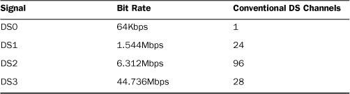
Table 6.2 provides a summary of the T1 family of carrier systems. Again, the more accurate term for a signal is “DS,” which is used in this table. Notice the number of “conventional” voice channels each T1 hierarchy can support. The term “conventional” is used because, in the old days, 64Kbps was the nominal rate for digitized voice. Today’s advanced voice digitization technology can produce a high-quality voice signal with 16Kbps. In deference to legacy, T1 is still quoted with 64Kbps rates.
TABLE 6.2 The T-Carrier Family
Possible Uses for T1 Lines
Although T1 lines were designed for digital phone services, not all trunks carry data. A T1 line, for example, can carry up to 24 separate voice phone lines (or even more, if advanced coding techniques are used). Alternatively, it can carry up to 1.544Mbps of data. Another possibility is the use of 12 voice channels (half the available channels); the remaining bandwidth (about 768Kbps) is used for data.
These and other possibilities are available through your local phone provider. The difference between the kinds of services is based on their use, not from any inherent differences in T1 implementations. All the aforementioned services can be carried over the same type of line. That’s why knowing a bit about T1 technology is useful before you begin to order a communications line for your WAN.
Provisioning Trunks
When you order a line (also called a trunk) from your local phone company, the technical staff will ask how you want to provision it. Depending on your applications, you might want the trunk for voice traffic, data, video traffic, or some combination of the three. For small- to medium-sized operations, you normally will be using either part of a T1 (fractional T1) or a full T1. Larger WANs or offices with high-bandwidth requirements often require T3 (DS3) lines, which can support almost 45Mbps transfer rate.
Leased Lines
When you purchase fractional or full T1 data services from a telephone company, you might be provisioned with a circuit that carries data between two specific points. Those points can be two of your offices; alternatively, one end could be your office and the other could be an ISP. As mentioned, these facilities are often called leased lines because we rent or lease them from the carrier, and no one else’s traffic is allowed to be transported across these “private” lines.
SONET
T1 continues to serve the industry well. But it’s an old technology and is based on communications concepts devised in the 1960s. SONET is designed to enhance (and eventually replace) T1. Think of T1 as a first-generation WAN carrier system and SONET as a second-generation system. I use the term “WAN,” but nothing precludes T1 or SONET from being deployed in a local environment, such as a business or hospital campus.
In addition to providing T-Carrier services, SONET does the following:
• Uses clocks referenced to a common and stable reference, which obviates the cumbersome schemes of trying to synchronize different timing systems.
• Employs highly efficient “grooming” methods for adding, segregating, and dropping user payloads within the SONET super-packet. (“Super” meaning it contains payloads from many users.)
• Has successfully encouraged vendors to use the same conventions, such that a network can be set up with equipment from different manufacturers. Conceptually, T1 could do the same, but its history discouraged this convergence.
• Provides a rich array of network management tools as well as extensive procedures for network recovery. Again, T1 could have done the same, but vendors developed their proprietary schemes before any T1 “standards” bodies could publish such conventions.
• Takes advantage of the high transmission rates of optical fiber.
Like T1, SONET is organized by a multiplexing hierarchy, based on a bps rate and the number of user payloads combined into a SONET frame—the term used for a super-packet. Table 6.3 provides a summary of the SONET hierarchy. (Note: The optical carrier (OC) signal can also be an electrical or electromagnetic signal, in which case the initials of OC can be substituted for STS [Synchronous Transport Signal]).
TABLE 6.3 The SONET Hierarchy
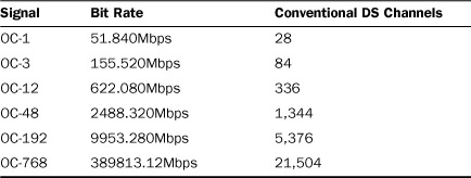
Because of the limitations of T1, SONET is now the prevalent WAN carrier technology used inside the WAN network cloud. Typically, if you lease a T1 or T3 line from a carrier, this traffic is repackaged at the carrier’s site and multiplexed into SONET frames for transport across the WAN.
Layer 2 for WANs: ATM and MPLS
The most prominent components at the data link layer (Layer 2) of WANs are the ATM and MPLS.
ATM
To understand why ATM is used in computer networks, and to understand why it has achieved wide use, please refer back to Figure 5.2 in Hour 5, “Network Concepts.” Recall that the Layer 3 IP address is the most widely used address in the data communications industry. Also, the Layer 2 Ethernet address is employed only in LANs and therefore is of no use in a WAN. Thus, as Figure 5.2 suggests, the IP packet with its source and destination addresses are the only means available to route traffic from one computer to another. If you aren’t assigned an IP address by your ISP (which of course, you are), you’re as helpless as a postal patron without a postal address.
However, as explained in Hour 3, the IP address of 32 bits has proven to be cumbersome and inefficient. Because hundreds of thousands of IP addresses are now in use (with a theoretical base of about four billion), it becomes an impossible task for a router to store even a small percentage of these IP addresses in its routing table. Even with classless IP addressing, also explained in Hour 3, routing with IP addresses is too slow and awkward.
Interestingly, ATM addresses the IP addressing problems by not using addresses! Instead, ATM places the IP packet inside the user data field of an ATM protocol data unit (PDU), which is called a cell (not to be confused with a mobile phone cell; they have no relationship to each other). Then ATM routes the IP packets though the WAN by using labels that have been placed in the ATM cell header. Unlike an IP address, an ATM label has no network association, nor a node associated with a network. In fact, it has no relationship to any location, until the WAN associates it with such. Stay with me; I promise this seemingly strange concept makes good sense.
Let’s use the postal address as an example of a label. First, a street address and a city and state have location significance. They’re bound to geography. But a ZIP Code is not bound to a locality, until the post office so designates. For example, a ZIP number for, say, Los Angeles, can just as easily be associated with another location. Thus, a label is free from an association with a specific physical node until a label-switching node has mapped the label number to this node. Second, with the use of only one label, traffic for all the computers in an office can be reached, because the network has associated a label number (perhaps label 334944) with the gateway router at a specific office complex.
Taking this hypothetical system as an example, even though thousands of IP users may reside on your LANs in your headquarters, each with an IP address, a WAN router may store only one entry in its forwarding table: that of label number 334944. Consequently, instead of a router having to store thousands of IP addresses about your company at the Los Angeles gateway router, it need store only one label. This concept aggregates multiple addresses to one label. It’s a powerful technique for improving the operations of relaying traffic through a network.
Here’s another beauty of label forwarding versus IP address forwarding: After the traffic reaches the final WAN node, such as a router, the software strips away the ATM header and its label. It has done its job by getting the traffic to the gateway router that’s connected to the LANs in your organization. Recall that residing in the ATM data field is the IP packet, with its intact destination and source IP addresses.
Thereafter, IP takes over and Layer 3 (in concert with Layer 2’s Ethernet) is now used to route the data to the computer that’s attached to one of the LANs in your office. If you have a T1 link or a DSL line going to your office or home, it’s likely that ATM is responsible for getting the IP packet all the way to that router sitting in your office—perhaps on your desk. If you take the time to examine the user manuals for your DSL or T1 services, chances are good they will reference ATM labels. They’re called by cryptic names (VPI or VCI), but these monikers are nothing more than fancy names for a label.
Creating a Connection in the WAN
ATM sets up a two-way path in the WAN for a user’s packets to traverse during the user session. This idea is similar to a telephone network setting up a connection for a phone call. However, the ATM network nodes are quite intelligent and have the capacity to find the most efficient and reliable end-to-end path for the user’s specific needs. Although the creation of this connection might entail a short delay before the users can begin their respective transmissions, a “circuit” can be premapped and set up permanently. The idea is similar to a leased line in the T1 world, which is often called a “permanent circuit.” In the ATM network, the guaranteed resource is always there. It might not be an established end-to-end such as that of a point-to-point leased line service. But the network provider is obligated to provide the user with the illusion of a permanent circuit. (And the provider had better be sure that it has sufficient capacity to meet unexpected bandwidth requests!) This concept is called a permanent virtual circuit.
In earlier discussions, we learned how IP addresses are advertised and then used by routers to forward traffic. For label-switching networks, an additional task correlates a label to an IP address and the location of the node with this address. Thereafter, when a router receives IP packets, it maps the destination IP address to the appropriate label. Then only labels are used for forwarding until the IP packet reaches the final destination.
Critical Network Ingredients: Quality of Service (QoS) and Traffic Engineering (TE)
From its inception, ATM was designed to provide network managers with extensive quality of service (QoS) and traffic engineering (TE) operations. Most WAN label-switching networks have implemented an ATM traffic-engineering feature for controlling the amount of traffic users are allowed to send into the network. For example, my ISP monitors the number of bytes my network sends during a window of time. If my network exceeds a predefined limit, the traffic is “throttled” at my LAN site. This monitoring tool prevents the WAN from becoming congested. The idea is similar to the stoplights installed at the traffic ramps onto freeways. The difference is that the traffic ramp apparatus flow-controls all users of the traffic ramp (as a group), whereas ATM traffic engineering controls each user. In a manner of speaking, each user’s packets are controlled by a specific traffic light and a traffic ramp.
In addition, ATM permits a user to request a certain QoS from the network. For example, if Tommy and I are putting together a fancy video show, with the requirement for low delay and high throughput, I can request my ATM network provider to guarantee Tommy and me a certain level of service to meet the requirements for our program.
Notwithstanding all these fine features, if your network is to interact with a wide area ATM network, and you think you or your users will need QoS features, make certain your network provider has provisioned these capabilities in its product. ATM is quite powerful from the TE and QoS standpoints. But most of the ATM operations are optional, and a network might not have them coded in its software.
The ATM Cell
The ATM PDU (the cell) is quite small—only 53 bytes, with 5 bytes used by the ATM network for the label and other control functions. Consequently, most user traffic must be segmented and placed in more than one ATM cell for transport across a WAN. This small user payload versus overhead is just the tip of the iceberg, because other overhead bytes consume some of the remaining 48 bytes to properly identify the user traffic segments in each cell. Consequently, ATM consumes a lot of the network’s bandwidth. Additionally, most of the QoS and TE services, although admirably powerful, consume a lot of overhead bytes.
The “small cell” idea made sense when ATM was first being designed (about 15 years ago). The conventional 1,500-byte packet incurred excessive queuing delays at network nodes and adversely affected applications requiring short delays, such as voice transmissions. But now, with improvements in CPU and memory speeds, larger packets can be handled without affecting the quality of the transmission.
Nonetheless, ATM is widely used. In spite of its overhead, it provides the computer network industry with a full set of TE and QoS operations and a fast method for routing traffic between end users.
Frame Relay
Prior to the introduction of ATM into the marketplace, the prevailing Layer 2 protocol for WANs was Frame Relay. For a while (in the early 1990s), it held a prominent position in the WAN marketplace. Even though it is being supplanted by ATM, your wide area carrier might provide attractive frame relay offerings. For example, AT&T offers frame reply products in 22 states. Frame Relay is a sound, efficient technology. Keep it on your list of things to check when you are shopping for WAN services.
MPLS
MPLS is similar to ATM in that it uses labels to make routing decisions. It also supports a variety of QoS operations. In conjunction with other Internet standards, MPLS offers a diverse set of TE tools. Given these characteristics, you might ask why MPLS exists. It appears to be a redundant technology vis-à-vis ATM.
If MPLS had been conceived before ATM came along, it is likely that ATM wouldn’t be a factor in WANs. But MPLS wasn’t published as a standard until ATM had begun its commercial deployments. Thus, as of this writing, ATM has a stronger presence in the marketplace than MPLS. But I think MPLS will eventually replace ATM. Here’s why:
• MPLS permits a variable-length packet. The MPLS PDU can vary from a few bytes to several thousand bytes. Consequently, it makes better use of precious bandwidth than ATM does.
• Like ATM, MPLS requires a connection setup operation (and can use the idea of a permanent virtual circuit). However, MPLS provides additional features beyond that of ATM for this operation.
• MPLS has been designed to operate with the Internet architecture and protocols, such as IP. Certainly, ATM also interworks with IP, but not as gracefully as MPLS.
Putting More Pieces Together
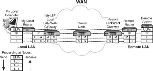
Let’s put a few more pieces into the networking puzzle. We’ll use Figure 6.3 and these abbreviations to help us. Also, notice the legend at the bottom of Figure 6.3, which shows the order of invocation of the layers. The down arrow means transmit; the up arrow means receive.
FIGURE 6.3 Communications end-to-end
IP: The Internet Protocol
E: Ethernet
A: ATM
D: DSL
M: MPLS
S: SONET
T: T1
ULP: Upper-layer protocols
As I key in this paragraph and then send it to a backup server somewhere on the Internet, my sterling verse is sent to a local router (very local—perhaps in my office, or on my desk) via my local Ethernet and the IP packet. In Figure 6.3, my local computer is executing all layers of the Internet model, but we’re only concerned with Layers 1–3. My machine executes IP at L_3, and it executes Ethernet at L_2 and L_1.
At my local router, the Ethernet frame is received through the router’s Ethernet link and sent up to its IP module. Hereafter, Ethernet is not executed until the traffic arrives at the remote server. The destination IP address in the IP packet (the IP address of the remote server) is examined, and the local router’s forwarding table reveals that the packet is to be sent to a “next node,” which is my ISP (shown in the figure as “Local LAN/WAN Gateway”), to eventually reach the remote server.
Notice that my local router and my ISP’s router operate with ATM at L_2 and DSL at L_1. Consequently, the IP packet is placed into ATM cells and sent across the DSL link to my ISP. At this node, it may execute L_3 and look at the destination address in the IP packet. For this example, it does not because my local router has already made a correlation of the destination IP address (the remote server at the other end of the figure) to an ATM label. Thus, my ISP router’s job is simplified because it doesn’t have to deal with IP.
In this example, my ISP has migrated to MPLS for exchanging traffic between network nodes. As seen on its send side, it correlates the ATM label to an MPLS label (and, of course, it strips away all that ATM overhead).
Notice that L_1 is now SONET and remains so during the operations inside the network. If you now trace the Layer 1 configurations on the right side of the figure, you’ll see that the remote LAN/WAN gateway maps the SONET frames into T1 frames for sending to the server’s remote router. Then T1 is stripped away, and Ethernet is re-created for use on the LAN between the remote router and the remote server.
Finally (although all these operations likely took place in less than half a second), the remote server processes the IP packet, which contains my source IP address and the remote server’s destination IP address. The data has arrived!...and usually quickly and error free.
But now what? Thus far, all these extraordinary systems have transported my traffic (my textual paragraph) to the remote server. But this server hasn’t yet executed the upper layers of the model. When it does, my paragraph will indeed be stored on a backup server disk. Notice by the dashed lines that the data, headers, and trailers of the upper-layer protocols (ULPs) are processed only at my local computer and the remote server.
We continue our layered-protocol journey in Hour 15, “Connecting to the Internet: Key Supporting Operations,” by an examination of the top layers, especially Layers 4 (TCP) and 7 (DNS). For Hours 7–14, we assemble more building blocks for the network and add more pieces to the networking puzzle.
Summary
This hour explained the major features of a WAN and why it’s different from a LAN. The key components of a WAN were examined, as were the three key WAN interfaces. Also explained were the principal WAN L_1 carrier systems and those that make up Layer 2. The pros and cons of address and label switching were highlighted. The hour concluded with a look at how a packet is sent through a WAN between two LANs and how the WAN’s carrier systems and protocols contribute to this transport.
Q&A
Q. Contrast a WAN with a LAN.
A. The WAN is usually a public network; the LAN is a private network. A WAN spans greater distances than a LAN and employs more expensive and higher-capacity L_1 technologies than a local network. Because of these differences, WANs and LANs typically implement different procedures to manage traffic.
Q. Name the three interfaces associated with a WAN.
A. The three WAN interfaces are the user-network interface, or UNI; the inner-network interface, or INI; and the network-network interface, or NNI.
Q. The prominent so-called residential broadband products come in three offerings. List them.
A. Digital subscriber line (DSL), cable modem, and satellite services are the three residential broadband products.
Q. Why was SONET developed to enhance or replace the T-Carrier technology?
A. The T family of carrier systems don’t provide a stable clocking source for the digital images (1s and 0s) traveling across communications links. Thus, proper synchronization of signals is awkward for T technology. In contrast, SONET is a synchronous technology, with highly accurate clocking mechanisms. In addition, SONET has better network management operations and better “grooming” (multiplexing/demultiplexing) capabilities than the T-Carrier technology.
Q. Why is ATM or MPLS employed for relaying traffic in a WAN instead of IP?
A. IP forwarding relies on the IP address, which entails more overhead than label switching. ATM and MPLS use label switching. In addition, ATM and MPLS support more traffic engineering and quality of service (QoS) features than IP does.
Q. Why is Ethernet not employed in a WAN?
A. From its inception, Ethernet was designed to be distance limited because of how its users share a link. Its L_2 protocol limits how far apart the Ethernet devices can be from each other. In addition, the Ethernet (MAC) address is considered to have local significance only and was not designed to be used in a WAN.
Q. If the IP packet is not processed in a WAN, how can IP traffic be sent from one LAN to another, but through a WAN?
A. The IP packet is placed inside another protocol data unit (PDU), such as an ATM cell or an MPLS frame, and sent transparently through the WAN. It is the job of the WAN gateway node or the local sending router to correlate the destination IP address into a label. The WAN then uses this label to transport the IP datagram to the remote user.