
Chapter 26. Embedded and other real-time systems projects
Most of the requirements examples and discussions in the book so far have dealt with business information systems. The world is also full of products that use software to control hardware devices, broadly called embedded systems. Among countless examples are cell phones, television remote controls, kiosks of all sorts, Internet routers, and robot cars. We’ve often used the term system in this book as a colloquial synonym for product, application, or solution, to refer to whatever software-containing thing you’re building. In this chapter, though, system refers to a product that contains multiple, integrated software and hardware subsystems. The software that controls a real-time system can be embedded in the device in the form of a dedicated computer, or it can reside in a host computer separate from the hardware it controls. Embedded and other real-time systems have sensors, controllers, motors, power supplies, integrated circuits, and other mechanical, electrical, and electronic components that operate under software control.
Real-time systems can be classified as hard or soft. Hard real-time systems have rigid time constraints. The operations that the system performs must execute within specified deadlines or bad things happen. Life-critical and safety-critical control systems, such as air traffic control systems, are hard real-time systems. An operation that doesn’t complete on time could result in a collision because of an undetected obstacle. Soft real-time systems also are subject to time constraints, but the consequences of missing the timing deadline during some operations are less severe. An ATM is a soft real-time system. If communication between the ATM and the bank doesn’t complete in the allocated time interval, no one will die if the ATM has to try again or even if the operation terminates.
More than on most software development projects, it’s important to have a good understanding of requirements before getting too far into development on embedded systems projects. Because software is more malleable than hardware, excessive requirements churn that dictates hardware changes is more expensive than comparable volatility on software-only projects. It’s also essential to know about constraints that both hardware and software engineers must respect: physical object sizes; electrical components, connections, and voltages; standard communication protocols; the sequence in which certain operations must take place; and the like. Hardware components that have already been selected for the design impose constraints on those yet to be chosen.
The requirements elicitation techniques described elsewhere in this book are certainly applicable on real-time projects. The same modeling techniques can be used, with some refinements. This chapter addresses some of the special requirements considerations of embedded and other real-time systems.
System requirements, architecture, and allocation
When specifying a complex system, many teams first create a system requirements specification, abbreviated SyRS ([ref124]). The SyRS describes the capabilities of the system as a whole, including capabilities that could be provided by hardware components, software components, and/or humans. It also describes all of the inputs and outputs associated with the system. In addition to functionality, the SyRS should specify the critical performance, safety, and other quality requirements for the product. All this information feeds into the preliminary design analysis that will guide the team when it is choosing architectural components and allocating capabilities to them. The SyRS could be a separate deliverable from the software requirements specification, or the SRS could be embedded within the SyRS, particularly if most of the system complexity lies within the software.
Requirements analysis of a complex system is tightly intertwined with the system’s architecture. Requirements thinking and design thinking become more commingled in real-time systems than in other types of software projects. The architecture represents the top level of design, often depicted by using simple box-and-arrow diagrams, although numerous other architecture modeling notations exist. A system’s architecture consists of three elements:
Components of the system, where a component could be a software object or module, a physical device, or a person
Externally visible properties of the components
Connections (interfaces) between the system components
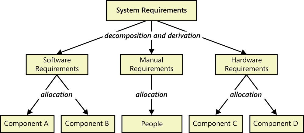
The architecture is developed in a top-down, iterative fashion ([ref178]; [ref110]). The person who takes the lead role in this type of analysis typically is a system analyst, requirements engineer, system engineer, or system architect with a strong technical background. The analyst partitions the system into appropriate software and hardware subsystems and components that will accommodate all of the inputs and produce all of the outputs. Certain system requirements might turn directly into software requirements if software is deemed to be the correct medium for providing a certain capability. In other cases, the analyst will decompose individual system requirements into numerous derived software, hardware, and/or manual requirements to be performed by humans (Figure 26-1). Deriving software requirements from system requirements can expand the volume of requirements several-fold, partly because that derivation generates interface requirements between the components. The analyst allocates the individual requirements to the most appropriate components, iteratively refining the architectural partitioning and the requirement allocations. The ultimate outcome is a set of requirements for each of the software, hardware, and human components that will collaborate to provide the necessary system services.
It’s a good idea to establish requirements trace links between system requirements, derived software and hardware requirements, and the architectural components to which they were allocated. Chapter 29 discusses requirements traceability.
Poor allocation decisions can result in:
The software being expected to perform functions that would have been easier or cheaper for hardware to perform (or the reverse).
A person being expected to perform functions that would have been easier or cheaper for hardware or software to perform (or the reverse).
Inadequate performance.
The inability to easily upgrade or replace components.
For example, performing a certain function in software could require a faster processor than if a specialized piece of hardware were to perform that function. There are always trade-offs. Although software is easier to change than hardware, engineers shouldn’t use that flexibility as a reason to skimp on hardware design. The people who perform the requirements allocation must understand the capabilities and limitations of the software and hardware components, as well as the costs and risks of implementing the functionality in each.
Modeling real-time systems
As with business information systems, visual modeling is a powerful analysis technique for specifying real-time systems. State-transition diagrams or their more sophisticated variants, such as state chart diagrams ([ref151]) and UML state machine diagrams ([ref006]), are particularly relevant. [ref064] gives examples of how to employ use cases and other UML models to represent requirements for real-time systems.
Most real-time systems can exist in multiple states with defined conditions and events that permit transitions from one state to another. State tables and decision tables can be used to supplement or replace state-transition diagrams, often revealing errors in the diagrams. The context diagram (described in Chapter 5) is also useful to show the environment in which the system operates and the boundaries between the system and the external entities with which it interfaces. Architecture diagrams show the partitioning of the system into subsystems with interfaces between them. This section shows some sample models (somewhat simplified, as usual) from an embedded system with which you might have personal experience: an exercise treadmill.
Context diagram
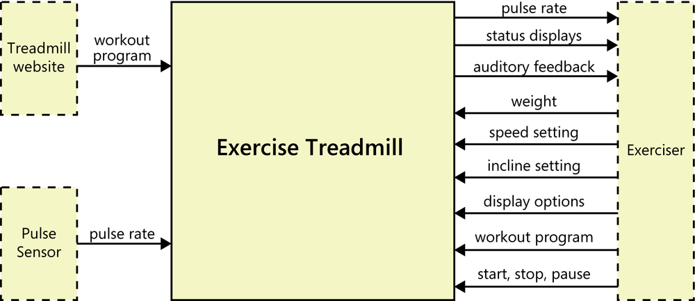
Figure 26-2 illustrates the context diagram for my home treadmill. This notation is slightly different from that used in Figure 5-6, shown earlier in Chapter 5, but the intent and the types of information displayed are the same ([ref151]). Using the large square instead of a small circle to represent the system makes it easier to show multiple input and output flows between the system and a single external entity, such as the Exerciser (the person using the treadmill). The other two external entities are the website of the treadmill’s manufacturer, from which the Exerciser can download various workout programs, and a sensor that measures the Exerciser’s pulse rate. As usual with context diagrams, this model shows nothing of the treadmill’s internals.
State-transition diagram
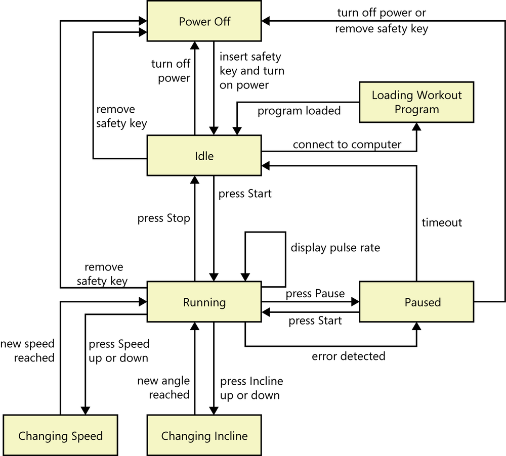
Figure 26-3 shows a state-transition diagram (STD) for the treadmill. Recall from Chapter 12 that the boxes in an STD represent various states that the treadmill could be in, and the arrows represent allowed transitions from one state to another. The labels on the transition arrows indicate the conditions or events that trigger each state change. This diagram shows us more about how the treadmill functions. It also begins to provide some information about the user interface controls needed, such as controls labeled Speed, Incline, Start, Pause, and Stop. Figure 26-3 refers to “pressing” some control, but of course, those controls could be implemented in a variety of ways. [ref151] describe more sophisticated statechart diagrams for representing this kind of information in a richer way.
Event-response table
Event-response analysis provides another way to think about the behavior of a real-time system and hence its functional requirements ([ref250]). As was described in Chapter 12, a system could respond to business events that trigger execution of a use case, signal events such as input from a sensor, and temporal events that cause something to happen after a specified time interval or at a specific point in time. Table 26-1 lists several events and their corresponding responses for the treadmill.
Event | Treadmill state | Response |
Exerciser presses Incline Up button | Below maximum incline | Increase incline by 0.5 degree |
Exerciser presses Incline Up button | At maximum incline | Generate “at limit” audio signal |
Exerciser presses Speed Down button | Above minimum speed | Decrease speed by 0.1 mph |
Exerciser presses Speed Down button | At minimum speed | Stop treadmill belt |
Exerciser removes safety key | Running | Stop treadmill belt and turn power off |
Exerciser removes safety key | Idle | Turn power off |
Exerciser presses Pause button | Running | Stop treadmill belt; initiate timer |
Exerciser presses Pause button | Paused or idle | Generate “error” audio signal |
Timer for paused condition reaches timeout limit | Paused | Go to idle state |
Exerciser presses Start button | Running | Generate “error” audio signal |
Exerciser presses Start button | Paused | Start treadmill belt on current speed setting |
Exerciser presses Start button | Idle | Start treadmill belt at lowest speed |
This event list provides detailed requirements for the treadmill’s functionality that flesh out the high-level view shown in the STD in Figure 26-3. It’s also a great aid for conceiving tests. Even a complete event-response table still leaves plenty of design thinking to be done, such as how many degrees per minute the incline motor will change the belt’s incline, and how quickly the treadmill belt will change from stopped to the set speed. Safety considerations will influence these decisions, too. It would be dangerous for the Exerciser if the belt started, accelerated, or stopped too abruptly.
Embedded systems must manage a combination of event-based functions (as shown in Table 26-1) and periodic control functions. Periodic functions are executed repeatedly while the system is in a particular state, rather than just once upon state entry. An example is monitoring the Exerciser’s pulse rate once every second and adjusting the belt speed in response to maintain a preset pulse rate, if such an exercise program was being used.
Drawing models like this is an excellent way to find missing requirements. I once reviewed a requirements specification for an embedded system that included a long table describing the various machine states, the functionality associated with each state, and possible navigation destinations from each state. I drew a state-transition diagram to represent that information at a higher level of abstraction. In the process of drawing the STD, I discovered two missing requirements. There was no requirement that allowed the machine to be turned off, and there was no provision for the possibility of entering an error state while the machine was running. As you’ve seen before, this example illustrates the value of creating multiple representations of requirements knowledge and verifying them against each other.
Architecture diagram
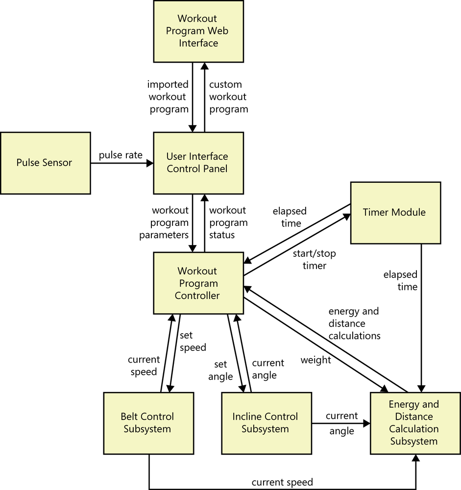
Another type of model that’s useful for these types of systems is an architecture diagram, which is generally part of the high-level design. Figure 26-4 shows a portion of a simple architecture diagram for the treadmill. It identifies the major subsystems that will provide all of the treadmill’s functions, as well as the data and control interfaces between them, at a high level of abstraction. Richer architecture description languages are available, and the Unified Modeling Language (UML) also works well for modeling architectures ([ref208]). The subsystems shown in Figure 26-4 can be further elaborated into specific hardware components (motors and sensors) and software components as architectural analysis proceeds. A preliminary architecture analysis can reveal and refine functional, interface, and quality requirements that might not have been evident from other elicitation activities.
Drawing architecture models during requirements analysis is clearly taking a step into design. It’s a necessary step. Iterating on the architectural partitioning and the allocation of system capabilities to subsystems and components is how an architect devises the most appropriate and effective solution. Further requirements elicitation is needed, though. Functional requirements such as the following will guide the developers in both choosing appropriate hardware components and designing user interface controls:
Incline.Angle.Range The Exerciser shall be able to increase and decrease the incline angle of the treadmill from 0 degrees through 10 degrees, inclusive, in 0.5- degree increments.
Incline.Angle.Limits The treadmill shall stop changing its angle and provide audible feedback when it has reached the minimum or maximum limit of its incline range.
In addition to the functionality represented by the architecture, the treadmill designers must know about the business rules that provide necessary algorithms. An example is calculating the number of calories the Exerciser has burned from the combination of his weight and the workout program, which is a series of segments of specified duration, incline angle, and belt speed. It might seem peculiar to speak of “business rules” in conjunction with an embedded system. However, virtually all of the requirements practices discussed elsewhere in this book apply to embedded and other real-time systems, just as they do to business information systems.
Prototyping
Prototyping and simulation are other powerful techniques for eliciting and validating the requirements for embedded systems. Because of the costs and time needed to build hardware (and perhaps to rebuild it if you discover requirement or design errors), you can use prototypes to test operational concepts and to explore both requirements and design options for the device. Simulations can help you better understand user interface displays and controls, network interactions, and hardware-software interfaces ([ref066]). Keep in mind, though, that the simulation will differ from the real product in numerous respects.
Interfaces
Interfaces are a critical aspect of embedded and other real-time systems. As you saw in Chapter 10 the SRS should address four classes of external interface requirements: user, software, hardware, and communications interfaces. In addition, the partitioning of complex systems into multiple subsystems creates numerous internal interfaces between components. Because embedded systems can be incorporated into other embedded systems as part of a larger product (such as a cell phone integrated into a motor vehicle’s communication system), the interface issues become even more complex. Requirements analysis should concentrate on the external interface issues, leaving the internal interface specifications for architecture design.
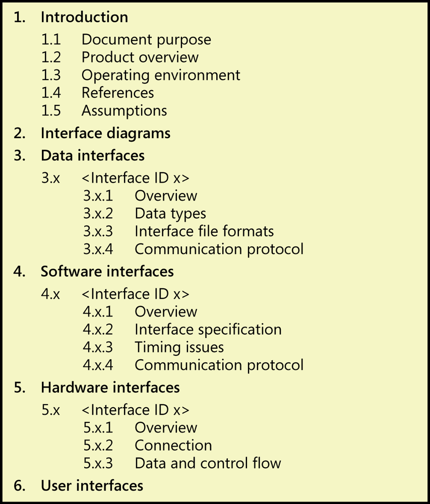
If your external interfaces are relatively simple, you can specify them as described in 5. External interface requirements of the SRS template illustrated in Figure 10-2, shown earlier in Chapter 10. Projects that are building complex systems often create a separate interface specification to document these critical aspects. Figure 26-5 suggests a template for an interface specification document that can accommodate both external and internal interfaces.
Timing requirements
Timing requirements lie at the heart of real-time control systems ([ref141]). Undesirable outcomes can result if signals are not received from sensors as scheduled, if the software cannot send control signals to the hardware when anticipated, or if the physical devices do not perform their actions on time. Timing requirements involve multiple dimensions:
Execution time. The execution time for a specific task is the elapsed time from when it is initiated to when it completes. This can be measured as the duration between two specific events that bound the task’s execution.
Latency. Latency is the time lag between when a trigger event occurs and when the system begins to respond to it. Excessive latency poses a problem in, for example, music recording and production software, in which multiple prerecorded and live audio tracks must be precisely synchronized.
Predictability. Predictability refers to the repeated, consistent timing of a recurring event. Even if the timing is not especially “fast,” events often have to be performed at precise intervals, as when sampling an incoming signal. Digitizing an audio waveform often is performed at 44,100 cycles per second. The sampling frequency must be predictable to avoid constructing a distorted digital representation of the analog waveform.
Some issues to explore regarding the timing and scheduling requirements for a system’s real-time tasks are:
Periodicity (frequency) of execution of the tasks and their tolerances.
Deadlines and tolerances for execution of each task.
Typical and worst-case execution time for each task.
Consequences of missing a deadline.
The minimum, average, and maximum arrival rate of data in each relevant component state.
The maximum time before the first input or output is expected after a task initiates.
What to do if data is not received within the maximum time before the expected first input (timeout).
The sequence in which tasks must run.
Tasks that must begin or end execution prior to other tasks beginning.
Task prioritization, so you know which tasks can interrupt or preempt others, and on what basis.
Functions that depend on what mode the system is in (normal mode versus firefighter service mode for an elevator, for example).
When specifying timing requirements, indicate any constraints and the acceptable timing tolerances. Understand the distinction between soft and hard real-time demands for your system so you don’t specify overly stringent timing requirements. Those can lead to over-engineering the product at excessive cost and effort. If the timing tolerances are broader, you might be able to get away with using less expensive hardware. As [ref141] points out, “Real-time performance is seldom about being as fast as absolutely possible. Rather, it is about being just as fast as you need to be, and minimizing overall cost.”
Specifying the timing requirements for the system involves understanding the deadlines for time-critical functions. It entails scheduling both sequential and concurrent functions to achieve the necessary performance within the constraints of processor capacity, input/output rates, and network communication rates. One team used a project-scheduling tool to model the timing requirements for an embedded product, working at the millisecond time scale rather than in the more traditional days and weeks. This creative and unconventional use of a modeling tool worked very well. In some cases, the timing and scheduling algorithms to be used might be imposed through requirements in the form of design constraints, but more frequently these will be design choices. [ref136] offer a valuable overview of scheduling issues for real-time systems.
Quality attributes for embedded systems
Quality attribute requirements are especially critical for embedded and real-time systems. They can be vastly more complex and intertwined than those for other software applications. Business software is generally used in an office where there is not much variance in the environment. In contrast, the operating environment for embedded systems could involve temperature extremes, vibration, shock, and other factors that dictate specific quality considerations. Quality categories that are likely to be particularly important include performance, efficiency, reliability, robustness, safety, security, and usability. This section discusses some of the particular aspects of these quality attributes that you need to explore carefully during elicitation of requirements for such systems.
In addition to the software quality attributes that were discussed in Chapter 14 embedded systems are subject to quality attributes and constraints that apply only to physical systems. These include size, shape, weight, materials, flammability, connectors, durability, cost, noise levels, and strength. All of these can dramatically increase the cost and effort needed to validate the requirements adequately. There could be business and political reasons to avoid using materials whose supply might be threatened by conflict or boycott, causing prices to skyrocket. Other materials are best avoided because of their environmental impacts. Avoiding the use of optimal materials could lead to trade-offs in performance, weight, cost, or other attributes.
It can be difficult and expensive to build in desired quality characteristics after the hardware design is complete, so address these requirements early during elicitation. Because quality characteristics often have a profound impact on a complex product’s architecture, it’s essential to perform the attribute prioritization and trade-off analysis before getting into design. [ref141] presents a good discussion of nonfunctional requirements that are especially important for embedded systems development. Chapter 14 presented many examples of these and other quality attribute requirements.
Performance The essence of a real-time system is that its performance must satisfy the timing needs and constraints of the operating environment. Therefore, all processing deadlines for specific operations must be included in the requirements. However, performance goes beyond operational response times. It includes startup and reset times, power consumption, battery life, battery recharge time (as with electric automobiles), and heat dissipation. Energy management alone has multiple dimensions. How should the system behave if the voltage drops momentarily, or under a particularly high current load during startup, or if external power is lost and the device must switch to battery backup power? And, unlike software, many of these components can degrade over time. What are the requirements for how long a battery maintains a given profile of power over time before it needs to be replaced?
Efficiency Efficiency is the internal quality counterpart to the externally observable attribute of performance. Efficiency aspects of embedded systems focus on the consumption (and hence the remaining availability at any moment) of resources including processor capacity, memory, disk space, communication channels, electrical power, and network bandwidth. When you are dealing with these matters, requirements, architecture, and design become tightly coupled. For instance, if the total power demand of the device could exceed the power available, can the device be designed to cut power to components that don’t need it all the time, thereby making more power available to other components or services?
The requirements should specify the maximum anticipated consumption of various system resources so designers can provide sufficient slack resources for future growth and unexpected operating conditions. This is one of those situations for which concurrent hardware and software design is vital. If the software is consuming too much of the available resources, the developers must resort to clever tricks to work around those limitations. Choosing more capable hardware up front offers a much less costly solution than fine-tuning the software components ([ref141]).
Reliability Embedded and other real-time systems often have stringent reliability and availability requirements. Life-critical systems such as medical devices and airplane avionics offer little room for failure. An artificial cardiac pacemaker that’s implanted into a patient’s body must be expected to work reliably for years. If the product fails or the battery goes dead prematurely, the patient can die too. When you are specifying reliability requirements, realistically assess the likelihood and impact of failure so you don’t over-engineer a product whose true reliability requirements aren’t as demanding as you might think. Increasing reliability and availability comes at a price. Sometimes you need to pay that price; sometimes you do not.
Robustness Robustness has to do with how well the system responds to unexpected operating conditions. There are several aspects to robustness. One is survivability, which is often considered to apply to devices in use by the military but has everyday applications as well. A good example of embedded systems designed for high survivability are the aircraft “black boxes,” electronic recording devices that are designed to survive the horrific trauma of an airplane crash. Actually bright orange and technically called the flight data recorder and the cockpit voice recorder, these devices are built to withstand an impact of 3,400 times the force of gravity, fires, immersion in water, and other hazards. Not only must the physical container retain its integrity under such extreme conditions, but the data recording devices inside must still be intact and readable.
Other aspects of robustness have to do with how the system deals with faults, or exceptions, that occur during execution and can lead to system failures. Both hardware and software faults can lead to failures. I once attempted to withdraw $140 from an ATM. The ATM gave me a receipt for $140, all right, but it only gave me $80 in cash. I waited 15 minutes while a bank employee rooted around in the back of the ATM; then she handed me my $60. Apparently there was a mechanical failure: several bills were stuck together and jammed the exit slot. Besides the fact that I wasted some time, I was concerned because the ATM thought the transaction had gone just fine—it never detected the problem.
There are four aspects to how systems handle faults ([ref141]):
Fault prevention. Ideally, the system will prevent many potential fault conditions before they can cause a failure. That’s the idea behind having software systems test preconditions before initiating the execution of a use case.
Fault detection. The next-best course of action is to detect a fault as soon as it occurs. This is why requirements elicitation must explore exception conditions, so developers can anticipate possible errors and devise ways to look for them.
Fault recovery. If the system detects an anticipated fault, it should have mechanisms defined for responding to it. Requirements development should not only identify potential faults but also specify how they should be handled. Sometimes the system can retry an operation, as with an intermittent communication interruption or a timeout that might work fine the next time. Systems are sometimes designed with failover mechanisms. If a fault causes the system to fail, a backup system takes over the operation. In other cases, the system must terminate the operation, perhaps shutting down or restarting in some way that minimizes the negative impact on the user. As an example, if your car’s antilock brake system (ABS) detects a faulty sensor, it might shut down the ABS, illuminate a warning light on the dashboard, and log that information in the car’s computer for future diagnosis and repair. Which leads us to…
Fault logging. The system should retain a history of faults that it detects and what happened as a consequence. This information is useful for diagnosing what’s wrong and can help a maintenance person detect patterns that lead to problems. For instance, a fault history might indicate a defective hardware component that should be replaced. Modern automobiles contain an on-board diagnostics system. A technician can plug a cable into this system and retrieve a history of events in the form of standardized codes that report what malfunctions occurred.
The designers of my treadmill recognized that under certain conditions the treadmill can be jammed in a position in which the incline angle cannot be lowered to zero. The user manual describes a (rather tricky) manual operation I can perform to reset the treadmill so it again has the full range of incline angles available. It would have been even better had the manufacturer designed the treadmill so that it was impossible for this jam to take place, if feasible. Sometimes, though, providing a workaround for a low-probability and low-impact failure is cheaper than designing the system to completely prevent the failure.
Safety Any system that contains moving parts or uses electricity has the potential to cause injury or death to a human being. Safety requirements are vastly more significant for real-time systems than for information systems. Numerous books have been written on software and system safety engineering, so we will not attempt to recap all of that vital information here. Good sources are [ref160], [ref107], [ref141], and [ref102].
Begin your investigation of safety requirements by performing a hazard analysis ([ref067]; [ref069]). This will help you discover the potential risks that your product could present. You can rate them by their probability of occurrence and the severity of occurrence, so that you can focus on the most serious threats. (Chapter 32 discusses risk analysis further.) A fault tree analysis is a graphical, root-cause analysis technique for thinking about safety threats and what factors could lead to them ([ref068]). This allows you to focus on how to avoid specific combinations of risk factors materializing when your product is in use. Safety requirements should address the risks and state what the system must do—or must not do—to avoid them.
Hardware devices often include some kind of emergency stop button or dead man’s switch that will quickly turn the device off. The exercise treadmill had a safety requirement something like the following:
Stop.Emergency The treadmill shall have an emergency stop mechanism that brings the belt to a halt within 1 second when activated.
This requirement led to the design of a flat plastic key that must be inserted in the front of the treadmill before the treadmill can be powered up. Removing the key cuts the treadmill power, stopping the belt motion quickly. A lanyard attached to the key can be clipped to the Exerciser’s clothing to pull out the key if the Exerciser slips or falls off the treadmill. It works!
Security The security of embedded systems is under much discussion these days because of concerns about cyberattacks that could take over, disrupt, or disable power plants, railroad control systems, electrical distribution grids, and other critical infrastructure. Theft of intellectual property from the memory of embedded systems is also a risk. An attacker could potentially reverse engineer code to learn how the system works, either to copy it or to attack it. Protecting embedded systems involves some of the same security measures that host-based information systems need. These include the following ([ref141]):
Secrecy, primarily through encryption
Authentication, to ensure that only authorized users can access the system, typically provided through passwords (with all the human failings that involves)
Data integrity checks, to try to discover whether the system has been tampered with
Privacy of data, such as protecting against unauthorized tracking of users through their handheld GPS devices
In addition, though, embedded systems are subject to other types of specific attacks. These include attempts by users to take over control of the system; interception of electronic communications, particularly wireless communications; and the insertion of malicious software updates, sometimes through social engineering of gullible users (many of us fall for that trick from time to time). The full scope of security considerations for embedded systems is large, and it is a very serious concern (ref007). [ref141] and [ref140] offer many suggestions for how to make your embedded products more secure.
Usability Many embedded systems include some kind of human-computer interface. The general principles of software usability apply, but other aspects of usability might be important when a person is using a physical device in the field as opposed to a keyboard in the office. Recently, I switched from using a mouse designed for right-handed users to a symmetrical one. I keep inadvertently hitting the right mouse button with the ring finger on my right hand. This wastes my time and can lead to undesired system responses.
Display screens on products to be used outdoors must accommodate different lighting situations. I once had an account at a bank whose drive-up ATM was located such that the LCD screen was completely unreadable when sunlight hit it at certain angles. As another example, I cannot read the display on my digital wristwatch when I’m wearing polarized sunglasses unless I rotate my wrist to just the right angle, because LCD displays are themselves polarized.
Some usability constraints are imposed by legislation such as the Americans with Disabilities Act, which requires certain systems to provide accessibility aids for people who have physical limitations. Embedded systems must accommodate users having different degrees of:
Audio acuity and frequency response (consider when designing audio feedback and prompts).
Visual acuity and color vision (consider the use of color and text size in visual displays).
Handedness and manual dexterity (affects the user’s ability to press small buttons accurately or to navigate using a touch screen).
Body size and reach (keep the user profile in mind when establishing the physical positioning of controls, displays, and equipment).
Native languages (important for devices controlled by speech recognition).
The challenges of embedded systems
Embedded and other real-time control systems offer a unique set of challenges that software-only applications do not. The basic principles and practices of requirements elicitation, analysis, specification, and validation apply to both classes of products. Embedded systems require taking a systems engineering approach so that developers do not optimize either software or hardware components at the expense of the other and to avoid ugly integration problems. Architecture and design choices are more tightly linked with requirements analysis than in software-only systems, partly because it is so much more expensive to change hardware after it has been designed or manufactured. Embedded systems present a different emphasis of constraints and quality attributes than do software-only systems, and often they are more interwoven with operating system considerations as well. Careful specification of system requirements, software requirements, hardware requirements, and interface requirements will go a long way toward making your embedded and other real-time development projects successful.