12
Achieving Perfect Exposures
Correct exposure in any lighting situation is best determined with an exposure meter, which can be a separate handheld meter or one built into the camera system. All metering systems produce good results if used properly. It is therefore essential that you learn in detail how the different metering methods work, how the different meters measure the light, and how they must be used to provide the correct results with any subject in any lighting situation.
There are two methods of exposure metering. You can measure the light that falls on the subject, known as incident light metering, or you can measure the light that is reflected off the subject or scene, known as reflected light metering.
THE INCIDENT LIGHT-METERING APPROACH
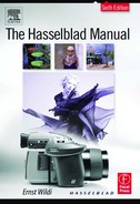
An incident meter reading is taken by a measuring cell covered with a domelike diffusion disc that measures the light falling on the subject from all directions. Such a diffusion disc is found on top of the Hasselblad PME 90 and PME 45 viewfinders, the only two items in the Hasselblad system made for incident meter readings (see Figure 12-1). To use handheld light meters for incident light readings, you usually slide or attach a diffusion disc over the measuring cell.
You take incident meter readings by holding the meter in front of the subject or in another location that receives the same amount of light as the subject, with the metering cell facing the camera lens. In this position all the light that falls on the subject also falls on the metering cell. In some cases, such as with a strong sidelight, you may want to compromise and have the cell face in a direction between the camera and the main light. Incident meter readings of backlit subjects are problematic, but for backlit landscapes where the ground covers a large part of the composition, try holding the meter flat over the ground with the meter cell pointing toward the sky.
Because incident meter readings usually have to be made where the subject is, the photographer must move away from the camera. Light metering can become a time-consuming, impractical process, especially in handheld photography.
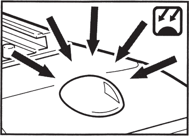
Figure 12-1 The PME incident metering cell The PME 90 and PME 45 meter prism view-finders have the incident metering cell covered by a domelike fixture on top of the view-finder. The cell measures the light falling on the subject from all directions.
Incident meter readings, however, have the wonderful advantage of being unaffected by the color and brightness of the subject. The incident meter measures only the light that falls on the subject, giving the same reading whether held in front of a white, gray, or black subject. The reading of an incident meter is correct regardless of the color or brightness of the subject.
Using the Incident Meter on the PME Prism Viewfinders
Incident meter readings with the PME 90 and PME 45 must be made in the same way as incident meter readings, with a handheld incident meter. The measuring cell, the dome, must be held in front of the subject being photographed or in a place that receives the same amount of light as the subject. The dome must face toward the camera lens (see Figure 12-2). You can take the meter reading with the finder on the camera, an approach I have found most practical, or you can remove the finder for the reading, leaving the camera set up on the tripod.
Hold the meter prism finder (or the camera with the finder) so that the measuring dome is more or less parallel to the subject and is pointing toward the position from where the picture will be taken. Make certain that you do not shade the measuring dome. Press the metering button to set the meter reading which also locks it automatically. You can now take all the time you wish to read the metered value in the viewfinder and make the appropriate lens settings.

Figure 12-2 Using the PME incident meter An incident meter reading with the PME meter prism finders must be made in the same way as an incident reading with a handheld meter. The metering cell is pointed toward the camera from a position where it measures the light falling on the subject from all directions.
REFLECTED METER READINGS
Reflected meter readings are usually more practical, in location and handheld photography, because the meter reading can be made from the camera position. This is true whether the reading is taken with a handheld meter or a built-in metering system. With a metering system built into the camera, the reading can be more precise and definitely much faster.
In a reflected meter reading, we no longer measure the light falling on the subject; instead, we are measuring the light reflected off the subject. The meter reading, with the meter pointed at the subject, is now determined not only by the amount of light falling on the subject but also by the amount of light reflected from the subject. A bright subject gives a higher reading than a dark one even if the same amount of light falls on both. The difference between light and dark colors can amount to four or five EV values or f stops (see Figures 12-3 and 12-4). This fact applies to a handheld reflected meter as well as exposure meters built into a camera system, as in the Hasselblad H, XPan, and 200 model cameras, or when a meter prism finder is used on any V system camera.
Light Reflectance and Gray Tones
Although the reflected meter measures the actual brightness of the subject we are photographing, in many cases the reading on the reflected meter does not provide the correct exposure. The measuring cell in all reflected meters, handheld or built into the camera, is adjusted at the factory for an 18% reflectance value. The reading on the meter is perfect only if the meter is pointed at a subject area that reflects 18% of the light, such as a graycard or a green field. If the measured subject area reflects more light, the subject is brighter, and we need to increase exposure. Set the EV to a lower value (to EV 10 or 9 instead of 11), or open the lens aperture (to f/5.6 or f/8 instead of f/11). When pointing the measuring area at darker subjects, we must decrease exposure, close down the lens aperture, or set the EV to a higher value.

Figure 12-3 Basics of incident and reflected metering 1. Correct lens settings for exposure are determined by the sensitivity of the film and the amount of light that falls on the subject. 2. If an incident exposure meter reading indicates that the amount of light falling on the subject requires a lens setting of X, this same setting is correct whether the subject is light or dark. 3. For example, the same aperture and shutter speed is used when you photograph a black or a white lighter, under the same lighting. 4. Reflected light meters give higher readings (smaller apertures) for light subjects than for dark ones, even though the same amount of light falls on both.
It seems to confuse many photographers that the aperture must be opened when reading bright subjects and closed for dark ones. To demon-state this point, consider the following example:A reflected meter reading of a subject with an 18% reflectance is EV 14, requiring settings of 1/125 second and f/11. A reading off a white subject (such as snow) would be EV 16, or second at f/22. To bring this snow reading to the correct 18% reflectance value, you must open the aperture from f/22 to f/11. The same applies when working in the zone system (see Figure 12-6).

Figure 12-4 Incident and reflected meter readings An incident exposure meter gives the same aperture and shutter speeds for white, gray, and black subjects, and these settings record white as white, gray as gray, and black as black (left). Reflected meter readings differ when you point the meter at white, gray, or black, even though the same amount of light falls on all three. If you set the lens for the white reading ( f/22, 1/125 second), white is recorded as gray, not white. A lens set for the black reading ( f/5.6, 1/125 second) also records black as gray, not black, and so does a reading of gray at f/11 and 1/125 second (right).
Use of a Graycard
A graycard, available in camera stores, has a perfect 18% reflectance and can be used to obtain correct exposure with any reflected light meter and with a subject of any color and brightness. Hold the graycard in front of the subject more or less parallel to the image plane so that the same light that falls on the subject also falls on the card. The reading off the graycard is correct, regardless of the color or brightness of the subject (see Figure 12-7). Although this method is not practical when you are working handheld or working with a metering system built into the camera, it can be an excellent approach in many fields, such as close-up photography and copying.
The Graycard as a Color Test
Bcause the graycard is a known color, you can also use it to check how a light source matches the film. Simply include the graycard in one of the images on the film. This can be especially helpful with color negative films. Without a subject of known color value on the negatives, the laboratory is somewhat at a loss to know what the colors in the print should be.
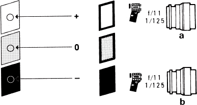
Figure 12-5 Reflected meter readings A reflected light meter reading is correct only when taken off a subject area of average brightness reflecting about 18% of the light. Exposure must be increased for brighter subjects, decreased for darker ones (left). An incident meter reading gives the same exposure ( f/11 and 1/125), whether held in front of a white, grey, or black subject (right).
Figure 12-6 The zone system exposure principle Lens settings, based on a reflected meter reading of 18% gray, record this middle gray tone as zone 5. A reflected meter pointed at white records white also as a zone 5 middle gray and does the same for black (b). For correct exposure, only middle gray should be recorded as zone 5. To place white and black at the ends of the curve (for example, as zones 1 and 9), you must make adjustments in the reflected meter readings (a).
Reflectance Values of Different Colors
Most subjects that we photograph are not in different shades of gray tones, but in different shades of colors which reflect different amounts of light. The color chart in the color section of the Manual should help in determining what shades and colors need corrections and how much. A reflected meter reading of the colors in column 0 should be correct without any adjustment. A reading made of colors in column +1 need a one-stop exposure increase, those in column +2 a 2-stop increase. A reading made of the darker colors in column –1 requires a 1-stop decrease.
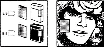
Figure 12-7 Use of a graycard Instead of measuring the light reflected off the subject, you can measure the light reflected off the graycard. The reading is then the same whether the card is held in front of the white or the black lighter (left). A graycard reading should provide the correct exposure in a portrait regardless of the color of the skin (right).
SHADED AND LIGHTED AREAS
Many subjects that we photograph have areas that are brightly lit and other areas that are in the shade. Whether working with an incident, reflected, or built-in exposure meter, the photographer must decide whether to expose for the lighted areas or the shaded areas or somewhere in between. There is no metering system in the world that will do this for us automatically. The logical thought is perhaps to set the lens somewhere between the two readings, a solution that often works with negative but not with transparency films.
Exposing Negatives Versus Transparencies
Negative and transparency films need different exposures with subjects or scenes that have important details in shaded and lighted areas. To produce high-quality prints, black and white and color negatives must have adequate details in the primary shadow areas. Negative films (black and white or color) therefore must be exposed for good shadow density. You want to base the lens settings on the meter reading of the important shadow areas or set them to a value between the shadow and highlight readings.
Transparencies almost invariably must be exposed for the lighted areas; otherwise, the lighted areas look overexposed, become washed out, and lose color saturation. You really cannot worry about shadow details in transparencies except to try to avoid large shaded areas in the composition unless used for effect. Point the metering area at a lighted part of the scene or subject, or take an incident reading in the lighted part. Whether you take a shadow reading for negatives or a highlight reading for transparencies, you must point a reflected or built-in meter at an 18% reflectance area or else make the adjustments mentioned earlier (see Figure 12-8).

Figure 12-8 Exposing for negatives and transparencies 1. With transparency materials, the meter reading should be based on lighted areas marked P, for negative materials on shaded areas marked N. 2. Reflected light meter readings must be based on the main subject without being affected by light (right) or dark backgrounds (left).
Another metering approach that can be recommended and saves time, especially if you take pictures of the same subject on transparency and negative film, is as follows. Take the meter reading of the lighted area as suggested for transparency film, and take the transparency. Decrease the EV value one number (assuming both films have the same ISO value), and take the picture on the negative material. The increase in exposure gives the additional needed shadow details.
If you plan to make color prints from a color transparency, you may want to take a special transparency at an aperture 1 stop larger for more shadow details.
Handheld spot meters, and metering systems in the camera, make it easy to see whether the metering cell measures a lighted or a shaded area. They have a definite advantage for this purpose.
USING VARIOUS METERING SYSTEMS
Reflected light readings can be taken with a regular handheld exposure meter, a handheld spot meter, or a metering system built into the camera or built into a viewfinder. Handheld exposure meters, the standard for many years, have become rather sophisticated, offering various metering modes and digital readouts. They still serve a good purpose for amateur and professional photographers. Handheld spot meters, showing the exact measuring area in a viewfinder, are great tools in the hands of photographers who have a thorough knowledge of exposure and metering.
Although separate handheld meters are good tools, a good metering system built into a modern camera can provide more accurate readings in a much simpler and faster fashion and should therefore be seriously considered for serious amateur and professional photography.
Metering Systems Built into Cameras
Metering systems built into cameras have one thing in common: They all measure the light reflected off the subject or scene, so you must consider the points that have been said about reflected meter readings. Otherwise, builtin meters are of different designs, offering different metering modes, different ways of showing and transferring the metering information, and different degrees of automation. The requirement that is essential for me, and I feel essential for serious photography, is a system in which the measuring area is clearly indicated in the viewfinder. I do not use matrix metering, where the system measures different parts of a scene with individual metering cells; a computer in the camera then compares the various readings and selects an average. Such a meter produces good exposures in snapshooting and is therefore the system used in point-and-shoot cameras. I do not suggest it for serious work because the measuring area is unknown or difficult to determine. My suggested metering mode can be either center area metering or center-weighted metering or a spot meter; with both systems, I know what I am metering. With such a system your exposures with any subject in any lighting situation can be perfect, usually without bracketing.
Average Metering
Average metering means measuring the entire, or almost the entire, image area equally from side to side and top to bottom. It can be a good choice for fast shooting in compositions without large dark or bright areas such as a white sky. The H camera offers the averaging metering option, with the meter reading based on a 45 × 37mm center area, or about 70% of the total image area.
Center-Weighted Metering
The built-in meter measures more or less the entire area seen in the viewfinder but not equally. The meter reading is based mainly on the subject brightness in the center portion of the composition. Because the main subjects are usually in the center, such a metering system works well in most cases. Compared with average metering, it reduces the danger of measuring unimportant dark or light background areas. In the center-weighted mode in the H camera, most of the reading is based on a center area about 23 × 20mm in size, or approximately 20% of the total image area. The Hasselblad PME 51 meter prism (discontinued) has a center-weighted system, with approximately 50% of the exposure reading based on the light reflected from a center top area (see Figure 12-11).
Center Area Metering
Center area metering is very similar to center-weighted metering except that the meter measures only the center area. Center metering is the method used in the XPan camera. It is also one of the options on the PME meter prism finders, where most of the light is measured within a 40mm center area. Center area metering is also the measuring mode in the 202 and 203 camera models, with approximately 75% of the light measured in the indicated center area. Because a center area metering system measures the most important (center) area of the composition, the readings are in most cases accurate enough to allow use of the 200 cameras and the XPan cameras in the automatic mode, with excellent results even on transparency films.
Spot Meters
A spot meter measures a small center area outlined on the focusing screen. A well-designed spot meter measures only the light within the small outlined area and is virtually unaffected by any light from outside areas, no matter how bright it might be. A spot meter offers a very precise method for metering small, specific areas or various areas within the composition to determine the brightness difference, such as between shaded and lighted areas. The spot meter in the 205 camera measures about 1% of the total image area; about 2% is measured by the 7.5mm circle in the H camera. PME finders set for spot metering measure a 12mm center area.
The measuring angle of a built-in spot meter depends on the focal length of the lens on the camera. On the 205 camera, it is 4.5 degrees with the 80mm lens, and 3 degrees with the 110mm lens, and it becomes a 1-degree spot meter when the reading is made through a 350mm lens. The measuring angle of the PME spot meter is 12 degrees with the 80mm lens.
Exposure in Electronic Imaging
The evaluation of the tonal range and exposure in electronic imaging is discussed in Chapter 2, Digital Imaging with Hasselblad.
THE HASSELBLAD METERING SYSTEMS
The metering system in the H camera can be set for average, center-weighted, or spot metering, with many different light-measuring approaches and programmable functions that can match the metering approach to your photography. Details are in Chapter 4.
The 205 camera models have built into the camera body a spot meter that can be operated in various modes, including the Differential and Zone modes, which provide a wonderful way of locking an exposure value. They are used in Aperture Priority or Manual mode.
The 203 and 202 models have center metering that can be operated in the Aperture Priority or Manual mode and in various fashions, including Differential.
The PME viewfinders can be set for incident metering and for reflected metering either in center metering mode or as a spot meter (see Figures 12-9 and 12-10). The viewfinders can be attached to any 500,200, or 2000 camera model as well as the focusing screen adapter on the Superwide cameras, the FlexBody, and the ArcBody, providing TTL metering in all cases. The readings in the finder must be transferred manually to the lenses.
The center area metering system in the XPan camera measures approximately one-third of the total image area and can be operated manually or automatically (see Figure 12-12).
The Advantages of a Built-In Metering System
A built-in metering system offers a number of advantages:
• A metering system in the camera or viewfinder eliminates the need to carry and worry about a separate meter.
• Determining and making the lens settings is much faster than pointing a hand-held meter at the subject, reading the figures on the meter, and transferring them to the camera or lens. With all Hasselblad built-in metering systems, you can take the meter reading while you compose. With the 200 cameras, you only need to set the aperture; the shutter speed sets itself automatically and changes automatically. With the H camera set to P or Pv, you need not make any lens settings manually. Just point and shoot, or for more control, you can preset either the aperture or the shutter speed. With the PME finders, you just read the EV value and set the figure on the lens.

Figure 12-9 Metering patterns in PME meter prism finders In addition to incident metering, the PME 90 and PME 45 meter prism finders offer the option of a spot meter measuring a 12mm center area within the four black lines (left) or center area metering where most of the light is measured within a 40mm center area (right).
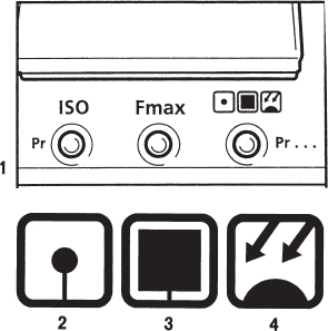
Figure 12-10 Selecting the metering mode On the PME 90 and PME 45 meter prism finders, you set the desired metering mode by pressing the metering mode button marked Pr (1) and then pressing the up or down adjustment button until the desired mode symbol appears on the viewfinder display. The metering mode symbols are spot meter (2), center area metering (3), and incident metering (4). The ISO button is for setting the film sensitivity. The Fmax button is for setting the maximum aperture of the lens on the camera.

Figure 12-11 Metering area on PME 51 and earlier PME finders In the PME 51 center-weighted meter prism finder, approximately 50% of the light is measured in a top center area with all focal length lenses. This measuring area for the PME 51 is indicated by a dotted line on both diagrams. On the old PME prism finder, the metering area depended on the focal length of the lens. The solid line on the left shows the metering area for lenses up to 110 mm, and the solid line on the right for lenses 110 mm to 350 mm. The small area indicated by the broken line on the right is for the 500mm Tele-Apotessar.
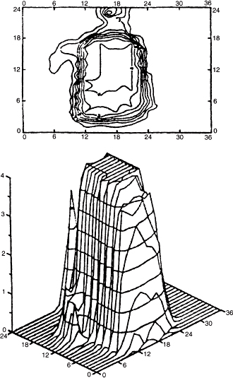
Figure 12-12 Metering pattern of XPan camera The classic center area metering pattern of the XPan camera is concentrated within about one-third of the total area, weighted slightly toward the top. It gives good meter readings whether the camera is held horizontally or vertically.
• The possibility of making mistakes is reduced because few or no values have to be transferred and few or no manual settings have to be made.
• With the measured area known or visible on the focusing screen when you compose the image, you always know what area is measured by the meter, or you can easily select the area or areas that you want to measure.
• Because the light is measured through the lens (TTL metering), the focusing screen always shows the correct measuring area, no matter which lens is on the camera. When you change lenses, the measuring area adjusts automatically to the area coverage of the new lens. This is especially valuable when you are working with longer focal length lenses or photographing distant subjects that may not permit a close-up reading with a separate meter.
• All the information you need to know about exposure and lens settings is visible in the viewfinder while you are composing and evaluating the image. You need not remove your eye from the finder to make changes, and warning signals may appear if a problem exists.
• The light is measured through accessories placed in front of the lens, such as filters, or accessories that are between the lens and camera, such as extension tubes, bellows, and teleconverters. The reading in the viewfinder or settings on the camera are correct without the need for considering filter or exposure factors.
• In the 200 model cameras and the H camera, lenses and film magazines are or can be electronically coupled to the camera body, offering the ultimate solution for speed, convenience, and accuracy.
The Advantages of Spot Metering
In addition to all the advantages of built-in metering systems mentioned in the preceding paragraph, a spot meter in the camera offers a few other benefits:
• The small spot metering area can be aimed at very specific subject areas, where you know exactly the color and brightness and you know whether the indicated lens settings are correct or whether adjustments need to be made and, if so, how much, based on the color chart in this book. The reading is not affected by light coming from outside areas. Your lens settings can be extremely precise, usually eliminating the need for bracketing.
• The small spot metering area makes it easy to measure various areas within the subject or scene to see the differences between lighted and shaded areas and between the main subject and the background so that you know the contrast range. It also makes it easy to determine the difference between the area lit by a main light and the area lit by a fill light so that you know the lighting ratio, allowing you to make changes in the lighting before you take the pictures.
• The spot meter readings between light and dark areas can be used to determine the proper developing time that produces the desired contrast on black and white negatives.
• The 205 camera can give you the spot meter readings in zone values, and the camera can be used with a CC magazine that has a control for automatic contrast adjustment based on Ansel Adams's zone theory.
Metering Procedure with Built-In Meters
Whether the metering system is built into the camera or the viewfinder, the basic metering approach is the same. A good, fast approach for determining aperture and shutter speed with a center-weighted or spot metering system is as follows:
1. Prepare the camera for the ISO rating of the film and the proper meter operation. For example, preset the lens aperture (on XPan and 200 cameras), set 200 camera models to either Differential or Zone metering, or set the H camera for aperture or shutter speed priority so that exposure is locked (as discussed in the H camera operations in Chapter 4). Set meter prism finders for the maximum aperture of the lens. Close the lens aperture manually if required (on shutter lenses without Databus connections used on 200 camera models).
2. Determine the camera position that provides the desired composition.
3. Evaluate the subject or scene to determine whether it includes areas of average brightness with about 18% reflectance and whether these areas are in sunlight (for transparency film) or in an important shaded area (for negative emulsions).
4. If such areas exist, point the center or spot meter area at that part of the composition, and then do the following:
a. Read the EV value on the meter prism finder and set the value on the lens.
b. Press the AE lock in the side of 200 cameras, thereby turning on the camera and also setting and locking the shutter speed.
c. Make certain that the H camera settings lock the metered value.
5. Move the camera for the desired composition and take the picture.
This approach is easy and fast even with a spot meter because it eliminates the need for making exposure compensations.
A compensation must be made if there are no areas of average brightness. For example, in a snow-covered landscape I take a reading of the snow and then increase the exposure by two EV values.
I suggest that you always check the set aperture and shutter speed values before pressing the release.
THE 205 ZONE MODE IN COLOR PHOTOGRAPHY
Although the zone system applies only to black and white photography, the zone mode in the 205 camera can be helpful when you are working with color film. Instead of thinking about exposure adjustments in EV values, you can give a zone value to any color. Any color that reflects 18% of the light or 18% gray, such as a green field, is zone 5. Any shade or color that is one stop darker, such as most evergreen trees, becomes zone 4; a shade or color that is brighter goes into a higher zone value, with snow placed in zone 7. The zone values for various colors are indicated at the bottom of the color chart in the color section of this manual.
Zone values are easier to remember than compensations in EV values, especially because there is no need to remember whether exposure must be increased or decreased.
BRACKETING
By using any of the Hasseblad metering systems described earlier, you should have very satisfactory exposure of all your negatives or slides. Bracketing, which means taking images of the same subject or scene at two or more different exposure settings, should not be necessary. Bracketing, however, is still recommended whenever you have any doubts about the result, when you cannot find subject areas of a known reflectance value for metering, and when you photograph subjects that have a high contrast range. Sometimes you may also want to bracket for the purpose of producing the most effective image, not necessarily the best exposure. Sometimes the two are not the same. You may sometimes prefer a darker image because it is more dramatic and has more color saturation. An early morning picture or a picture taken in the fog may be more beautiful when colors are more on the pastel side, creating a high-key effect.
For critical work on transparency film, such as in beauty or product photography, you probably want to bracket in ⅓ or ½ f stop increments. For most other work, bracketing in full f stops makes more sense even with the modern transparency films. Manual bracketing is a good approach in most cases.
On the H and XPan cameras, and on most 200 models equipped with a motor winder, you can bracket automatically, a feature that is wonderful in situations when you must work fast. A sequence of three bracketed shots can be made in almost the same time as a single picture and without moving the camera from the eye.
EXPOSURE WITH FILTERS AND CLOSE-UP ACCESSORIES
When accessories are placed in front of the lens or between the lens and the film, such as the accessories for close-up photography, the light reaching the image plane is reduced. You must compensate for the loss if the meter reading is made with a handheld exposure meter. Check the required increase in the instructions for the accessory or, in other sections, of this manual for tele-converters and close-up accessories. The lens settings shown on built-in meters or meter prism finders are correct because the light is also measured through the accessory. When using teleconverters or extension tubes without Databus connections on 200 cameras, you must manually close down the aperture when taking the meter reading, just as you do with lenses without the electronic connection.
On meter prism finders, set MAX at the maximum aperture engraved on the lens, as you normally do. A meter reading with a meter prism finder attached to the focusing screen adapter on the FlexBody or ArcBody should be taken before shifting or tilting, and exposure tests are recommended.
EXPOSURE WITH VARIOUS FOCUSING SCREENS
The PME 90, the PME 45, and the earlier models PME 51, PME 5, and PME 3 are adjusted to provide the correct exposure with any type of Acute Matte screen, at least when used in center area metering. The spot meter reading is affected by the bright center area of the microprism and/or split-image rangefinder area. These screens should therefore be used only in the center area metering mode. If you plan on using the spot meter mode of the PME 90 or PME 45, use an Acute Matte screen without microprism or split-image rangefinder area.
The meter prism finders mentioned earlier do not give correct exposure in combination with the various types of earlier groundglass screens. Changing the screen is highly recommended.
Earlier meter prism viewfinders not mentioned here were made for the old focusing screens and need a one-stop increase in exposure when used with the Acute Matte types. Exposure tests should also be made when these viewfinders are used with special lenses and teleconverters.
THE PME 90 AND PME 45 METER PRISM VIEWFINDERS
The metering areas, the metering options, and the operation of the metering system are identical in both finders. The two finders (see Figures 12-13 and 12-14) differ in the following few points.
The metering system in the PME 90 is operated from a lithium CR123A, and the PME 45 from a lithium CR2 (see Figure 12-16). The PME 45 has a diopter correction from –2 to +1, with the possibility of using accessory eyepieces with corrections from –4.5 to +3.5. The PME 90 has a correction from –2 to +0.5. Accessory eyepieces from –4 to +3 diopters are available for the PME 90 finders.
The PME 90 has an illumination window for the viewfinder display, and the PME 45 does not. Whenever the PME 45 is turned on, the display is illuminated via LEDs powered by the battery. The magnification is 2× on the PME 90 and 2.5× on the PME 45. The PME 45 can be used with the instant film magazine attached to the camera, and the PME 90 cannot.
Basic Meter Prism Operation
As with any exposure meter, the ISO film sensitivity must be set on all meter prism finders. Because the meter reading is made with the lens aperture fully open, as it normally is, all meter prism viewfinders must also be set for the maximum aperture of the lens on the camera and must be changed when you switch to a lens having a larger or smaller maximum aperture. As a precaution, I might suggest that you make certain that the lens is not manually closed down when the meter reading is taken. If you want to take a meter reading with the lens manually closed down, you must set the maximum aperture value for the preset aperture.

Figure 12-13 The PME 90 operating controls.
1. Locking clip
2. Indication mark
3. Eyepiece diopter adjustment
4. Removable rubber eyecup
5. Eyepiece diopter lock
6. Battery compartment cover
7. ISO setting button
8. MAX aperture setting button
9. Metering mode symbols
10. Metering mode selector
11. Upper and lower adjustment buttons
12. Metering button
13. Display illumination button
14. Display illumination symbol
15. Display illumination window
16. Incident metering dome
17. Accessory shoe
18. Viewfinder type emblem
19. Cover for service use
20. Magazine catch operating slide
21. Viewfinder retaining plate
22. Prism
23. Protective cover
On the PME 90 and PME 45, you set the ISO value by pressing the ISO button and then using the adjustment controls to set the ISO value. You use the same approach for setting the maximum aperture after pressing the Fmax button (see Figure 12-15). The aperture setting is not necessary for incident meter readings because the light is not measured through the lens.
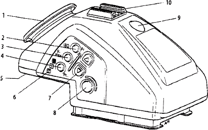
Figure 12-14 Operating controls on the PME 45.
1. Rubber eyecup
2. ISO selector knob
3. MAX aperture selector
4. Metering mode selector
5. Eyepiece diopter adjustment lock
6. Metering mode symbols
7. Up and down adjustment buttons
8. Metering button
9. Incident light dome
10. Accessory shoe
On the PME 90, the display is illuminated from a window on top of the viewfinder. Don't cover it up with your hand. You can illuminate it in low-light levels by pressing the illumination button. The PME 45 display is illuminated permanently from the inside.
Operating the PME 90 and PME 45 Meters
When the meter is turned on, the display shows the maximum aperture and the film sensitivity set on the finder. After 1.5 seconds, the display changes to show the meter reading, which can be in EV values or as aperture or shutter speed priority. In aperture priority, the display indicates the correct shutter speed for the set aperture; in shutter priority, it shows the necessary aperture for the preset shutter speed. Selecting EV values is usually the most practical, fastest, and least mistake-prone solution with Hasselblad shutter lenses.
The PME Programming Functions The programming functions work in all metering modes: spot meter, center metering, and incident metering. You obtain the programming mode by simultaneously pressing the ISO and meter mode selection buttons. These two buttons have a small Pr engraving next to them. You obtain the different programming possibilities (from Pr 1 to Pr 7) by pressing the metering mode button repeatedly.
With Pr 1 turned on, the meter display shows EV values. If you prefer either aperture or shutter speed priority, turn off Pr 1 and turn on Pr 2. You change from aperture to shutter speed priority by pressing either adjustment button.

Figure 12-15 Viewfinder display for various operating modes The set ISO value and the MAX lens aperture (D 1) appear on the screen when the meter is turned on with the metering button. After 1.5 seconds, the display changes (D 2). The set ISO value is shown after the ISO button is pressed (D 3). The set maximum aperture can be seen after pressing the Fmax button (D 4). The metering mode symbols (D 5) are (left to right): spot meter, center metering, and incident metering mode. In the Pr 1 mode, the meter shows EV values (D 6). In Pr 2, the meter is set for either aperture priority or shutter speed priority instead of EV values (D 7). In Pr 3, a reference value can be programmed into the meter. It is turned off (D 8) and turned on with a +1 and –1 value programmed into the finder (D 9). The metering duration is programmed in Pr 4 and is set to 16 seconds in A permanently (D 10). An exposure correction from +2 to –2 can be programmed into the meter in Pr 5 (D 11).
With Pr 6 turned on, the set ISO and maximum aperture values appear on the display for 1.5 seconds before the meter reading comes on (D 12). A sound warning can be added to the reference mode in Pr 7 (D 13). Display with center area metering and aperture priority (aperture figure solid) is shown (D 14). A stored value is indicated by an arrowhead pointing toward the stored value, in this case the aperture (D 17). All values programmed into the PME finders remain memorized in the finder until they are changed. Removing or replacing the battery does not affect the settings.

Figure 12-16 Inserting the battery in PME 90 and PME 45 You insert the 3V lithium battery as shown, after opening the battery compartment cover. A battery symbol appears on the viewfinder display when the battery needs to be replaced.
The length of time that the meter stays on can be programmed from 5 seconds to 60 seconds in programming function Pr 4. Pressing the adjustment buttons changes the time. For most photography, the standard 16 seconds is a good compromise.
Programming function Pr 5 allows programming an exposure correction from –2 to +2 f stops into the meter prism. Pressing the up adjustment button increases the correction value, and pressing the down control decreases it.
By pressing either adjustment button, you can have the Pr 6 programming function turned on or off. In the On position, the ISO and the maximum aperture set on the meter appear on the display for 1.5 seconds every time the meter is turned on. I feel that this is a good reminder for most photographers. In the Off setting, the metered value appears immediately.
The reference mode allows you to program specific limits into the meter so that a warning appears on the display when the reading exceeds the programmed limits, such as the brightness range. The reference mode is shown on the finder display by programming Pr 3, which is turned on or off with the down adjustment button. You set the reference value by pressing the up adjustment button. You can add an audible warning by turning on Pr 7.
The PME 51 Meter Prism Finder
The PME 51 meter prism viewfinder (now replaced by the PME 45) combines convenient 45-degree viewing with TTL (through the lens) metering. It has a center-weighted metering mode, with approximately 50% of the light measured in the top center area.
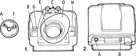
Figure 12-17 The PME 51 meter prism finder 1. (A) Film sensitivity selector; (B) film sensitivity scale; (C) flash and accessory shoe; (D) removable, rotatable eyecup; (F) aperture setting lever; (G) aperture indication window; (H) green battery check signal. 2. (A) Operating button; (B) battery cover. Earlier versions of the finder also had a retaining ring (F) for correction lenses. On the latest versions, the entire eyepiece is changed.
The exposure reading is shown in EV values below the image area. If two figures light up, the value is between the two; for example, it is EV 13.5 if values 13 and 14 are lit. The meter is powered by a 6V battery, PX28 or similar. A green signal in the right viewfinder window lights up when the meter is turned on, also indicating that the battery is in good condition. You set the meter to the film sensitivity and the MAX aperture by turning the two selector dials until the proper figure appears between the lines in the window. To obtain a meter reading, press the operating button for one second and the LEDs at the bottom of the finder will light up, showing the EV value (see Figure 12-17).
DISCONTINUED ITEMS FOR EXPOSURE METERING
Original Meter Prism Finder
Meter indications were via a moving needle. This finder cannot be recommended for today's photography.
PME/VFC-6 Prism Finder
This 45-degree finder was similar to the later PME versions but adjusted for the old focusing screens.
Exposure Meter Knob
The exposure meter knob can be attached to the original 500 camera models in place of the regular winding knob or crank. It has a built-in selenium meter that does not require a battery but is limited in low-light measurement. The meter knob can be used as a reflected or an incident exposure meter on or off the camera.
Automatic Aperture Control Lenses
The Planar 80mm and 100mm and the Sonnar 150mm and 250mm lenses used to be available with an attached servomotor, which opened and closed the diaphragm automatically and therefore provided fully automatic exposure control. Because only a few are in use, instruction is not included here. If help is needed, call the Hasselblad agent.