
15
Operating the FlexBody and ArcBody
For years, the Hasselblad camera system was considered perfect for any type of photography except for applications that required swing and/or tilt control. To eliminate these limitations Hasselblad added the FlexBody, the ArcBody, and the PC Mutar to the V system line. The FlexBody and the ArcBody were not introduced as substitutes for studio cameras; instead, the aim was to give the Hasselblad location photographer the possibility of swing and tilt control on inexpensive rollfilm without the need to carry a large studio camera with an assortment of large-format lenses.
The FlexBody allowed creation of pictures with a sharpness range way beyond the depth-of-field capability of the lens. The ArcBody allowed architectural photography with view camera capability. Unfortunately, not very many photographers showed an interest in using Hasselblad cameras for these special applications, perhaps because the computer age had reduced the need for such controls. Slanted verticals, for example, can be corrected in the computer. The limited demand made it necessary for Hasselblad to discontinue the FlexBody and the ArcBody.
CAMERA DESIGN
The FlexBody and the ArcBody are camera bodies with a flexible bellows that allows the photographer to shift and tilt the image plane. In both cameras the image is recorded in Hasselblad V system film magazines or certain V system electronic backs. On the FlexBody the image is recorded with Hasselblad V system shutter lenses. The front of the ArcBody is designed for the use of Rodenstock lenses specially designed for the ArcBody.
On both cameras, the image is evaluated on the focusing screen adapter specifically made for these cameras and included in the camera package. Figure 15-1 shows the main FlexBody operating controls, and Figure 15-2 shows those of the ArcBody.

Figure 15-1 The important FlexBody operating controls.
1. Rear standard
2. Winding crank lock
3. Tilt scale
4. Winding crank
5. Tilt index
6. Front standard
7. Drive shaft
8. Lens release lever
9. Close-up extension wheel
10. Lens marking
11. Tilt control lock
12. Tilt control
13. Shutter cocking knob
14. Cable release socket
15. Shift control knob
16. Locking knob for close-up extension
17. Quick coupling plate with 1/4-inch and 3/8-inch tripod thread (18, 19)
20. Magazine support
21. Rear frame
22. Magazine hooks
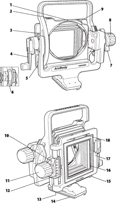
Figure 15-2 The ArcBody operating controls.
1. Lens alignment index
2. Spirit level
3. Lock for film winding crank
4. Film winding crank
5. Spirit level
6. Tilt scale
7. Lock for tilt control
8. Tilt control
9. Lens release catch
10. Lock for shift control
11. Shift control
12. Shift scale
13. Spirit level
14. Quick coupling plate
15. Magazine supports
16. Stray light mask
17. Rear standard
18. Magazine hooks
USING THE TILT CONTROL
On an “ordinary” camera, the sharpness range is determined completely by the depth of field of the lens at the set aperture. When you are photographing a flat plane from an oblique angle—as in a tabletop setting, a food illustration, or a landscape photograph of a flat area such as a water surface—or a flat field, you can control the sharpness range independently from the depth of field by tilting the image plane. You can have almost unlimited sharpness, even at large lens apertures that allow short shutter speeds (see Figure 15-3).
This tilt control principle, which applies to any camera, in any format, and with any lens, is known to large-format photographers under the name Scheimpflug (the name of the photographer who came up with the principle). It is based on the following:“When photographing a flat plane from an oblique angle, you have the maximum possible sharpness range when a line extended from the lens plane and a line extended from the image plane meet at a common point on a line extended from the subject plane”(see Figure 15-4).
Although the Scheimpflug principle could be applied to predetermine or calculate the amount of tilt, you will probably find that you can more easily determine the necessary degree of tilt and the correct focus setting on the FlexBody or ArcBody by evaluating the image on the focusing screen. Start perhaps by focusing the lens at a point approximately one third beyond the closest and two thirds in front of the farthest subject distance, at 14 feet (4.3m) when the closest subject is 6 feet (1.9m) and the farthest 30 feet (9.1m). Tilt the image plane in one direction, and check whether the sharpness range increases. If it does not, tilt the plane in the other direction. Check the sharpness at the top and bottom and see whether both become critically sharp at some point. If they do not, change the focus setting on the lens. You will quickly find a point where you have sharpness over the entire plane. Lock the tilt control.

Figure 15-3 Depth of field and sharpness range The lens aperture produces a specific amount of depth of field at a certain aperture, f/8 in the example (top). You can extend the range of sharpness at the same aperture by tilting the image plane in relation to the lens plane (bottom).
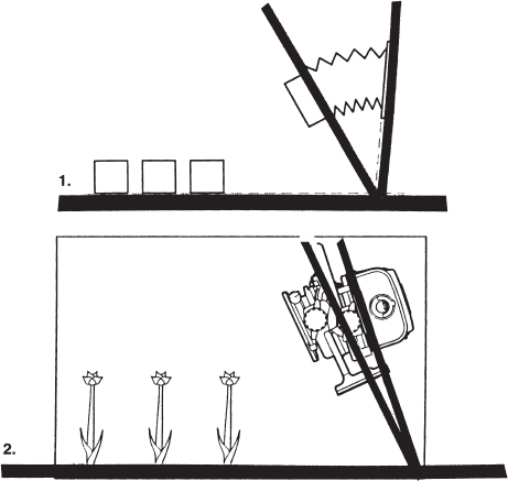
Figure 15-4 Maximum sharpness range The maximum sharpness range on the FlexBody (1) or ArcBody (2) is obtained when lines extended from the lens plane and image plane meet at a common point on a line extended from the subject plane.
Limitations of Sharpness Controls
With the tilt control you can accomplish sharpness over the entire area even with the lens aperture wide open, but only if you have a flat subject plane, such as the surface of a table or a flat field in the landscape. If there are any three-dimensional subjects on the table—a vase with flowers, a bottle of wine—or a building or tree in a landscape, the various subjects are no longer on a flat plane. We have at least two different image planes; one is the flat surface, the other a plane going from the surface to the top of the subject (see Figure 15-5). You can adjust the tilt for either, but not for both. The difference must be corrected with the lens aperture and its resulting depth of field.
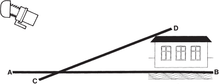
Figure 15-5 Sharpness in different subject planes The image plane can be tilted for sharpness in one subject plane only, either the plane A to B or the plane C to D. The depth-offield control must be used to achieve sharpness in both planes.
The tilt control also allows you to do the opposite—to limit the sharpness to one particular plane, one specific product, a specific person, or even part of the person. This flexibility is especially helpful when the different subjects are at the same distance and the depth-of-field control does not work. Be careful when using the tilt control for limiting the sharpness range because it is a special effect that can easily look artificial and attract unnecessary attention. When you tilt the image plane (not the lens plane), as done on the FlexBody and the ArcBody, the image plane remains in the center of the optical axis. You can tilt as much as necessary without the need for special lenses with a larger covering power. That explains why V system Hasselblad lenses can be used on the FlexBody without any limitations.
The tilt control in both cameras works only up and down. If you need to tilt along the horizontal plane, tilt the entire camera sideways.
THE SHIFT CONTROL
On the FlexBody and the ArcBody, the image plane can also be shifted— moved up or down while remaining parallel to the lens plane. The main applications are in product and architectural photography. Instead of tilting the camera upward to cover a building to the top, resulting in slanted verticals, you can shift the image plane downward (see Figure 15-7). By doing so you can keep the image plane parallel to the subject plane—the wall of the building—as you do on the PC Mutar by shifting the lens plane. By turning either camera sideways, you can accomplish the same results in the horizontal plane (see Figure 15-8).
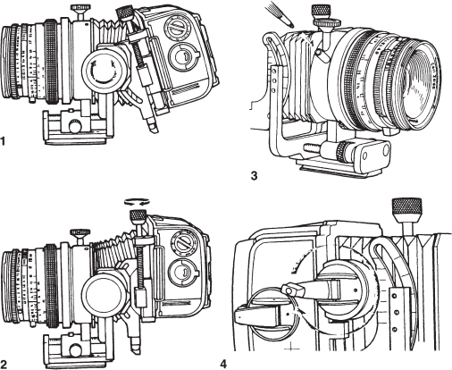
Figure 15-6 Operating the FlexBody controls 1. You tilt the image plane by rotating the large tilt knob. 2. You move the image plane up or down by turning the shift control knob on top. 3. You extend the front for close-up photography by turning the knob below the lens. 4. You advance the film by turning the winding crank. The ArcBody has the same controls, but they are in somewhat different locations and operate in a slightly different fashion.
Table 15-1 Maximum Shift in Millimeters on the FlexBody with Various Lenses
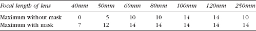
Limitations of the Shift Control
When using the shift control you are moving the image area out of the optical axis and out of the 78mm covering power circle of the Hasselblad V system lenses. Soon, two corners of the image darken, or even vignette, and lose image sharpness. Shifting with the Hasselblad lenses on the FlexBody is therefore limited, as indicated on the first line in Table 15-1 for various lenses. You can extend the shift capability to the values shown on the bottom line of the table if you are satisfied in covering the subject in a horizontal 6 × 4.5 format. A mask for this format comes with the FlexBody.

Figure 15-7 Use of the shift control A tilted camera results in slanted lines (top). Instead of tilting the camera, you can shift the image plane downward until the top of the building is included in the composition, keeping the image plane parallel to the building (bottom).
Considering these limitations, the FlexBody with its tilt capability serves its purpose best for increasing the sharpness range. For architectural and similar work that requires shift control, consider the ArcBody (or the PC Mutar lens discussed in Chapter 14). This camera was introduced to eliminate the limitations of the covering power of Hasselblad lenses. The Roden-stock lenses that must be used on this camera have a much larger covering power, so you can shift 28mm with all three lenses of 35mm, 45mm, and 75mm focal length without losing image quality.
CLOSE-UP PHOTOGRAPHY WITH THE FLEXBODY
The front frame on the FlexBody with the lens can be moved forward as much as 22mm for close-up photography. Moved to 22mm, it produces the same results as a 22mm extension tube would with the same lens on other Hasselblad V system cameras. I suggest using this close-up extension only for close-up photography. For photography at normal distances, move the front frame all the way to the rear, and focus the lens with its focusing ring.

Figure 15-8 Use of the shift control horizontally Instead of turning the camera to record a subject that cannot be photographed from the center (top), you can shift the image plane (bottom) to include the desired subject area.
VIEWING, FOCUSING, AND EVALUATING THE IMAGE
On both cameras, the image is evaluated on the focusing screen adapter, in combination with either any Hasselblad V system camera viewfinder or the special RMfx Reflex finder, which shows the 3.3× magnified image right side up. The image on the Acute Matte focusing screen is bright to the corners, at least when the tilt and shift controls are in the 0 positions. When you tilt or shift, the image on the top or bottom of the screen darkens because your eye is no longer aligned in the optical axis. The darkening does not happen on the film.
The Fresnel slides supplied with both cameras solve this problem beautifully (see Figures 15-9 and 15-10). The FlexBody slide marked “10” is used for tilt angles from 5 degrees to about 15 degrees, and the slide marked “20” is used for greater angles. The three slides that come with the ArcBody are marked “Small” for corrections up to 5mm, “Medium” for corrections 5 to 15mm, and “Large” for corrections more than 15mm, all with 35mm and 45mm lenses. The slides marked 10 and 20 are used with the 75mm lens.
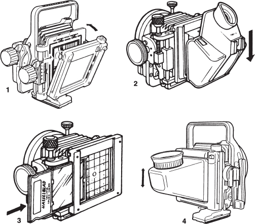
Figure 15-9 The focusing screen adapter and correction slides 1. You attach the focusing screen adapter by placing it on the lower support hooks and then pushing it toward the top of the camera while pressing the release lock. Press the release lock to remove it. 2. Viewfinders are inserted from the top. 3. The correction slides are inserted either from the left or right but always with the text toward the rear. 4. The RMfx viewfinder attached to the focusing screen adapter gives an upright image.
TAKING A PICTURE WITH THE FLEXBODY AND ARCBODY
After the image plane is adjusted, the lens focused, and the aperture and shutter speeds set on the lens, remove the focusing screen adapter, and attach the film magazine but do not remove the darkslide (see Figure 15-11). Proceed as follows:

Figure 15-10 Purpose of correction slides 1. When the image plane is parallel and centered with the lens plane, all the light goes toward the eye. 2. When the image plane is shifted without a correction slide, the light rays are not in line with the viewing axis, darkening one side of the focusing screen. 3. The correction slides redirect the light rays to the center of the eye for equal brightness over the entire screen area. 4, 5. The same happens when the image plane is tilted.
1. Attach the supplied cable release, and press the release halfway. You will hear the lens shutter closing.
2. Remove the darkslide.
3. Press the release completely. The shutter opens and closes to make the exposure.
4. Insert the darkslide before you do anything else. Make certain you do not cock the shutter before the darkslide is in the magazine. That would expose the film to light.
5. Recock the shutter.
6. Advance the film using the film winding crank on the FlexBody.

Figure 15-11 Photographing with the FlexBody After the lens settings are made and the film magazine is attached, press the cable release halfway (1) to close the lens shutter. Remove the darkslide (2), and press the release completely (3) to make the picture. Then insert the darkslide (4), recock the shutter (5), and advance the film (6).
The ArcBody operation is identical, but you must also operate the open/close lever for the shutter on the lens. You must also use the central neutral density filter with the 35mm and 45mm lenses to achieve even brightness over the entire image area (discussed in Chapter 14).