22
Projecting Medium-Format and XPan Transparencies
PROJECTING XPAN TRANSPARENCIES
Transparencies in the standard 35mm format, either cardboard- or glass-mounted, can be projected in standard 35mm projectors. The 24 × 65mm panoramic transparencies require a 6 × 7cm slide projector and 6 × 7cm slide mount, with the panoramic image area masked off with silver tape.
The 2¼-inch projectors, such as the Hasselblad PCP 80, can be used only for slide sizes up to 55mm, which is 9mm too short for the long side of the XPan panoramic images. To project these images in a 2¼-inch (6 × 6cm) slide projector like the PCP 80, you can consider two solutions. You can cut the long side of the panoramic image down to 55mm; this is not a great solution because well-composed panoramic images lose the effectiveness of the panoramic shape. The other solution is to have a duplicate transparency made in a reduced format of 56mm × 21mm.
THE 2¼-INCH SQUARE AND 6 × 4.5CM TRANSPARENCIES
The 2¼-inch (6 × 6cm) square and the rectangular 6 × 4.5cm formats are excellent for projection. Projectors and slide trays are readily available. Because laboratories return 120 or 220 transparency films unmounted, you must mount your own slides. This is actually an advantage because the large transparencies should be glass-mounted to maintain corner-to-corner image sharpness in projection. Medium-format slides are large, and the heat from the projector would cause excessive popping of a cardboard-mounted slide.
Glass mounts protect slides physically but do not prolong their life or prevent color fading. For longest slide life, keep them in a cool, dry, dark place as much as possible. To minimize fading, do not expose slides to the bright projection light longer than necessary; keep them away from direct sunlight and fluorescent lights such as those found in a light box.
Slide Mounts
Glass slide mounts for 2¼-inch square and for 6 × 4.5cm transparencies are available. Both have the same outside dimensions and can therefore be used in the same slide trays and can be intermixed within a presentation. Plastic frames with rounded corners that slide or snap together are the preferred choice for the precise standards of the film gate in the Hasselblad PCP 80 projector.
If a slide does not drop, check the slide mount first, and make certain that the mounts are firmly pressed together. Do not attach paper or tape to the slide mount to identify slides. Instead, write the identification directly on the mount using a pen that writes on glass and plastic. To avoid having slides appear on the screen upside down or sideways reversed, you may want to indicate the proper positioning with a dot in one corner made with a pen directly on the mount. Proper positioning of all slides is ensured when all dots are visible in the same corner when you glance from the back of the tray.
Slide sequences in a professional presentation may require perfect registration from one slide to the one before and the one after. Such slide registration is achieved with pin registration slide mounts. The Hasselblad mounts are no longer made, but other makes should still be available, as should be the necessary tool to punch the registration marks into the film. These slide mounts are not made for the perforations in 70mm films used in the Hasselblad 70 film magazine. Professional multiple-image presentations usually use duplicate transparencies made in a pin-registered rostrum camera.
New glasses are factory cleaned and need nothing more than brushing off possible dust. For cleaning used glasses, use either a glass cleaner or warm water.
Store glass-mounted slides in areas with low humidity because otherwise the film base soaks up the moisture from the air. The heat from the projection lamp causes the moisture to evaporate, and the moisture may become visible on the screen and will cloud the glass. Moisture that has settled between slide and glass should be removed as soon as possible because it will deform the slide and may result in the growth of fungus. Take the slide apart and let it dry out before remounting.
OPERATING THE HASSELBLAD PCP 80 PROJECTOR
The Hasselblad PCP 80 projector (see Figure 22-1) is the most professional medium-format slide projector. It can be used in applications ranging from simple one-projector shows to the most sophisticated multiple-image presentations, using the same dissolve and control equipment used for 35mm projectors. In spite of the superb performance of the PCP 80, the market for slide projectors has been reduced to a point where Hasselblad was forced to discontinue the product. Part of the reason is undoubtedly the much wider use of newer digital presentation methods.
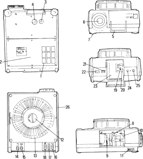
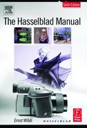
Figure 22-1 Operating controls on the PCP 80.
1. Air filter
2. Baseplate (can be removed to clean the projector)
3. Automatic circuit breaker
4. Voltage selector (does not exist on the U. S. version)
5. Carrying handle
6. Lens holder with projection lens
7. Adjustable feet for leveling
8. Adjustment for matching perspective control to lens
9. Removable condenser lens
10. Perspective control indicator
11. Perspective control adjusting knob
12. Magazine lock
13. Tray
14. Lamp ON switch
15. Lamp OFF switch
16. Forward and reverse slide changing
17. Lens focus control
18. Edit and reset control
19. Transport lock screw
20. AV socket for programmers
21. Power on/off switch
22. Power cable connection
23. Lamp housing door
24. Eight-pin connector for some programmers
25. Six-pin connector for Hasselblad remote control
26. Side cover
Perspective Control
The designation PCP 80 comes from the built-in perspective control and the 80-slide tray capacity. With the built-in perspective control, you can move the image on the screen up and down by simply turning the perspective control knob, which moves the entire optical system from lens to lamp housing.
The weight of the PCP 80, combined with the floating optical system, requires special care in transporting. The PCP 80 has a transport lock for this purpose, which must be removed before you use the machine or operate any controls (see Figure 22-2). The transport locking screw is then inserted into the opening on the knurled knob on the right front foot. After it is inserted, turning the knob operates the perspective control. To ship the projector, reverse the procedure.
Voltage Selection, Projection Lamps, and Illumination System
The PCP 80 projectors sold on the American market are made for 110 volts only and need no adjustment. Other projectors have a voltage selector at the bottom, which must be set to the proper value. The PCP 80 works on 50 or 60 cycles.
The PCP 80 is supplied with two 250W 24V halogen projection lamps held in a common lamp holder. Should lamp 1, which is normally lit, burn out, a microswitch automatically and instantly flips lamp 2 into the projection position. LED lights next to the lamp switch show which lamp is on. If only the green LED is lit, lamp 1 is on. If the yellow LED next to it is also lit, lamp 2 is on, which means that lamp 1 has burned out. In that case, replace lamp 1 as soon as possible. The lamp is an EHJ type (DIN 49820 base 6,35–15) that provides a screen brightness that is completely satisfactory for screen sizes up to 10 × 10 or even 12 × 12 feet (3 × 3 meters or 4 × 4 meters).
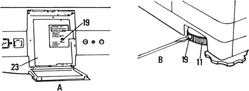
Figure 22-2 The transport lock A. To unlock the perspective control, remove the locking screw (19) completely. Close the lamp housing door (23) completely before using the projector. B. The locking screw (19) must be inserted into the perspective adjusting control wheel (11) before the perspective control can be moved.
Projection lamps can be replaced easily because the entire lamp holder is removable through the rear of the PCP 80. When changing lamps do not touch the new lamp with your fingers. Insert the pins of the lamp into the socket while holding the lamp in the plastic envelope in which it is supplied.
For maximum screen brightness, you must center the lamp in front of the mirror by watching the filament and its reflection while moving the lamp in any one or all three of the possible directions (see Figures 22-4 and 22-5).
After reinserting the lamp holder, close the inside cover completely. If lamp 2 goes on without lamp 1 being burned out, push lamp holder (“d” in Figure 24-4) upward until it clicks into position.
To produce perfectly even corner-to-corner illumination, each projection lens comes with its own matched condenser lens, which can be changed after you set the perspective control at or near the 0 position (see Figure 22-3). Push the condenser completely into the projector until it snaps into place. The control lever must also be set to the proper position, which is 150 for the 150 and 75mm lenses, and 250 for the longer lens.
The projector and the slides are kept cool with filtered air drawn into the projector from the bottom. The air filter underneath the projector can easily be removed for cleaning, something that should be done occasionally. Clean it by washing it like air filters in other equipment. Make certain that the filter is dry before it is used again. Make sure that the opening for the filter underneath the projector is open. Don't project on a tablecloth or other flexible material that may block the opening.
A resettable fuse at the bottom of the projector pushes out if the projector overheats. After the projector has cooled off, press the fuse to reset it. However, you should always investigate the cause of overheating before resetting the fuse.

Figure 22-3 Condenser lenses You insert or remove the condenser lenses (9) after lifting off the side cover (26). The condenser can be pulled out or inserted only if the perspective control adjustment (10) is at or near 0. The perspective matching control lever (8) must also be set based on the focal length of the lens.
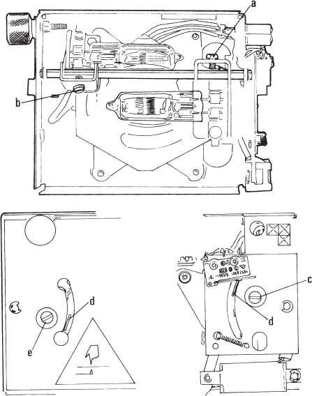
Figure 22-4 Lamp holder adjustments You remove the lamp holder by opening the rear door, unscrewing the large knurled knob on the upper left, and pulling out the lamp holder. You can align and center the two projection lamps after loosening the screws (a, b, c). If the lamp holder has switched to lamp 2 without lamp 1 being burned out, slide the metal tongue (d) to the upper position.
Attaching and Removing the Slide Trays
The slide tray can be attached in any position, but you must push the guide pin to the side if it is not in position 1. To attach a slide tray, be sure that the tray lock is in the unlocked position. The control can be turned from Lock to Unlock only when the projector is connected and the main switch is on. In the unlocked position, a red LED above the lamp's OFF switch is lit up, and none of the projector's operating switches works. You can project only if the tray is locked properly. Turn the tray lock knob until the red light disappears.
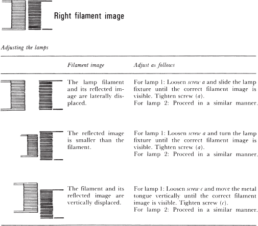
Figure 22-5 Aligning the projection lamps.
Table 22-1 Projection Distances and Screen Sizes

The slide tray can be removed only when all slides are in the tray. If a slide is left in the gate, press the Edit button. This moves the slide from the projection gate back into the tray.

Figure 22-6 Calculating projection distances and screen sizes.
The PCP 80 Operating Controls
The PCP 80 projector is equipped with three electric motors. The main switch turns on the motor for the centrifugal fan. Should the fan fail to operate, a thermal circuit breaker cuts off the power to the lamp. Such a failure would light up the HIGH TEMP LED. The 12V DC motor that operates the slide-changing mechanism is operated by the slide-changing, edit, and reset controls. The other 12V DC motor is operated by the focusing controls and moves the lens forward and back. The total power consumption is about 350W. All slide-changing functions are controlled electronically, making slide jamming almost impossible regardless of how you operate the controls.
Slide changing, forward and reverse, and lens focusing can also be operated with the Hasselblad remote control, which as a 13-foot cable that is connected to a six-pin DIN socket 25. The forward and reverse projection functions can also be operated with a standard Kodak remote control connected to the five-pin socket in the AV door at the rear of the projector. This door is found on all PCP 80 projectors sold in the United States. Dissolve and programming units made for U. S. Kodak projectors are connected to the same outlet.
Figure 22-7 shows how to start the PCP 80 projector, and Figure 22-8 shows the machine's operating controls.

Figure 22-7 Starting the projection A. The power cable is connected to the socket (22). The fan is turned on with the power switch (23). B. Slide trays can be attached only when the tray lock (12) is in the unlocked position, with the red control lamp burning. The slide-changing arm (a) is then in the up position. If the lock cannot be moved to Unlock, press the Edit button to bring the arm up. D. Attach the slide tray so that its groove (c) engages in the sensor (b) for the 0 position. C. To attach the tray in any position other than 0, move the sensor outward.

Figure 22-8 Operating controls A. The left side control panel has the lamp ON (14) and OFF (15) switches. When lamp 1 is on, the green light (a) is lit. If the yellow lamp (b) is also lit, projection lamp 2 is on, meaning that lamp 1 is burned out. If only the yellow indicating lamp (b) is lit, the projection lamps have been interchanged, but lamp 2 is not lit, or both lamps are burned out. The red lamp (c) is lit either when the magazine lock is not securely locked or when the projector has overheated. B. On the right control panel, you have the forward and reverse slide-changing switches (16). You move the lens forward or backward for focusing by pressing the front or rear position of the switch (17). Pressing the rear (a) of the switch (18) moves the slide back into the tray without advancing the tray. Pressing the top portion (b) turns off the projection lamp and moves the tray to the first position, where it stops.