
18
Close-Up Photography
FOCUSING RANGE OF HASSELBLAD LENSES
Hasselblad lenses, like all lenses, can be focused down to a certain minimum distance, which depends mainly on the lens design and the focal length of the lens. All lenses can be used at closer distances in combination with closeup accessories. Used at closer distances with accessories, the lenses behave as they do at longer distances. The lens-to-subject distance determines the perspective. Different focal length lenses cover different background areas and blur the background more or less. You can cover the same area from different distances with different focal length lenses.
The distance between the lens and the subject in close-up photography is often called the working distance. Some applications—such as photographing surgery, dangerous activities such as welding, or timid insects—call for long working distances, so you want to use longer focal length lenses. When you are working on a copy stand or at high magnifications, a shorter focal length is preferable because it reduces the possibility of camera motion affecting the picture sharpness. You can also select a specific focal length lens, such as 120mm, because the lens, the Makro-Planar, is designed optically to produce the best image quality in close-up work.
MAGNIFICATION
Magnification is the ratio in size between the actual subject and the size of its image recorded in the camera (see Figure 18-1). The most practical way to determine magnification is to relate the area coverage to the size of the image format, which is also the size of the focusing screen and which is 55mm for both sides of the 2¼-inch square and for the long side of the 6 × 4.5cm rectangular format. If you cover an area 220mm wide, the magnification is 55 divided by 220 = 0.25, or 1 : 4, or ¼. A ½ × magnification, also written 1 : 2, means that the image is half the size of the subject; 2×, or 2:1, means the image is twice the size.

Figure 18-1 Magnification 1. Magnification is the relationship between the size of an actual subject and the size of its image, as recorded in the camera or seen on the focusing screen of the camera. 2. If the subject area is about the same size as the screen, we have 1 : 1 magnification (A); when the subject area is twice as large we have 0.5, or 1 : 2, magnification (B). When we fill the screen with a small subject half as large as the negative, we have 2×, or 2 : 1, magnification (C).
USING CLOSE-UP LENSES
Close-up lenses, sometimes called diopter lenses, are positive lens elements that are mounted in front of the camera lens like a filter. They allow photographing at close distances. They can be used on any type or focal length of lens, but adding such a lens element affects the image quality of the lens. Stopping down the lens aperture reduces the loss of sharpness to an acceptable level for many applications.
Close-up lenses can be considered for close-up work with the XPan camera, for which no other close-up accessories are available. Close-up lenses are not recommended for critical photography with Hasselblad V or H system cameras, and the Proxar close-up lenses that used to be available are no longer made. The focal lengths of the Proxar lenses, which are 2 meters (79 inches), 1 meter (39½ inches) and 0.5 meters (193/4 inches), are also the maximum distances at which these Proxar lenses can be used with any focal length lens set at infinity. You can photograph at somewhat closer distances by turning the focusing ring on the lens away from the infinity setting. The distances are measured from the subject to the Proxar lens, not the image plane. Proxar lenses do not require an increase in exposure.
EXTENSION TUBES AND BELLOWS
Consider extension tubes or a bellows for quality close-up photography with all Hasselblad SLR camera models (see Figure 18-2). The bellows is another good option in the V system.

Figure 18-2 Extension tubes and bellows 3. Extension tubes and bellows serve the same purpose: to move the lens farther away from the image plane. A bellows extended to the same length as a tube produces the same magnification and image with the same lens. 4. Based on the formula E = M × F, the necessary length of an extension tube or bellows for a 0.5 magnification is 40mm for an 80mm lens, and 75mm if the focal length of the lens is 150mm.
Extension tubes and bellows serve the same purpose in close-up photography. Both accessories are mounted between the camera and the lens, for the purpose of moving the lens farther away from the image plane. They increase the image distance without any optical components.
A few basic facts are worth knowing:
• The longer the tube or bellows with a particular focal length lens, the closer the distance at which you can photograph, and consequently the smaller the area coverage and the higher the magnification.
• Shorter focal length lenses used with the same extension tube or extension on the bellows give a higher magnification and a smaller area coverage than longer lenses.
• You can cover the same area with a shorter focal length lens and a shorter tube or bellows extension, or with a lens of longer focal length combined with a longer tube or extension on the bellows. The two differ in the working distance.
You can determine the necessary length of extension with specific lenses from the following formula:
Length of extension = focal length of lens × magnification
For example, the extension necessary to obtain 0.5× magnification with an 80mm lens is 80 × 0.5 = 40mm; and with a 120mm lens, 120 × 0.5 = 60mm. Knowing this relationship is valuable, because it eliminates time-consuming experimenting, moving of cameras, and adding and changing of lenses and accessories.
The above formula applies to most lenses where the focusing is achieved by moving the entire lens but does not apply with lens designs that have a long distance between front and rear nodal points and feature optical focusing. That is the case with most HC lenses and lenses such as the CFE 350mm, the new CFE 40mm, the FE 60–120mm, or the FE 300mm. Consult the closeup charts at the end of this chapter.
DEPTH OF FIELD
As mentioned in more detail in Chapter 13, when covering an area of a specific size, as is always the case in close-up photography, you determine depth of field only by the lens aperture and the magnification; depth of field is the same regardless of the focal length lens you use. You can increase depth of field only by closing the lens aperture or covering a larger area. Depth of field becomes about twice as large when you close the aperture two stops. Although the depth of field is the same with all focal length lenses, the blur beyond the depth of field falls off more rapidly with a longer lens. At close distances, the depth-of-field range is more evenly divided, with about one-half in front and one-half behind.
Because depth of field is determined only by the magnification and the lens aperture, we can make a simple depth-of-field chart that applies to all cameras and lenses. The chart shown in Table 18-1 is based on an f/11 lens aperture. Note the limited sharpness range in close-up photography.
Column A is for general close up work based on a circle of confusion of 0.06mm (1/400 inch) which is used for the calculations of the depth of field scales in the V system. Column B is for critical work based on a circle of confusion of 0.03mm (1/800 inch). Depth of field scales and charts in the H system are based on a circle of confusion of 0.045mm (1/600 inch).
Table 18-1 Depth of Field at Various Magnifications
| Total depth of field inmm at f/11 | ||
| Magnification | A | B |
| 0.1× | 100 | 50 |
| 0.2× | 30 | 15 |
| 0.3× | 15 | 7 |
| 0.5× | ||
| 0.8× | 3 | 1.5 |
| 1× | ||
| 1.2× | 1.5 | 0.7 |
| 1.5× | 1 | 0.5 |
| 2× | 0.8 | 0.4 |
| 3× | 0.4 | 0.2 |
EXPOSURE
You obtain correct exposure in close-up photography in the same fashion as at longer distances, making certain that the meter reading is based on the small area being photographed. Holding a graycard over the subject and taking the reading of the graycard are often a good approach with reflected exposure meters. A metering system built into the camera or prism finder offers a definite advantage because you can see exactly the area that is measured by the meter.
A metering system built into a camera or prism viewfinder also eliminates the need for considering the necessary increase in exposure when you use extension tubes or bellows. Whatever the built-in meter says should be correct because the light is measured through the close-up accessory.
When the meter reading is made with a separate meter, the necessary exposure factor must be considered. Because extension tubes and bellows move the lens farther from the image plane, the light is spread over a larger area, and less light reaches the image area. The necessary increase in exposure is based on the ratio between the focal length of the lens and the length of the added extension, at least for the type of lenses normally used for closeup work. The required increases in exposure for the V system lenses and accessories are found in the close-up charts in this book. Such charts should not be necessary for determining exposure in the H camera system since the built-in meter is undoubtedly used for this purpose. Such charts are also included-in this book mainly to show the close-up capabilities with the HE extension tubes and the various HC lenses. If you want to know the increase or want to determine it for other cameras when you use a handheld meter, use the following formula:
![]()
Here is an example for f/16 on the meter, a 120mm focal length, and a 56mm extension tube:
![]()
The above formula, like the one for life size magnification, applies to many lenses with mechanical focusing but is not strictly correct for lenses with optical focusing as found in most HC types. It also depends on whether the lens has front or rear focusing. The formulas also may not apply with lenses where front and rear nodal points are separated extensively as often is the case in retro focus and telephoto types or with lenses where the exit pupil is not located about one focal length in front of the image plane. Consult the charts at the end of the chapter for exact correction figures. Since exposures with H system cameras are undoubtedly always determined with the built-in metering system, all of the above lens design information is included just for theoretical completeness. The information need not be considered and remembered while doing close-up photography. The same applies to 200 system cameras and all the other models equipped with a meter prism viewfinder.
LIFE-SIZE MAGNIFICATION
Life-size, or 1 : 1, magnification is achieved when the length of the extension tube or the bellows extension is equal to the image length of the lens. In life-size magnification, the subject distance is equal to the image distance, with the total distance between subject and image plane being 4× the focal length of the lens. The necessary exposure increase is 2f stops, and the total depth of field at f/11 is 2mm (see Figure 18-3).
TELECONVERTERS FOR CLOSE-UP WORK
Because teleconverters increase the focal length of a lens while maintaining its minimum focusing distance, they can be used to cover smaller areas without the need to move closer to the subject. The Makro-Planar 120mm lens, which covers an area about 8 inches (200mm) wide at the minimum focusing distance, can cover an area as small as 4 inches (100mm) wide when combined with a 2× teleconverter. Combined with a 1.4 teleconverter, it can cover an area 6 inches (150mm) wide without the use of any close-up accessory.
Combining Extension Tubes with Teleconverter/Lens Combinations
Extension tubes can also be used for close-up photography with a lens/tele-converter combination. The tube or tubes can then be mounted as usual between the camera and the lens/teleconverter combination. The tube or tubes are attached to the camera, and the lens/teleconverter combination is attached to the front of the tube or tubes.
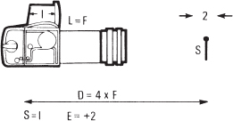
Figure 18-3 Life-size magnification Life-size (1 : 1) magnification is obtained when the length of the extension tube or bellows (L) is equal to the focal length (F) of the lens (L = F). The distance from the subject to the image plane (D) is equal to 4× the focal length (D = 4 × F). The exposure increase (E) is always 2 f stops, and the depth of field at f/11 is about 2mm.
On the H camera and the HC lenses, image quality is slightly improved when the tube or tubes are mounted between teleconverter and lens. The teleconverter is now attached to the camera, the tube or tubes are attached to the converter, and the lens goes in front of the tubes. This arrangement also provides a somewhat higher magnification but may produce a somewhat higher light falloff at very high magnifications. The same mounting arrangement can be suggested when the 2× extender is used in combination with the CFE 120mm Makro-Planar.
THE HASSELBLAD CAMERAS IN CLOSE-UP WORK
The single-lens reflex concept of all Hasselblad cameras (except the Super-wide and XPan models) is ideal for close-up photography. The focusing screen on H cameras and all the newer V models with the gliding mirror concept show the full image covered with any lens and any close-up accessories.
Earlier V system cameras have a cut-off at the top when bellows or extension tubes are used. The cut-off is minor with shorter tubes but may extend to about ¼ inch with longer tubes or extensions on the bellows. This vignetting is caused by the mirror and appears only on the focusing screen, not in the image. Allow for it when you make the composition.
Motor-driven film advance has an advantage in close-up photography because it eliminates the possibility of moving a tripod-mounted camera while the film is advanced manually. With motor-driven film advance, you can take sequences of identical images without time-consuming recomposing and refocusing. Locking up the mirror in critical close-up work is recommended with any camera.
Although most close-up work is best done from a tripod or camera stand, handheld photography is possible and can certainly be considered, especially with the automatic focusing in the H camera. In handheld photography with a manual focusing camera, you'll find that focusing is frequently easier if you preset the focusing ring on the lens and then move the camera back and forth until the subject is sharp on the focusing screen. You can hold the camera with both hands in the most convenient fashion rather than hold the camera with one hand while using the other to operate the lens. This approach works well even with a bellows.
CLOSE-UP PHOTOGRAPHY WITH THE H CAMERA
The built-in light-metering system, the possibility of automatic focusing, the focus aids, the extremely smooth lens shutter operation, the mirror lock-up capability, the availability of a Makro lens, and the many sophisticated features that can be programmed into the H camera make it a great tool for close-up photography. The HC4 120mm Macro lens must be the first choice for closeup photography. The focusing range of the lens goes from infinity down to a distance where it produces life-size 1 : 1 magnification covering an area as small as 55 × 41mm. Exposure and focusing can be automatic down to this minimum distance.
The H camera system also includes three extension tubes—13mm, 26mm, and 52mm in length—which maintain the electronic coupling to the HC lenses. The tubes can be combined if a longer extension is desired. Although the tubes can be used with all HC lenses, you want to consider the lenses 80mm and longer for close-up work. They provide the best image quality.
The 50–110mm zoom lens can also be used with the tubes, but the image does not stay in focus when the focal length is changed. Set the lens first at the focal length that covers the desired area; then focus the image manually or preferably automatically if the distance is within the automatic focusing range. See charts at end of chapter.
If the automatic focusing system does not work with a specific combination of lens and extension tubes, you will get a message on the LCD screen, AF NOT POSSIBLE WITH THIS LENS. Manual focus may still work.
Complete close up charts for the HE tubes and HC lenses are at the end of this chapter.
THE V SYSTEM CLOSE-UP ACCESSORIES
In addition to the bellows, four extension tubes are available for Hasselblad V system SLR cameras. The numeral in the designations 8, 16E, 32E, and 56E refers to the length of the tube in millimeters; the E indicates that the tubes have the electronic connections for the metering system in 200 camera models and therefore transfer the data from a CFE, FE, or TCC lens to the camera. You can use the older tubes without the E on 200 cameras, but you must manually close down the lens aperture for the meter reading, whether you use the focal plane or the lens shutter for the exposure. The E tubes can be used on all V system SLR cameras. The 8 tube does not have the E because it cannot be mounted on the 200 cameras. The shutter speed ring prevents it. The four extension tubes mentioned here replace the 10mm, 21mm, and 55mm tubes available in earlier years. Also available until a few years ago was a tube with variable length from 64 to 85mm.
All extension tubes can be used alone or can be combined. However, it is not recommended that you combine more than three tubes because the coupling between camera and lens may not perform with utmost reliability. For longer extensions, it is better to consider the bellows, combined, if necessary, with one or two tubes.
Choosing a V System Lens
All extension tubes can be used with lenses 80mm and longer, including the 350mm and 500mm focal lengths. The shorter extension tubes can be used with wide-angle lenses, but usually it is not a practical combination because the lens is too close to the subject, and the retrofocus wide-angle lenses do not produce the very best image quality. The Variogon 140–280mm and the Hasselblad 60–120mm zoom lenses can be used and do produce satisfactory image quality with the 16mm extension tube. The image, however, does not stay in focus when you are zooming.
The Makro-Planar 120mm (and the discontinued Makro-Planar 135mm) lens must be the first choice for close-up photography. These two lenses are optically designed to provide the best image quality at close distances and the very best at a 1 : 5 magnification, but they are also excellent lenses for use at longer distances. The 120mm Makro-Planar is in a standard mount with shutter and can be mounted on all V system SLR cameras directly or in combination with extension tubes or the bellows. The discontinued 135mm Makro-Planar has a special lens mount for use only with the bellows (or the discontinued variable extension tube). The Biogon 38mm is another lens that produces superb image quality at close distances, covering an area about 11 inches square at the 12-inch (0.3m) minimum focusing distance.
Attaching and Removing V System Extension Tubes and Bellows
The Hasselblad V system extension tubes and the bellows are equipped with coupling shafts that connect the camera and lens mechanism to maintain the automatic aperture close down and shutter cocking. Extension tubes and bellows mount on the camera exactly like lenses.
You remove extension tubes by pressing the locking button or lever on the tubes while the camera is in the cocked position. To remove tubes, it is of utmost importance to follow this procedure:
1. Remove the lens first from the tube, tubes, or bellows.
2. Remove the tube or bellows from the camera body.
If more than one tube is used, remove the tube farthest from the camera (the one that is closest to the lens). Then work toward the camera, removing each tube separately, removing the tube attached to the camera body last. Never remove a lens from a tube or bellows that is not attached to the camera. There is no tension to prevent the shaft from rotating, and it may uncock before the tubes and lenses are separated, jamming them together.
The same procedure should be followed with lenses attached to the bellows. Figure 18-4 shows the process of attaching and removing extension tubes. Extension tubes can be attached to the front of the bellows. The bellows cannot be attached to EL cameras equipped with the large square release. Replace it with a regular release button.

Figure 18-4 Attaching and removing tubes When you attach extension tubes (left), start at the camera by attaching the first tube to the camera. Then attach the second tube to the first, and finally attach the lens to the second tube. To remove extension tubes (right), reverse this sequence: First, remove the lens from the outermost tube, then the next outermost tube, and finally the tube attached directly to the camera.
Operating the Hasselblad Bellows
The V system Hasselblad bellows with a minimum extension of 63.5mm (22 inches) and a maximum of 202mm (8 inches) has a coupling shaft to maintain the mechanical camera and lens connection. It does not have the electronic coupling. The meter reading in 200 cameras therefore must always be made with the lens aperture closed down.
When you are working with a tripod, it is recommended that you use the tripod socket on the mounting plate of the bellows rather than the tripod socket on the camera. Mounting the bellows, rather than the camera, to the tripod head allows full use of the two adjusting controls, and that is a main benefit of using the bellows in close-up work.
The adjusting controls simplify and speed up close-up photography. With the bellows mounted on a tripod or stand, you change and adjust the lens-to-image plane distance by turning the lower knurled adjusting knob. The entire camera/lens/bellows combination moves back and forth without changing the distance between the lens and the image plane. It is basically the focusing control. You change and adjust the lens-to-image-plane distance (and thus the magnification) by turning the upper knob (see Figure 18-5). You may also want to use this knob for fine focusing because the image sharpness on the focusing screen changes more rapidly, thus making focusing more accurate. In actual photography, you will probably use both knobs more or less simultaneously, turning the lower knob until you cover the desired area and then using the upper knob to bring the subject into focus.
The 135mm Makro-Planar, now discontinued, was designed for use on the bellows with only a special rear mount to bring the rear element closer to the image plane. This design allowed using this lens/bellows combination not only for close-up photography but also for photography at all distances from infinity down to a close distance for life-size,1 : 1 magnification. The lens is focused for infinity at the shortest bellows extension of 63.5mm. At the longest extension of 202mm, the 135mm Makro-Planar covers a 2¼-inch area for life-size magnification.
An older, nonautomatic Hasselblad bellows interferes with the motor compartment of EL models. It can be used after you rotate the rear section 90 degrees so that the rail falls on the side. This older, nonautomatic bellows did not have the mechanical camera-to-lens coupling. Camera and lens functions had to be operated separately with the use of a double cable release. You must adjust the double cable release so that the various camera and lens functions follow this sequence:
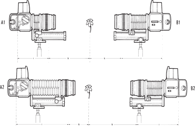
Figure 18-5 Bellows adjustments A1, A2. On the automatic bellows, the adjusting knob on the side of the engraved scale changes the extension of the bellows. It moves the lens, leaving the image plane stationary and thus changing lens-to-image plane distance, I, which determines the magnification. B1, B2. Turning the knob on the other side moves the entire camera setup (camera, bellows, lens) closer to or farther from the subject. It changes the subject distance, S, while maintaining the lens-to-film distance, I, and thus the magnification. This bellows operation is obtained only if the tripod or camera stand is attached to the bellows, not to the camera.
1. Lens shutter closes, and diaphragm stops down to preset aperture.
2. Mirror moves up, and rear curtain opens.
3. Shutter opens and closes at the set shutter speed.
HOW TO USE THE V SYSTEM CLOSE-UP CHARTS
In the accompanying charts (Figures 18-6 and 18-7), the close-up accessories are indicated as follows: P for Proxar lenses 2.0, 1.0, and 0.5; B 64-202 for bellows. The extension tubes are indicated by their length (8, 16, 32, and 56), including combinations of tubes, such as 56 + 8. The left end of each line indicates the values with the lens set at infinity; the right end is set at its minimum focusing distance.
To read the chart, follow horizontally in the space marked “Area coverage, size of subject” until you reach the number in inches or millimeters of the area (the size of the subject) that you need to photograph. Then go straight down vertically to see which close-up accessories cross the line, and then go farther down to find the depth of field at f/11, the necessary increase in exposure, and the magnification. The line may cross various close-up accessories, indicating all the available choices. For example, you can cover a 100mm (4-inch) area with a 120mm Makro-Planar with either an extension tube 56 or the bellows. Depth of field at f/11 is about 7mm, and exposure must be increased one f stop. Note that the indicated exposure increase applies only to extension tubes and bellows, not to the Proxar lenses.
HOW TO USE THE H SYSTEM CLOSE-UP CHARTS
All the necessary information for using the H system extension tubes successfully with different lenses on the H camera are shown in Charts A and B in the metric system with the dimensions in millimeters and in Charts C and D where the dimensions are in inches. Charts A and C apply when using just one of the three extension tubes with the different lenses, Charts B and D when combining two or three tubes. In all charts the information for the 50–100mm zoom lens is shown with the lens set at the 50mm and the 110mm focal length.

Figure 18-6 Close-up charts for 80mm to 250mm Hasselblad lenses.

Figure 18-6 Close-up chart for Sonar CF 180mm.

Figure 18-7 Close-up chart for bellows To read the chart, go from the bellows extension (120mm in this example) straight down until you reach the lens that is used (120mm). The number 2 indicates the necessary increase in exposure. Now go straight across to find the magnification (1 : 1) and the depth of field at f/11 (2mm).
Both Charts show the following details:
W means the size area included along the long side (the 55mm side) of the image with the lens set to infinity and the minimum focusing distance. If you like to know the area size along the short (the 42mm) side, multiply the listed figure by 0.76. For example if W is 7¼ inches, the area coverage is 7¼ × 5½ inches.
O is the distance from the subject to the front of the lens, which is the working distance.
M is the magnification range with each lens/tube combination.
R the required increase in exposure in EV values which, of course, needs to be considered only if the meter reading is made with a separate meter rather than the metering system in the camera. Using the built-in metering system in the spot, center-weighted, or averaging metering mode is obviously the recommended choice especially in close-up photography.
In all charts, the first figure in a column applies when the lens is focused at infinity, the second figure with the lens focused at its minimum focusing distance. For example a figure for W of 133/4–71/8 means that the lens covers an area 133/4 inches wide at infinity and 71/8 inches at its minimum focusing distance. A figure for M of 0.5–0.8 means that the magnification at infinity is 0.5 × and 0.8 × when the lens is set at the minimum focusing distance. The figures thus show the close-up photography range with that particular lens and tube or tube combination.
Figures that are in red indicate that the camera, lens, and extension tubes can be used for photographing at that distance but that the automatic focusing system in the H camera cannot be used; you must focus the lens manually.
Chart A
| Lens | Ext, tube 13 | Ext. tube 26 | Ext. tube 52 |
| 35mm | |||
| W | 151–119 | 77–67 | 39–36 |
| O | 78–55 | 29–23 | 5–3 |
| M | 0.4–0.5 | 0.7–0.8 | 1.4–1.6 |
| R | 1/3–1/3 | 2/3–2/3 | 1.0–1.0 |
| 80mm | |||
| W | 350–181 | 175–119 | 89–72 |
| O | 552–298 | 294–210 | 165–140 |
| M | 0.2–0.3 | 0.3–0.5 | 0.6–0.8 |
| R | 1/3–2/3 | 2/3–1.0 | 1⅓–1⅔ |
| 80mm + 1.7× | |||
| W | 207–108 | 106–71 | 53–42 |
| O | 551–298 | 294–210 | 165–140 |
| M | 0.3–0.5 | 0.5–0.8 | 1.1–1.3 |
| R | 1/3–2/3 | 2/3–1.0 | 1⅓–1⅔ |
| 150mm | |||
| W | 622–243 | 329–175 | 160–114 |
| O | 1786–731 | 925–557 | 495–392 |
| M | 0.1–0.2 | 0.2–0.3 | 0.3–0.5 |
| R | 1/3–1/3 | 2/3–2/3 | 1.0–1.0 |
| 150mm + 1.7× | |||
| W | 373–143 | 193–104 | 97–67 |
| O | 1785–731 | 925–557 | 495–392 |
| M | 0.2–0.4 | 0.3–0.5 | 0.6–0.8 |
| R | 1/3–1/3 | 2/3–2/3 | 1.0–1.0 |
| 50–110mm zoom | |||
| At 50mm W | 224–147 | 110–85 | 56–46 |
| O | 182–96 | 80–43 | 30–11 |
| M | 0.2–0.4 | 0.5–0.7 | 1.0–1.2 |
| R | 1/3–1/3 | 2/3–2/3 | 1⅓–1⅓ |
| At 110mm W | 467–164 | 233–114 | 117–72 |
| O | 935–277 | 486–198 | 261–129 |
| M | 0.1–0.3 | 0.2–0.5 | 0.5–0.8 |
| R | 1/3–1/3 | 1/3–1/3 | 1.0–1.0 |
Chart B
| Lens | Ext. 13+ 26 | Ext. 13+ 52 | Ext. 26+ 52 | Ext. 13+ 26+ 52 |
| 35mm | ||||
| W | 51–47 | |||
| O | 13–10 | |||
| M | 1.1–1.2 | |||
| R | 1–1 | |||
| 80mm | ||||
| W | 117–89 | 71–60 | 59–51 | 51–45 |
| O | 208–166 | 139–122 | 122–110 | 109–100 |
| M | 0.5–0.6 | 0.8–0.9 | 0.9–1.1 | 1.1–1.2 |
| R | 1–1⅓ | 1⅔–1⅔ | 1⅔–2.0 | 2.0–2⅓ |
| 80mm + 1.7× | ||||
| W | 70–53 | 42–36 | 35–30 | 30–27 |
| O | 208–166 | 139–122 | 122–110 | 109–100 |
| M | 0.8–1.0 | 1.3–1.6 | 1.6–1.8 | 1.8–2.1 |
| R | 1.0–1⅓ | 1⅔–1⅔ | 1⅔–2.0 | 2.0–2⅓ |
| 150mm | ||||
| W | 215–137 | 130–97 | 108–84 | 92–75 |
| O | 638–457 | 409–346 | 351–312 | 310–287 |
| M | 0.3–0.4 | 0.4–0.6 | 0.5–0.7 | 0.6–0.7 |
| R | 2/3–2/3 | 1⅓–1⅓ | 1⅓–1⅓ | 1⅔–1⅔ |
| 150mm + 1.7× | ||||
| W | 127–82 | 77–57 | 64–50 | 55–44 |
| O | 638–457 | 408–346 | 351–312 | 310–286 |
| M | 0.4–0.7 | 0.7–1.0 | 0.9–1.1 | 1.0–1.3 |
| R | 2/3–2/3 | 1⅓–1⅓ | 1⅓–1⅓ | 1⅔–1⅔ |
| 50–110mm zoom | ||||
| At 50mm W | 74–60 | 44–38 | ||
| O | 47–22 | 20–4 | ||
| M | 0.8–0.9 | 1.3–1.5 | ||
| R | 1.0–1.0 | 1⅔–1⅔ | ||
| At 110mm W | 156–89 | 93–61 | 78–52 | 67–46 |
| O | 336–156 | 216–111 | 186–98 | 164–68 |
| M | 0.4–0.6 | 0.6–0.9 | 0.7–1.1 | 0.8–1.2 |
| R | 2/3–2/3 | 1.0–1.0 | 1⅓–1⅓ | 1⅓–1⅓ |
Chart C
| Lens | Ext, tube 13 | Ext. tube 26 | Ext. tube 52 |
| 35mm | |||
| W | 6.0–4¾ | 3.0–2⅝ | 1½–1⅜ |
| O | 3⅛–2¼ | 1⅛–7/8 | 1/4–1/8 |
| M | 0.4–0.5 | 0.7–0.8 | 1.4–1.6 |
| R | 1/3–1/3 | 2/3–2/3 | 1.0–1.0 |
| 80mm | |||
| W | 13¾–7⅛ | 6⅞–4¾ | 3½–2¾ |
| O | 21¾–11¾ | 11⅝–8¼ | 6½–5½ |
| M | 0.2–0.3 | 0.3–0.5 | 0.6–0.8 |
| R | 1/3–2/3 | 2/3–1.0 | 1⅓–1⅔ |
| 80mm + 1.7× | |||
| W | 8¼–4¼ | 4¼–2¾ | 2⅛–1¾ |
| O | 21¾–11¾ | 11⅝–8¼ | 6½–5½ |
| M | 0.3–0.5 | 0.5–0.8 | 1.1–1.3 |
| R | 1/3–2/3 | 2/3–1.0 | 1⅓–1⅔ |
| 150mm | |||
| W | 24½–9⅜ | 13.0–6⅞ | 6¼–4½ |
| O | 70¼–28¾ | 36⅜–21⅞ | 19½–15⅜ |
| M | 0.1–0.2 | 0.2–0.3 | 0.3–0.5 |
| R | 1/3–1/3 | 2/3–2/3 | 1.0–1.0 |
| 150mm + 1.7× | |||
| W | 14¾–5¾ | 7⅝–4⅛ | 3¾–2¾ |
| O | 70¼–28¾ | 36⅜–21⅞ | 19½–15¾ |
| M | 0.2–0.4 | 0.3–0.5 | 0.6–0.8 |
| R | 1/3–1/3 | 2/3–2/3 | 1.0–1.0 |
| 50–110mm zoom | |||
| At50mm W | 8¾–5¾ | 4¼–3¼ | 2¼–1¾ |
| O | 7¼–3¾ | 3⅛–1¾ | 1¼–3/8 |
| M | 0.2–0.4 | 0.5–0.7 | 1.0–1.2 |
| R | 1/3–1/3 | 2/3–2/3 | 1⅓–1⅓ |
| At 110mm W | 18½–6½ | 9¼–4½ | 4⅝–2¾ |
| O | 36¾–10⅞ | 19⅛–7¾ | 10¼–5⅛ |
| M | 0.1–0.3 | 0.2–0.5 | 0.5–0.8 |
| R | 1/3–1/3 | 1/3–1/3 | 1.0–1.0 |
Chart D
| Lens | Ext. 13+ 26 | Ext. 13+ 52 | Ext. 26+ 52 | Ext. 13+ 26+ 52 |
| 35mm | ||||
| W | 2.0–1¾ | |||
| O | 1/2–3/8 | |||
| M | 1.1–1.2 | |||
| R | 1–1 | |||
| 80mm | ||||
| W | 4⅝–3½ | 2¾–2⅜ | 2¼–2.0 | 2.0–1¾ |
| O | 8¼–6½ | 5½–4¾ | 4¾–4¼ | 4¼–3⅞ |
| M | 0.5–0.6 | 0.8–0.9 | 0.9–1.1 | 1.1–1.2 |
| R | 1–1⅓ | 1⅔–1⅔ | 1⅔–2.0 | 2.0–2⅓ |
| 80mm + 1.7× | ||||
| W | 2¾–2⅛ | 1¾–1⅜ | 1⅜–1¼ | 1¼–1⅛ |
| O | 8¼–6½ | 5½–4¾ | 4¾–4¼ | 4¼–3⅞ |
| M | 0.8–1.0 | 1.3–1.6 | 1.6–1.8 | 1.8–2.1 |
| R | 1.0–1⅓ | 1⅔–1⅔ | 1⅔–2.0 | 2.0–2⅓ |
| 150mm | ||||
| W | 8½–5⅜ | 5⅛–3¾ | 4¼–3¼ | 3⅝–3.0 |
| O | 25⅛–18.0 | 16⅛–13⅝ | 13¾–12¼ | 12⅛–11¼ |
| M | 0.3–0.4 | 0.4–0.6 | 0.5–0.7 | 0.6–0.7 |
| R | 2/3–2/3 | 1⅓–1⅓ | 1⅓–1⅓ | 1⅔–1⅔ |
| 150mm + 1.7× | ||||
| W | 5.0–3¼ | 3.0–2¼ | 2½–2.0 | 2¼–1¾ |
| O | 25⅛–18.0 | 16⅛–13⅝ | 13¾–12¼ | 12¼–11¼ |
| M | 0.4–0.7 | 0.7–1.0 | 0.9–1.1 | 1.0–1.3 |
| R | 2/3–2/3 | 1⅓–1⅓ | 1⅓–1⅓ | 1⅔–1⅔ |
| 50–110mm zoom | ||||
| At 50mm W | 2⅞–2⅜ | 1¾–1½ | ||
| O | 1⅞–7/8 | 3/4–1/4 | ||
| M | 0.8–0.9 | 1.3–1.5 | ||
| R | 1.0–1.0 | 1⅔–1⅔ | ||
| At 110mm W | 6⅛–3½ | 3¾–2⅜ | 3⅛–2⅛ | 2⅝–1¾ |
| O | 13¼–6⅛ | 8½–4⅜ | 7¼–3⅞ | 6½–3½ |
| M | 0.4–0.6 | 0.6–0.9 | 0.7–1.1 | 0.8–1.2 |
| R | 2/3–2/3 | 1.0–1.0 | 1⅓–1⅓ | 1⅓–1⅓ |
SPECIAL CLOSE-UP APPLICATIONS
Slide Duplicating
Slide duplicates can be produced in professional laboratories, and it is often done digitally, which provides unlimited possibilities for changes and manipulations.
A simple way to produce your own dupes is to photograph the original transparency placed on a glass table using a camera mounted on a tripod and photographing straight down (see Figure 18-8). I use a tripod with the camera mounted on the tripod's reversed center post for this purpose. Align the camera so that the image plane is parallel to the glass surface.
The transparency is placed on an opal glass placed on top of the glass table. The opal glass, which diffuses the light to produce even light over the entire transparency surface, need be only somewhat larger than the transparency. The transparency is mounted on a black mask with a cut-out the size of the transparency. The mask holds the transparency flat and prevents unwanted light from shining directly into the lens. An 80mm, 120mm, or 135mm lens, in combination with the bellows, is most suitable for the V system. Extension tubes can also be used on V system and H system cameras. Their total length must more or less be equal to the focal length of the lens as discussed in Life-Size Magnification, earlier in this Chapter.

Figure 18-8 A slide duplicating setup A usable slide duplicating setup consists of a glass table (A) about 26 inches above the ground and an electronic flash unit (B) on the floor. An opal glass (C) on the table diffuses the light. The transparency (D) is on the opal glass. The camera is mounted on the tripod's reversed center post.
Electronic flash from a portable or studio unit shining directly on the opal glass is the recommended light source. A studio flash unit has the advantage of having a modeling light that can be used to align the transparency and to focus the lens. The power of the light source and its distance from the slide determine the exposure.
The dedicated flash system of the Hasselblad V and H system cameras should provide excellent exposures automatically, but test exposures are recommended.
Slide duplicating films are the best choices for duplicating slides. Unfortunately, they are not readily available, so you have to use the regular color slide films. Use the daylight type for use with flash.
Copying Documents
Photographs of documents must have edge-to-edge sharpness, good contrast, even exposure over the entire image area, and true colors if done in color. These results can be obtained beautifully and easily with Hasselblad cameras.
A quality copy requires that the plane of the document and the image plane be perfectly parallel to each other. If the object to be photographed has definite parallel lines, such as a picture, align the camera as carefully as possible so that the horizontal and vertical lines are perfectly parallel to the edges of the focusing screen. The focusing screens with engraved vertical and horizontal lines (checked screens) simplify this alignment.
Hasselblad used to make a linear mirror unit consisting of two optical plane mirrors, which allowed accurate alignment in a simple way. A large flat mirror went over the copy, and a circular mirror with bayonet mount was mounted on the V system camera. It has been discontinued because of limited demand.
For quality copying with the 500 V system cameras, consider using the Makro-Planar 120mm or 135mm lens or the Superwide cameras. The 110mm lens with the aperture somewhat closed down is a good choice on 200 V system cameras. The HC 4/120mm should be the first choice on the H system. Another good choice is the HC 2.8/80mm, if necessary, in combination with extension tubes.
The Copying Setup For copying large originals, you might find that a horizontal camera with the original mounted on a wall is best. For extensive copying of smaller documents, a special copying stand is recommended. Another sturdy setup for vertical copying results, if the center column of the tripod can be reversed so that the camera sits between the tripod legs, is suggested for slide duplicating.
Prereleasing the camera—locking up the mirror—is another good suggestion.
The automatic focusing of the H camera should be extremely precise with any type of copy subject. For manual focusing with V system cameras, place a substitute focusing target—something with small, very fine printing— over a copy subject that lacks fine detail.
Film, Filters, and Lighting For maximum sharpness, use a film with low sensitivity. When photographing colored originals on black and white film, you can use color filters to make certain colors lighter or darker, to increase or reduce the contrast, or to suppress or emphasize certain sections of the originals, as discussed in Chapter 16. A yellow filter, for example, can be of value when you photograph old, yellowed originals. The filter will lighten the yellow background and thereby increase the contrast.
Tungsten lights or electronic flash, especially studio units with modeling lights, are good choices.
Lighting must be even from corner to corner and must have no disturbing reflection. For small documents, one light may be sufficient, but two lights provide better possibilities for larger documents. Place the lights at equal distances on two sides, far enough away to cover the entire area and each at an angle of approximately 35 to 40 degrees. Check the evenness of the lighting by using an exposure meter, either an incident meter or a reflected type, in combination with a graycard. When you are working in color, the surrounding areas, walls, and ceilings may reflect light onto the original and change its color. It may be best to turn off all or most of the room lights and close curtains or shades to keep out daylight. Check carefully that nothing from the room, the chrome parts of the camera, the copy stand or tripod, or the photographer's white shirtsleeve is reflected on the copy, especially when you are photographing glossy surfaces.
Exposure can be determined with an incident meter placed over the copy with the cell pointing toward the lens. A reflected meter reading made with a handheld or built-in meter is best done and most accurate if you place a graycard over the copy and take the meter reading off the graycard. The exposure should be perfect regardless of what you are copying.
If polarized light is used as discussed in the next paragraph, the measurement is made with the polarizing filter over the lights. In addition, it is necessary to compensate for the polarizing filter on the lens if measurement is made with a separate meter.
Use of Polarized Light Copying results can be improved, often dramatically, with polarized light. It eliminates or reduces reflection and produces images that have higher contrast and better color saturation. Polarized light is recommended for all copying but especially for photographing colored copy, shiny surfaces such as glossy photographs or pictures under glass, and charts on black backgrounds. Polarization can make the background really black and make pencil lines and other marks disappear.
Because the subjects to be copied are at a right angle to the camera axis, a polarizing filter over the camera lens alone does not improve the results. You must also polarize the light that reaches the copy by using filters over the light source or light sources. For tungsten lights, sheets of polarizing material about 16 inches square work, but keep them at least a foot from the hot lights. I mounted mine in wooden picture frames. Such sheets can also be used for studio flash units (the recommended light source without heat problems) and with modeling lights that allow you to check the evenness of the lighting, something that is essential. When you are using a small portable flash unit, the polarizing filter need not be larger than the flash head. If two or more lights are used, each light must have its own filter, and the filters must be attached so that they polarize in the same direction.
The filters are usually marked, but if not, you can hold two sheets or two filters on top of each other and look through them while turning one. The sheets are polarized in the same direction when the most light goes through. Maximum polarization is obtained when the angle of the polarizing filter on the camera is 90 degrees to the angle of the filters on the light sources. This is known as cross-polarization. Turn the polarizing filter on the camera lens while visually checking the results on the focusing screen. A circular polarizing filter must be used on lenses in the H camera system.
Figure 18-9 shows a setup for polarized light copying.

Figure 18-9 Copying setup A simple setup for copying in polarized light consists of two lights (L), on the left and right, illuminating the copy from the same angle of about 35 degrees. The light from both lamps goes through the polarizing material (P1) so that the light falling on the copy is polarized. A polarizing filter (P2) on the camera lens is turned to produce maximum contrast. Exposure is based on a reflected or built-in meter reading off a graycard (A) placed on top of the copy or the reading from an incident meter.
HIGH-MAGNIFICATION PHOTOGRAPHY
With the Hasselblad close-up accessories and lenses, magnifications up to approximately 2× can be obtained. A simple solution for higher magnifications is to use special objectives that look like objectives for a microscope and have a standard microscope thread (see Figure 18-10). They can provide magnifications up to about 20×. Carl Zeiss used to make Luminar lenses for this purpose, but they are no longer available. Objectives for the same purpose should still be available from other companies, especially camera manufacturers that also manufacture microscopes—for example, Leitz or Nikon. The lenses can be screwed directly into the Hasselblad lens mount adapter, which is a simple aluminum block with a Hasselblad bayonet mount at one side and a center opening with a microscope thread. This accessory has been discontinued but can probably be found on the used-camera shelf. Mounting the lens mount adapter with the lens in front of the bellows is the best solution. To focus and change the magnification, you extend or shorten the bellows.
My high-magnification setup is identical to the one described for slide duplicating, with a tripod-mounted camera over a glass table. For transparent subjects, such as photographing and enlarging a small segment of a transparency, I use a studio flash unit on the floor as for slide duplicating. For opaque subjects, such as photographing a small area of a postage stamp, I use a studio flash unit shining on the subject from a 45-degree angle.
Electronic flash is the most logical light source because high-magnification photography requires a lot of light. Furthermore, with electronic flash, a camera or lens shutter is not really necessary as long as you work in a fairly dark room. Use the open flash method. Set the lens or camera shutter on B, press the release to open the shutter, and fire the flash manually. This approach eliminates all vibration problems. Exposure is best determined with an instant film test.
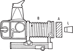
Figure 18-10 High-magnification photography The special lens (L) with microscope thread is screwed into the lens mount adapter (A), which is attached to the front of the bellows (B).

Figure 18-11 Photomicrography In photomicrography, the eyepiece forms the image on the film, so no camera lens is used. The microscope adapter holds the eyepiece and shields the camera from extraneous light. The eyepiece is dropped into the microscope adapter, and the adapter is then attached to the camera like a lens. The microscope adapter is no longer made. If you cannot find it on the used-camera shelf, you can undoubtedly construct a lighttight connection yourself.
PHOTOGRAPHY THROUGH THE MICROSCOPE
All Hasselblad SLR models can be used to record the image produced by a microscope (see Figure 18-11). A motor-driven model is recommended. Photography can be done with or without a lens on the camera, with the latter being the preferred method. If a camera lens is not used, a focal plane shutter camera can provide a variety of shutter speeds. An instant film magazine is valuable for checking exposure, lighting, contrast, and the reproduction of the various colors.
The quality of photographs is determined extensively by the microscope, its objectives, and its eyepieces but even more so by knowing which lighting and which optical system and arrangement produce the best results in a given situation.
I strongly recommend that you study special books, or even better, attend a special workshop to learn more about photomicrography.