We’ve covered a lot of topics up to this point. Throughout this book, you’ve looked at basic building techniques, like overlapping and stacking; different types of LEGO elements and how best to use them; and design ideas, like scale and color. Now it’s time to put your skills to use. This chapter focuses on you, the builder, working toward designing the models you want to make. So print out some design grids, dump some bricks out onto your building table, and get to work!
Note
You can find the design grids at http://nostarch.com/legobuilder2/, with complete instructions for using them in Appendix B.
You become a designer as soon as you step away from existing sets and prewritten building instructions. Whether you’re working from real-life inspiration or creating something completely original from your imagination, you’re designing. And as a designer working in LEGO elements, you have almost no boundaries.
Some people are a little bit overwhelmed by this sense of complete control. Although your head may be full of ideas, it may seem daunting to figure out how to turn those ideas into actual models. You may end up with a sketch pad that looks like Figure 9-1.
Figure 9-1. Freedom to create anything you can imagine can leave some people wondering what to build.
Sometimes knowing what to leave out of your project makes as much difference as what you put in. The term scope refers to the range of your model. It’s the answer to “What is the goal of my design?” and “How will I accomplish it?”
It’s easy enough to sit down at your build table and announce, “I’m going to build the Empire State Building! ” You decide that this model will be 20 feet tall, include hundreds of windows, and be made entirely from light grey bricks. It’s certainly possible to build such a model, but do you have the necessary pieces to build it now? Probably not. Its scope is just too ambitious.
So let’s start simpler.
Say you decide to build a copy of the Empire State Building. You look at your bricks and discover that you have plenty of dark grey, light grey, and white bricks. Why not use these colors to build your model? You don’t have very many transparent bricks or windows, so you can’t realistically re-create every window. You decide to use black bricks to simulate window openings. Finally, you decide that a 2- or 3-foot-tall structure is probably more reasonable than a 20-foot-tall one given the number of bricks in your collection.
You’ve determined a realistic scope for your project, one that’s much more achievable than your first idea. Setting reachable goals can help you succeed and ultimately help you be more satisfied with the time and effort you put into building.
Part of limiting your scope involves knowing what to leave out. In the Empire State Building example, one thing you left out was height. You reduced it to something realistic because the idea for the first model was too big for the average builder. You also substituted a part for a specific detail on the real building that would have been difficult to re-create otherwise: black bricks for windows.
In addition, you decided to mix colors so you could build a reasonably tall model with the bricks that you already have. In fact, most builders find that they usually need to use more than one color for their builds, regardless of the actual color of the object being modeled. But as with size, don’t let your color limitations limit your creativity. Look at what you have available and adjust your scope accordingly. For the Empire State Building, the use of greys, white, and black might actually make the model look more interesting than if you had built it entirely in a single color. Turn your limitations into features!
Defining the scope of your projects will also help you decide the level of detail to include. When building the Empire State Building, you’ll need to drop certain details in order to build to the reduced height, cutting elements like intricate details above windows and perhaps simulating where windows would be, rather than building each window. The same might hold true for doors and other street-level details.
Learning to build within boundaries is an excellent way to improve your skills, hone your artistic eye, and maximize the enjoyment you get from your existing collection of LEGO bricks.
When choosing the subject of your models, pick things that interest or challenge you on different levels. For example, try building tall, thin models (like the Empire State Building) to practice your column building techniques, or try to create realistic-looking buildings at different scales to practice working out the scale dimensions. But no matter what subject you pick, make sure it’s something that you like. You’ll spend a lot of time thinking about and examining your subject from many angles as you figure out how to best re-create it in LEGO pieces.
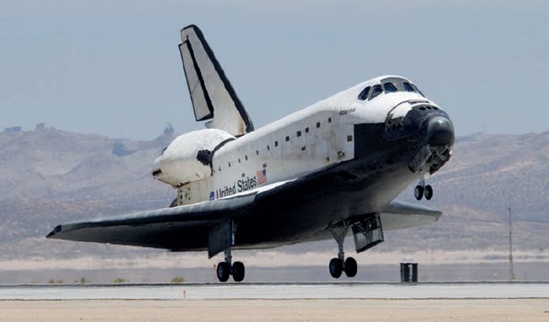
To illustrate as many design and building principles as possible, in the sections that follow we’ll create our own model of a NASA space shuttle, a subject that combines a good mix of shape, color, and construction challenges. I picked the shuttle because I’m a big fan of space exploration. Don’t worry if you’re not a spaceflight aficionado, as you can still apply the lessons from this exercise to a subject that does interest you.
Figure 9-2 is a photo of the space shuttle Atlantis, which we’ll use as inspiration to guide our design.
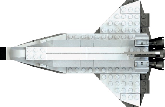
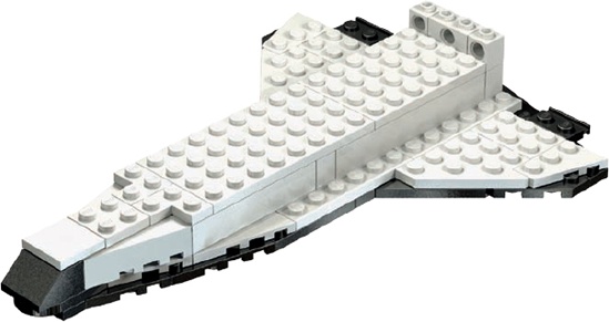
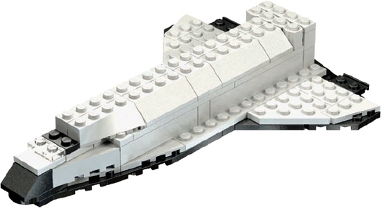
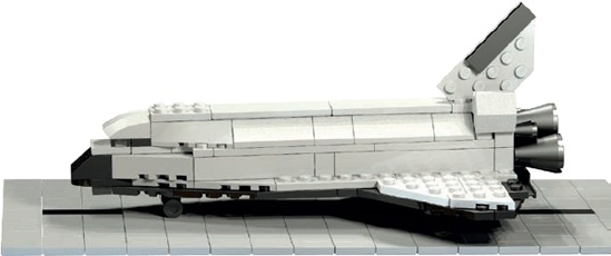
Although we’re going to work to a fairly small scale, your LEGO version of a space shuttle will still be very recognizable and will include a number of distinctive features inspired by the real thing. Figure 9-3 shows what we’re going to wind up with by the end of this chapter.
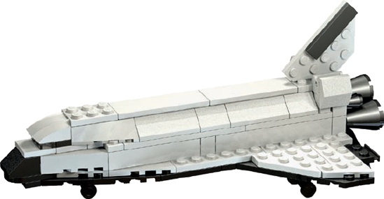
To add some originality, let’s call our model the Triton. That was the name of a ship that once sailed in the British Royal Navy and the name of Neptune’s largest moon, so I think it makes the perfect name for a fictional space shuttle.
Where do we start? Well, let’s look at the shuttle. What section should we build first? We could start with the tail, but how would we know to make it the right size? We could build the cargo bay doors, but could we easily attach them to the rest of the shuttle?
Rather than just jumping in, look at what you’re trying to duplicate. The shuttle has many distinctive features, but one stands out: its unique wing design (as you can see in the drawing I’ve made in Figure 9-4 using Design Grid #1).
Because the wings are effectively the bottom of the shuttle, they’re an excellent place to start modeling. With that question behind us, we can decide how to attach and accurately scale other parts of the ship to match the wings (kind of like modeling the ground floor of a building first so you know how wide and tall the remaining floors should be).
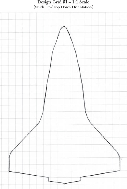
Figure 9-4. Copying the outline of your model from a photo or drawing can help you achieve realistic results.
I created the outline in Figure 9-4 like this:
I searched the Internet for a diagram that showed the shape of the shuttle wings from below.
I printed this image onto a sheet of plain paper.
I printed out a copy of Design Grid #1. This grid takes a top-down look at a model.
Finally, I put the printed image under the design grid and traced the outline of the wings. This gave me a very accurate reproduction of their shape, which helped me find LEGO pieces to match that outline.
Of course, the shuttle’s wings aren’t basic rectangles. To re-create them you’ll need tapered parts. Wing plates and diamond-cut plates (see Table A-3 in Table A-3 for sizes and shapes) will provide the shapes you need.
Creating the wings using the design grid is almost like putting together a jigsaw puzzle, except that instead of being given the pieces to assemble, you have to find suitable pieces in your collection and fit them to match the outline you’ve drawn on the grid. Notice in Figure 9-5 that I’ve used wing plates to form the outer shape and standard plates in the space between. You can set real pieces on top of your penciled-in design to test them out because the squares on the design grid are exactly one stud by one stud in size.
Together, these elements give you the foundation for your vehicle. Of course, the size and quantity of these plates might vary if you are designing this model based on your own collection of parts. For example, you might substitute standard plates for wing plates if you don’t have those parts. But the goal is the same, regardless of whether your shuttle is 10 studs long or 100 studs long: to make the model look like the real thing.
The method of finding one feature of an object upon which to base your model can apply to nearly every creation you take from real life. Just follow these steps:
Use a distinctive feature of the item being modeled. In the case of the Triton, we use the unique wings. When building a model of a train engine, you might select the crew cab. For a spaceship, you might start with the engines.
Choose the elements best suited to represent that feature. For the Triton, we chose wing plates to match the real shape of the wings that we drew on the design grids. Pay more attention to angles than size.
Build your model by incorporating elements that work together. As you finish the Triton, you’ll see that the choices we make for each section, along with the bricks we build with, are driven by the foundational elements of the model. In other words, the wings provide a reference for the rest of the model.

Figure 9-5. The LEGO elements are superimposed on a copy of the design grid with the outline of the wings drawn in.
That’s it for the basic wing design, but now we need to make a structural decision. How will we hold these pieces together? The easiest solution is to use the actual shuttle as our guide.
The portion of the wings we’ve built so far is a lot like the protective tiles that cover the underside of the shuttle. When you look at the real shuttle, you see that the upper part of the wings is almost the same size and shape as the underside, but it’s made from a different material than the tiles underneath.
To duplicate the look of the real wings, we can add a second layer of plates in a different color. As you can see in Figure 9-6, the second layer doesn’t exactly match the shape of the first, but that’s all part of the design. By working to re-create the parts on the actual shuttle, we end up figuring out how to hold the first layer of plates together.
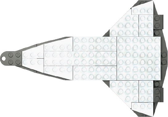
Figure 9-6. The second layer of plates (white) doesn’t quite match the first, but that’s a good thing.
If the second layer of plates were configured exactly like the first layer, nothing would hold them together. By selecting plates of different sizes and shapes, we make sure that the individual parts are arranged to take the best advantage of the overlap technique.
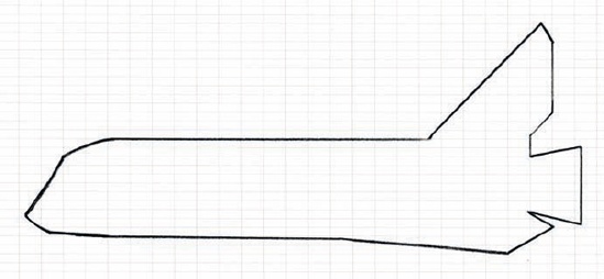
So far, we’ve been using only Design Grid #1, which looks down on a model from above. This grid is good for estimating the length and width of a model as well as its overall shape, but it doesn’t allow you to see its height. To have a look at our model’s height, we’ll use Design Grid #4 to show the Triton from the side.
Each small rectangle on this grid represents a 1×1 plate as seen from the side. You can use this perspective to decide how many layers of bricks or plates you need to achieve your goal height. For the Triton design, we’ll use the landscape-oriented Design Grid #4. This sheet is longer than it is tall, so it’s a good fit for the shuttle.
As you can see in Figure 9-7, you can use the side-view grid to plan the model’s height (roughly three bricks high) and determine the location of key structures like the tail and engines.
As you draw your plan, don’t worry about making your sketch fit the lines on the design grids exactly. You’ll end up making compromises between what you draw and what you actually build. Compromise isn’t a bad thing; in fact, it’s often the source of the most inspired ideas. Sometimes not having the perfect piece leads you to use another piece (or pieces) that actually ends up being a better solution.
Choosing a scale for any original model is one of the key decisions you’ll make. We’ve talked about scale a number of times already. For our model of the space shuttle, we’ve let the design of the wings and how it matches available wing plates set the scale. In other cases, you might pick a scale in advance and build everything to that size, like the train station we built in Chapter 3.
Because this is an original model, you get to choose the scale. Of course, if you’re trying to match the size of another model, you’ll need to work to that scale; otherwise, choose the scale that you think is best for your project.
Like scale, the choice of colors is up to you. And don’t underestimate the importance of color. Color can change the way that people react to a model. For instance, a sculpture of a dog made out of blue bricks might make people think of a cartoon character rather than a real pet.
Combinations of colors can also have a dramatic effect on how people react to your work. For example, a helicopter built from primarily white bricks with red accent pieces will probably make most people think of an air ambulance. But build the same design with black or dark grey bricks and the result looks like a military or police vehicle. Similarly, color combinations can evoke particular themes or settings. Bright colors like red, yellow, and blue might suggest an amusement park ride, whereas a building made out of mostly grey bricks might feel more like a warehouse or a factory than a comfortable home. As you design your model, consider the colors you’re using to see if they represent the theme or the feeling you’re trying to convey.
Picking colors for the Triton isn’t that tricky; you can let reality guide you. The real shuttle is mostly white, dark grey, and black—the standard NASA color scheme. By sticking to these colors you add realism to your model despite its small size. And, as you can see in Figure 9-8, the black and white bricks create a dramatic contrast that brings out some of the main features of the ship.
No matter what you’re planning to build, there are certain elements to keep in mind. We’ll focus on four major attributes: shape, color, proportion, and repetition.
What shape will your model be? There is a reason why cars aren’t shaped like trees. Think about the form you’re trying to create. Plain, flat walls can be boring, so don’t forget to include curves, angles, indents, and other interesting surfaces in your models to make them look more interesting.
In building the Triton, we’re trying to re-create the shape of the original shuttle. Shape is one of the most important attributes when working from real life. In Figure 9-9, you can see that I’ve selected specific plates for the wings and slopes for the top of the body that most accurately represent the real thing.
Will you be working with only a couple of colors or a whole range? Your choice of color can affect the overall impression the model makes, especially when combined with the shapes you use.
We let reality guide us when building the Triton and we chose the NASA color scheme of black, white, and shades of grey (Figure 9-10). But you could build the Triton in different color schemes. Perhaps a black and yellow version could be a construction shuttle, destined for a space station? Or a red and white version could be a rescue shuttle, standing by in case of emergency?
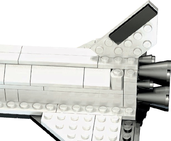
Are the model’s substructures all the same scale? For example, if you build the doors and windows on your model to the same scale, it will look more realistic. The real shuttle is a complex flying machine. To make the Triton emulate it, you need to retain the correct balance between the length of the body and the width of the wings. You have to make sure that the tail (Figure 9-11) is tall enough but not too tall and not too thick. You need to design the wings to be strong enough to serve as the base of the model but thin enough to look like they could fly.
Rows and rows of 2×4 bricks can be boring, but a few rows of arches can be beautiful. Sometimes repeating the same shape can add dimension to your model. Just be sure to select an interesting shape before you add too many to your creation.
The Triton uses repetition by employing 1×6 tiles (Figure 9-12) along the top of the cargo bay doors, giving at least the impression that they might open. In fact, the doors themselves, made from 45-degree slopes, are another example of where repetition can help add authenticity.
It’s finally time to build the Triton. In the pages that follow, you’ll find building instructions and notes for each step. Figure 9-13 lists the pieces that you’ll need to make this model, but don’t forget that substitution is a regular part of building original models. If you don’t have every piece shown in the BOM, try to find substitutions—and be creative!
Official instructions for most LEGO models don’t include many words. Typically, the company relies on images to show you how to put together the set you’ve bought. Because we’re looking at the design process in this chapter, I’ve included detailed notes on each step. I want to explain why we’ve made certain design choices and how those choices affect the outcome of the final model.
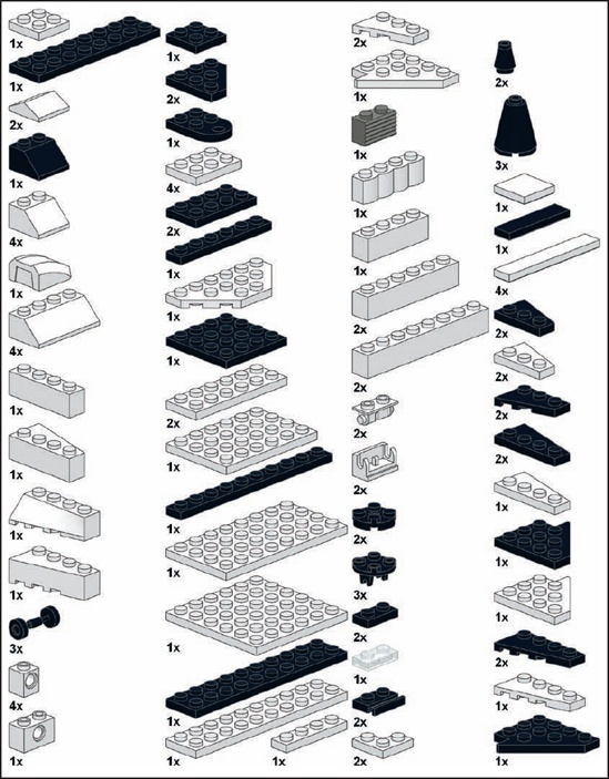
Figure 9-14 shows the bottom layer of the wing structure, similar to Figure 9-5.
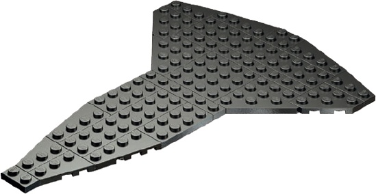
The wings serve as an excellent base upon which to build the rest of the craft.
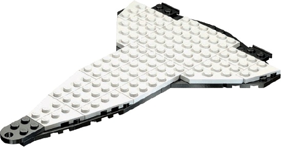
The second layer of plates (Figure 9-15) follows the outline of the lower layer closely but not exactly. This slight mismatch is a design decision. The real shuttle’s wings have some of the protective heat-absorbing material lining their front edges. By exposing some of the lower layer, we create the illusion of that material on the model. (This is a variation on the staggering technique.)
The body of the shuttle model is simple because at this scale there isn’t much room for detail. As you can see in Figure 9-16, we’re concentrating on creating the basic outline for the cargo bay.
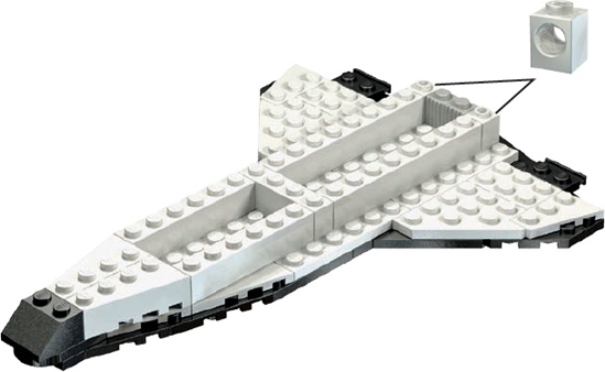
Figure 9-16. The image at the top-right corner gives you a building hint. One 1×1 Technic brick goes on each side of the 1×2 grille brick.
You’ll always need to make similar decisions about detail when you create your own models. Try to design realistically, but don’t overwhelm a small model with more details than it can handle. Ultimately, ask yourself, “Does this model look the way I want it to?” As long as the answer is yes, you’ve got a successful design.
Because this model isn’t meant to be functional, we don’t need to create a hollow cargo bay. Instead, we’ll use 4×N plates (Figure 9-17) to join the side walls.
This makes for a sturdier ship that holds up better to being whooshed around the room. A larger-scale model of the shuttle could have included such things as retractable landing gear or movable wing flaps, but it would have been difficult to try to make those features work on this small scale. It’s up to you to decide how many details to include based on the size of your project.
The Triton model is fairly small, so it comes together quickly. In Figure 9-18, you see that by Step 5 we’re already adding the 45-degree slopes that form the cargo bay doors. (Remember, the doors aren’t functional—they are only for show.)
You can sometimes add several unrelated portions of a model in the same building instruction step, as you can see in Figure 9-19.
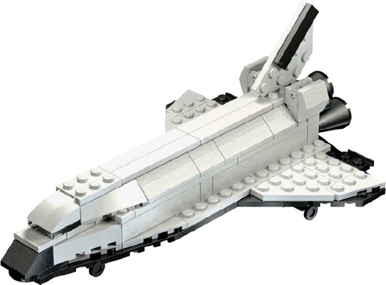
Figure 9-19. As long as nothing is blocked from view by the new elements, you can add any number of pieces in a single building instruction step without causing confusion.
Here, we added the tail (mounted on a 2×3 plate), the cowlings near the engines (the 2×2 33-degree peaks hanging off the 1×2 hinge bricks), and the curved slope that becomes the top of the crew cabin.
Use a black 1×4 tile on the tail to represent some of the protective tiles on the real shuttle. Don’t worry about re-creating the specific movable parts of the tail (at the rear). If you add too much detail, you may take away from the look of the rest of the model. Don’t add more detail in one area if you are keeping other areas sparse.
The tail is held in place by the studs on the 2×3 plate below it. Because the thickness of the plate is nearly identical to the distance between the studs, it can be wedged in.
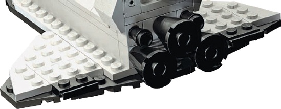
Sometimes you’ll need to turn your model one way or another to more clearly see a building step. For example, in Figure 9-20, we turned the Triton so that the tail section was facing toward us. This allows us to see where the 1×1 and 2×2×2 cones should go to create the engines.
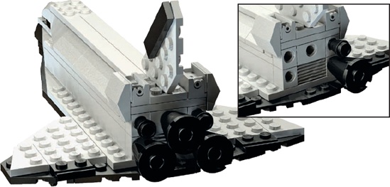
Figure 9-20. Now you see why I used Technic bricks to build the end of the body. The inset shows the rear of the shuttle without all the cones in place.
Although the engines might not be exactly the right size for this scale, they are very close. Also, they match the pattern in which the engines are mounted on the real shuttle fairly accurately, which makes your micro model look more like the real thing. Remember, we’re capturing the look, not the minutest detail.
In Step 8, reposition the ship as shown in Figure 9-21. This time, we’re looking at it from underneath so that we can see where to attach the landing gear.
When you’re adding pieces to the underside of another element, count the tubes to see where to make the attachment. When you’re adding pieces on top of others, use the studs as guides instead.
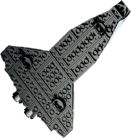
Figure 9-21. Using only a picture and no words, I can accurately describe where to attach the landing gear on the lower wing.
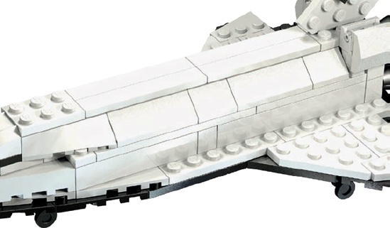
The two sets of wheels closer to the back of the Triton are mounted slightly differently from the front landing gear. Each rear wheel has a 2×2 cylinder plate sandwiched between the wheel and the shuttle’s underside. This causes the nose of the craft to sit slightly lower when it’s finished, as you can see in Figure 9-22. This effect duplicates the angle at which the real shuttle points when it is taxiing after a landing.
Figure 9-22 reveals that Step 9 isn’t really a step at all, but a view of what the completed model should look like.
You might want to use this last step to determine where to add decals (printed from your computer) or small detail pieces. In Figure 9-22, I added a runway made of tiles beneath the model to enhance the realism.
Don’t be concerned if something in your model isn’t quite right. Remember, you’re building with LEGO bricks. You can take everything apart and put it back together! Disassemble the section you feel is lacking and rebuild it with different pieces, combinations of pieces, or alternative colors.
For the Triton, I built a prototype first, and then I rebuilt the nose two or three times before I hit on the combination of plates, tiles, and slopes that I felt best represented the shape I wanted. I also adjusted the pattern of plates I used to make the wings several times until I felt they looked right but were also strong enough to support the pieces I was going to add on top. The engines, on the other hand, just seemed to work right off the bat.
Not every section of a model will come together perfectly on your first attempt. Some turn out exactly as you intend, while others will require changing parts or techniques again and again until things begin to look better.
Now you’ve seen how to design and build an original model from scratch. You’ve looked at various ways to capture details from real-life objects and how to make wise design decisions when translating an object into LEGO pieces. But when you’re done, what’s next?
The first thing you’ll probably want to do once you finish a model is to display it where other people can see it. If you’re displaying it on a shelf somewhere, you may want to build something to set your model on (like the runway in Figure 9-22), or you may even make it part of a complete diorama.
You can also display your model online. Take pictures of it and display them on the Internet for your friends and others to enjoy on sites like http://www.brickshelf.com/ or http://www.mocpages.com/.
You don’t have to be hired by the LEGO Group to be a model designer. The moment you decide to build something that’s never been built before, you are the designer. And that’s really what this book is about.
As a model designer, you will need to consider all the aspects of LEGO building—part selection, color choices, scope, and scale—to make good decisions about your models. But working through those decisions really adds to this hobby.
Whatever you build, enjoy!