The LEGO system is always adding new elements, colors, and modern set designs. But perhaps one of the more significant additions came in 1978 with the miniature figure, better known as the minifig (Figure 3-1).
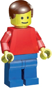
The years have brought us many different minifigs, from astronauts and cowboys to helicopter pilots and robots, wizards and witches, and everything in between.
When you build to a particular scale you make buildings and other constructions that would fit in a world of a particular size. When you build at minifig scale you’re building a world that the minifig would live in.
As you can see in Figure 3-2, in real life the basic minifig is just barely 1.5 inches tall. But from his point of view, he’s 6 feet tall! So now we can come up with minifig scale.
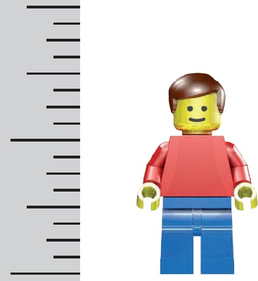
Figure 3-2. How does a minifig measure up? In our world he’s only 1.5 inches. In his world he’s 6 feet tall.
To convert to minifig scale, do the following:
Convert 6 feet (the minifig’s height in his world) into inches:
6 feet × 12 inches per foot = 72 inches Divide the minifig’s height in his world by his height in our world:
72 inches ÷ 1.5 inches = 48 inches Create your scale. Your minifig is 1:48 scale (pronounced “one-forty-eighth” or “one to forty-eight”).
Scale is shown as two numbers separated by a colon. The number on the left (1) represents size in the real world. The number on the right (48) tells us how many actual minifigs it would take (stacked on top of one another) to equal a minifig’s real-world height. In other words, if we stacked 48 actual minifigs, the stack would be about 6 feet high.
Once you have your scale, you can use it to determine how big a real-life object should be in your minifig world. For example, say you want to give the minifig a house that’s 24 feet tall in real life. The formula for calculating the height based on your scale is as follows:
| Real height ÷ Scale value = Size of scale model |
So to figure out how high the house should be in minifig scale, you divide its actual height (24 feet) by your scale value (48). Here’s how to do it:
Convert 24 feet to inches by multiplying by 12.
24 feet × 12 inches per foot = 288 inches Divide the result by the scale value (48) to determine the object’s size in minifig scale.
288 inches ÷ 48 = 6 inches
Your minifig-scale house should be 6 inches tall.
The rest of this chapter will focus on building a railway station to minifig scale. I’ll show you the parts that will go into the model and how to use the building techniques you’ve learned so far to build other buildings in your LEGO town.
As you read, remember that this building doesn’t have to be a train station. You can adapt it to be an ice cream parlor, hamburger stand, or even a ticket booth for a theme park or a zoo. You never have to color inside the lines when building with LEGO bricks.
We’ll tackle the building in two ways. First, we’ll build it as if it were an official LEGO set using a nearly unlimited range of parts. You can use specialty pieces to add details. Next, I’ll remake certain parts of the building using more common pieces, like those you might find in your own collection.
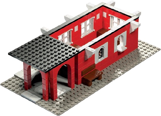
The station design is based on one you might find in many small towns across North America. A typical station constructed sometime in the late 1800s or early 1900s might look something like Figure 3-3. Often, these buildings shared common features like sloped roofs, arched entryways, and windows dressed in contrasting colors.
Before building the roof or other details, we need to make the basic building. I’ll use a simple overlap technique for the outside walls before incorporating some slopes to complete the roof design.

Figure 3-4 shows you the Bill of Materials (BOM; a list of parts with pictures of each) you’ll need in order to build this model. Even if you don’t have every piece listed, you can still build the model; just substitute! If you’re short on 1×8 bricks, replace each of them with two 1×4 bricks. If you’re missing one 2×2 brick in a certain color, stack up three 2×2 plates to do the same job. Use your imagination to substitute one or more elements when necessary.
Here are the steps for building your train station.
Notice the 1×1 bricks to the left side of the building in Figure 3-5. I’m going to use stacking to create very slender columns based on the simple post technique discussed in Chapter 2 (Figure 2-24 in Columns). When I’m done, I’ll have created six columns to support part of the roof. On their own, these columns are very weak, but when you use them together, and support them with arches, you’ll see they’re strong, and they look good too!
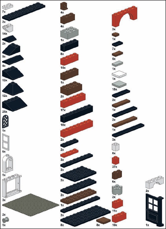
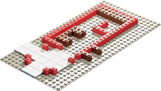
Figure 3-6 shows the model after I added the second course of bricks. I’m using overlapping for the main walls and stacking for the columns.
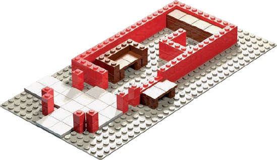
I’m using overlapping to create the counter in the station—the L-shaped interior wall near the top right of the model. This wall connects to the outside wall with a 1×4 brick, which keeps the wall from going anywhere when the train rumbles by.
There are three benches. The first is outside the station on two brown 1×2 log bricks. The second, inside the station, has armrests. The third, at the very top, is a long bench seat that minifig children can sit on to watch the trains go by.
Note
It’s usually best to add furniture and inner walls early on in the building process so you won’t have to take apart the walls or roof to add them later.
As the walls and columns rose, I installed the large windows, as shown in Figure 3-7. Plan ahead and decide early on where walls will meet, where windows should be, and which wall gets the door.

Note
Don’t panic if you don’t have windows like these. I’ll show you how to create simple replacements later in the chapter.
Near the center of Figure 3-7 are four brown studs facing outward, behind the bench. These are four headlight bricks lined up in a row (one of the specialized elements found in Table A-5 in Table A-5). Each of these 1×1 bricks has a traditional stud on top and one on one side. We’ll use them in the next step.
Things are shaping up. The door is in place and ready to let minifigs into the station to wait for their trains. I’ve added a small, arched window with a crisscross latticework screen to the right of the outside bench. The opening to its right is where the ticket agent can serve minifig customers. The 2×2 tile sticking out from this opening is the ticket window counter.
Figure 3-8 shows the completed outside bench. I’ve covered the fronts of the headlight bricks (where the studs face out) with a brown 1×4 tile, which will be the backrest for the bench.

Figure 3-9 shows how I added 1×6×2 arches to join pairs of columns. Pairs of columns like these can be used to support a roof structure.

With the outside walls almost complete, notice that the two windows at the front now have 1×4 arch bricks above them. These arched windows give the building a classic look. I’m using stacking on either side of the two arched windows to make it look like there are white frames around the windows. (See the result in Figure 3-3.)
Next I added the second set of inverted 1×2 slopes to help create the effect of arched supports for the roof, as shown in Figure 3-10.
Note
Although the LEGO system has an inverted half arch (see Table A-6 in Table A-6), I didn’t use it because it would have stuck out past the edge of the roof by one stud.

Figure 3-10. Be sure that all the lower layers are stabilized by longer bricks along the top course.
Notice how carefully I’ve selected the bricks for the top course in Figure 3-10. When possible, try to connect the lower courses of your building by overlapping the top layer across as many seams as possible. For example, look at the red 1×6 brick above and between the two arched windows. This brick is critical to making sure the 1×2s between the windows don’t fall out. (Remember, it’s okay to stack bricks as long as you add elements to hold them together.)
Another good example of overlap can be seen in the 1×6 that sits over the door to the building. We’ll use this brick to hinge the door, but it also connects the walls on either side of the door to each other. That’s an important 1×6 brick!
A roof at last! Well, at least some of the roof. The black plates on top of the 1×6 arches will become the base of the roof for that part of the station. To prepare for the rest of the roof, I’ve placed a series of tiles around the top of the main walls, as you can see in Figure 3-11. The reason I used those will be explained in the next step.
More black plates get added above the entryway (Figure 3-12). Those will raise the fixed part of the roof to perfectly align with the removable portion that I’ll show you how to build in Submodel: The Train Station Roof in Submodel: The Train Station Roof. The tiles around the rest of the walls are where the roof submodel will sit, without actually attaching to the station. That’s the reason why that section of the roof can easily come off!
Slopes make such good elements for building roofs that they are sometimes called roof bricks. Here, I’ve used 33-degree slopes to give the roof a gentle angle. I began the first layer of roof by adding slopes to the plates I added in the previous step. The 1×8 bricks running between the slopes will support the next layer of roof bricks, as you can see in Figure 3-13.

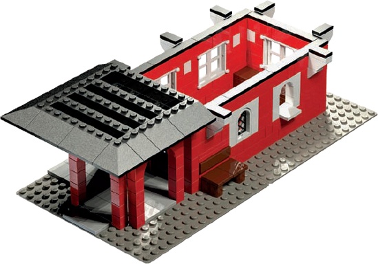
Figure 3-13. The rest of the roof is yet to come. For now, focus on the area directly above the entranceway.
Wait a minute, why only half a roof? I’m creating a nicely sloped and very functional roof but only for part of the station, because I want this project to be something that you can use as a static display or a play set. The tiles along the top of the main walls help create this dual functionality.
Notice in Figure 3-13 that the lowest layer of slopes extends from the sides of the building out as far as the half arches. When I reach the end of the model and reveal the rest of the roof construction, you’ll see that although they aren’t really attached, the inverted 1×2 slopes appear to support the roof.
As I added the next layer (see Figure 3-14), I overlapped the slopes, as with the 1×N bricks I used for the walls.

Like the 1×8 bricks in Figure 3-13, the three 1×4 bricks in Figure 3-14 will provide support for the layer of slopes above them.
Remember that color isn’t everything. Although my building has a black roof, as you can see in Figure 3-15, yours doesn’t have to be black. Red or blue slopes will work just as well, and you can change the colors of the walls to match, or not. Experiment with different combinations of colors based on what you have in your collection, or even just on your mood.
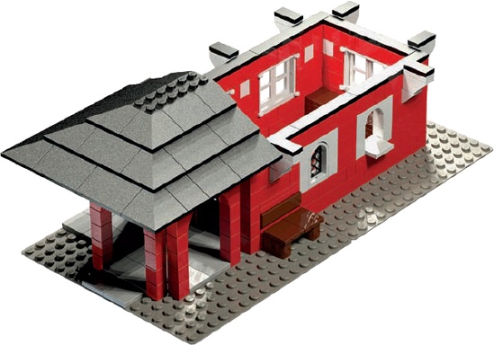
Figure 3-16 shows the completed main model. Next we’ll build the submodel that will help complete the main building.

A submodel is a group of pieces assembled separately from the main model. For example, the wings of an airplane might be a submodel of the airplane body, or the engine might be a submodel of a car. Once you complete the car’s body, you add the submodel (the engine). In the case of the train station, I’ll build the larger section of the roof as a removable submodel; one that will allow you to access the inside of the building by pulling off part of the roof.
Sometimes you’ll build submodels to simplify the construction of more complicated models, like a car engine. It’s easier to construct all of the little pieces for an engine outside the car, as submodels, and then place them into the main model. Other times, as in the roof, it can help to build separate, self-contained submodels to allow you access to your finished model or to make it easier to take it apart for transport.
The roof submodel is as wide as the portion of the roof we built earlier. It’s as long and as wide as the opening we left above the main part of the station, as you’ll remember from Figure 3-16. The roof submodel will match up perfectly with the main model, covering over the rest of the station to form a complete roof. At the same time, the roof submodel can easily be pulled off, letting you interact with the interior of the station.
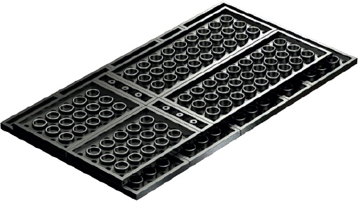
As you can see in Figure 3-17, I started with some plates facing studs down.

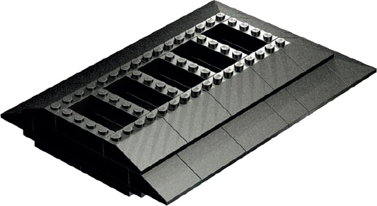
In Figure 3-18, you can see the placement of the next course of plates. (If I had put these plates down first, it would have been trickier to show how to position the next layer.)
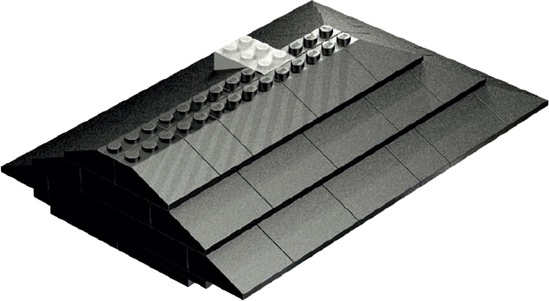
Once the first two steps are complete, it’s time to turn the plates right side up. In Figure 3-19, you can see that I began adding the slopes to form the angled part of the roof.

Figure 3-19. Flip the plates over, and then add slopes around the edges. The 1×8 bricks in the middle set the stage for the next layer.
Notice that I’m planning ahead here: I’m thinking of the next layer of slopes and how they will overlap the bottom layer of slopes and connect to the 1×8 bricks running through the middle to add strength to the model. These 1×8s provide another form of bracing.
In Figure 3-20, I added a second layer of roof bricks. I’m using the 1×4 standard bricks in the middle as the 1×8s below them are used: as a support system for the layer to come above them.
In successful LEGO models every layer or substructure works together to produce the final result. For example, in Figure 3-21, you see a 2×3 brick that seems to stick out from the slope bricks in the layer. This isn’t a mistake; it sets the stage for pieces I’ll add next.
Figure 3-22 shows why I added that 2×3 brick in the previous step: It’s become a solid platform for the remainder of the chimney. The peak elements added here cover up part of the 2×3 brick and make it look like it’s rising from inside the building, just like a real chimney would.
Now you’re ready to put this roof section onto the rest of the model. Gravity alone will hold it on; just place it gently on top of the open section of the train station. The result should look like Figure 3-3.

What if you want to build a railway station like mine, but you don’t have all of the pieces? No problem! You can replace certain pieces with more common ones, a design technique known as substitution.
Substitution has nothing to do with replacing French fries with mashed potatoes, but it has everything to do with making the best use of your existing LEGO pieces. I’ll show you a few examples of substitution in the following sections.
Even if your collection comes mostly from assorted buckets, you should have enough basic bricks to make the walls in the original station model design. You may not have exactly the right number of pieces in the same colors, so don’t be afraid to swap colors. Grey, brown, or even white would all be good color choices.
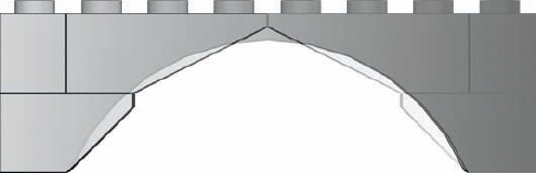
It’s often possible to build an arch from inverted slopes. To do this, you first need to determine the slope, or curvature, you’re trying to imitate. To get the right slope, you use a combination of the rise and the span.
The span is the length of a line that runs inside the arch, from edge to edge, as shown in Figure 3-23: The span and rise of an arch Figure 3-23. The rise (also shown) is the distance from this line to the inside center of the arch itself.

When you increase the span of your arch, you widen it, while at the same time dropping its relative height. By the same token, if you increase the rise of the arch, you’ll shrink its relative width, unless you increase its span. High, narrow arches are commonly found in doorways or as part of building facades.
Notice in Figure 3-24 that by carefully mixing different slopes, you can make some handsome arches without using a single arch brick. You could also insert standard bricks or plates between the layers of the slopes to increase the rise of the arch without affecting its span.
Sometimes you just don’t have enough of the right windows. Fortunately, some simple tricks can give your station its own characteristic windows. For example, in Figure 3-25 you can see that by simulating a small arch (replacing a 1×4 arch element), I’ve created a look similar to the original train station model in Figure 3-3.
To replace the windows on the sides of the station, try the trick shown in Figure 3-26. It’s not perfect, but it’s better than no windows at all.
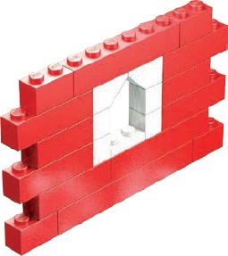
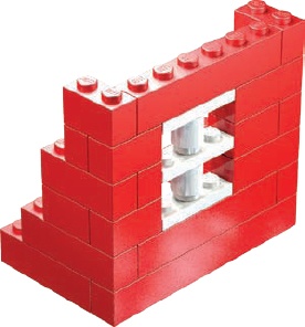
Figure 3-26. Substitutions usually won’t look exactly like the pieces they’re replacing, but searching for combinations that work is half the fun.
In Figure 3-26, I’ve put the thickness of a standard plate to good use: I’ve used three 1×3 plates separated by two 1×1 cylinders. The result is a window that is three bricks high and fits perfectly.
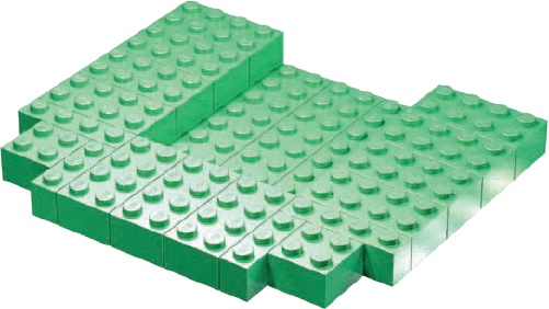
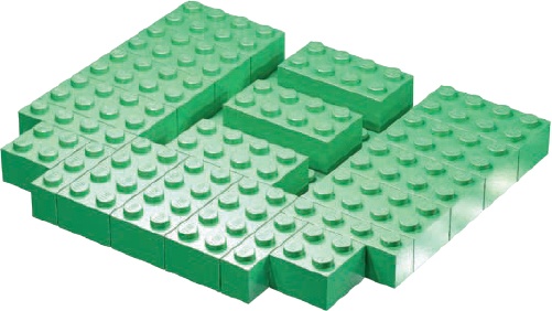
What if you need another way to create a roof? You know that color shouldn’t be an issue (if you don’t have any black sloped roof bricks, just use red or blue ones), but what if you don’t have enough slope bricks? You can use common 2×N bricks to create the illusion of a sloped (if somewhat jagged) roof, as shown in Figure 3-27 through Figure 3-32.
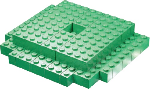
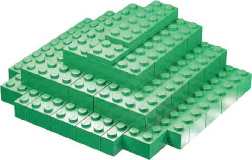
To create a substitute roof, begin by setting down a layer of bricks about the same length and width of the sloped roof. Next, add the second layer, overlapping any point where two lower-level bricks connect, as shown in Figure 3-30. By moving each layer inward by two studs, you can closely simulate the slope we created with the 33-degree roof bricks. Yet another effective use of both overlapping and staggering techniques.
You can use this technique to replace the steps shown in Figure 3-11 through Figure 3-16.
Figure 3-27. These are the same plates you see in Step 7 of the main model (Figure 3-11). Begin building your substitute roof from that point forward.

You can also create the roof submodel (as detailed in Figure 3-17 through Figure 3-22) using this same technique.
Our train station model has helped demonstrate some very basic building techniques at minifig scale. You’ve learned how to apply the overlap technique (Chapter 2), one that you’ll use often when you build. Although stacking and staggering are important, overlap generally creates the strongest bonds between LEGO elements.
You’ve also learned about substitution. Although the substitute roofs, windows, and arches don’t look quite as realistic as the “official” version, knowing how to substitute will offer you a lot of building flexibility. While a proper arch brick can only be a certain size and shape, your slope-derived versions can grow or shrink to suit your needs. So although the improvised version of the train station might not win awards for its looks, you can still use it to add character to a LEGO town with just the bricks you have at hand.
Remember that substitution isn’t a single technique. It’s a way of looking at a model and finding alternative ways to build it using the parts you have available. The LEGO system is remarkably flexible, and as long as you apply your creative abilities, you’ll never be stuck with just one way of doing things or just one particular element that you need to use.