Failure Modes and Effects Analysis
Abstract
In general, despite high quality control exerted, any product may have inherent weaknesses resulting in their failure. Instead of analyzing why the failures have occurred as a postmortem, we should always anticipate such failures and provide for their corrective action during the design stage itself. This is the principle behind failure modes and effects analysis and this chapter details several aspects, including the principles and procedures for this essential TQM tool.
Keywords
Before the event action; History of FMEA development; Apollo Space program; Pinto car project; Advanced product quality planning; Automotive industry action group; Design review based on failure mode; Concept FMEA; FRACAS; Design FMEA; Process FMEA; Service FMEA; Software FMEA; Failure mode; Failure causes; Failure effect; Severity factor; Probability of occurrence; Ease of detection; Risk priority number; FMEA procedure; Functional block diagrams; Fail safe measures; Responsibility of action
26.1 Uncertainties During Development
Every product or project undertaken by the engineer is an experiment because each stage of the design or development is experienced for the first time. There are uncertainties at every stage, and the engineer is bound to make presumptions, either from data, books, or from his experience. These uncertainties can be in the form of:
• models used for the design calculations,
• performance characteristics of the materials,
• inconsistencies in the materials purchased,
• nature of the pressure the finished product will encounter,
• size of the product, whether a medium-sized product or a large-sized product,
• volume of production, viz, batch production or mass production,
• specialized materials and skills used in the manufacture.
Apart from the above, the engineer may also experience uncertainties from the viewpoint of several other variables in the development.
26.2 Failure Modes and Effects Analysis
Failure mode and effects analysis (FMEA) is one of the best management tools to analyze the potential failure modes within a system under conditions of uncertainties, as stated above. Its principle is quite basic, and has been practiced since the olden days as the trial and error method. But since learning from each failure is both costly and time-consuming, the modern form of FMEA was developed during the 1940s, as explained in the following section. It emphasizes the probability of occurrence of that failure, and the severity of its effect on the system of every uncertainty. It is used to identify potential failure modes, determine their effect on the operation of the product, and identify actions to mitigate the failures. It analyzes potential reliability problems early in the development cycle, where it is easier to take actions to overcome these issues, thereby, enhancing reliability through design. FMEA should always be done whenever failures would mean potential harm or injury to the user of the end item being designed. According to Besterfield et al., FMEA is a “before-the-event” action requiring a team effort to easily and inexpensively alleviate changes in design and production. It is widely used in manufacturing industries in various phases of the product lifecycle and is now being applied in the service industry, too.
26.3 History of the Development of FMEA
• FMEA has its origin during the late 1940s for military usage by the US Armed Forces. This is incorporated in the military document MIL-P-1629, dated November 9, 1949, titled Procedures for Performing a Failure Mode, Effects, and Criticality Analysis, and subsequently ratified as MIL-STD-1629A.
• Its effectiveness in identifying and reducing any unseen problems encouraged its application for space research and design, specifically in the Apollo Space program and in developing the means to put a man on the moon and return him safely to earth.
• Its industrial application came during the early 1970s when the Ford Motor Company, reeling after the failure of its Pinto car project, introduced FMEA to the automotive industry to improve design, and for safety and regulatory considerations. SAE have documented this as SAE J 1739.
• FMEA methodology is now extensively used in a variety of industries, including semiconductor processing, food service, plastics, software, and healthcare.
• It is integrated into advanced product quality planning (APQP) to provide primary risk mitigation tools and timing in the prevention strategy, in both design and process formats.
• The automotive industry action group requires the use of FMEA in the automotive APQP process and published a detailed manual on how to apply the method. Each potential cause must be considered for its effect on the product or process and, based on the risk, actions are determined and risks revisited after actions are complete.
• Toyota has taken this one step further with its design review based on failure mode (DRBFM) approach. The method is now supported by the American Society for Quality, which provides detailed guides on applying the method.
• The Aerospace industry uses the term “Failure Modes, Effects and Criticality Analysis” (FMECA), to highlight the criticality factor in the application of FMEA is followed by Criticality analysis by which each potential failure is ranked according to the combined influence of severity and probability of occurrence. It identifies single point failures and ranks each failure according to a severity classification of failure effect, helping to identify weak links of design.
• Failure reporting and corrective action system (FRACAS) is another important component of FMEA.
26.4 Multiple Causes and Effects Involved in FMEA
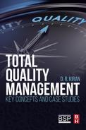
Most real systems do not follow the simple cause and effect model. As explained in the tree diagrams, a single cause may have multiple effects, and a combination of causes may lead to a single or multiple effects. This can also be represented in Fig. 26.1.
26.5 Types of FMEA’s
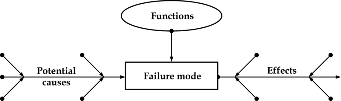
There can be several forms of FMEA based on which aspect of the activity is analyzed, and can be illustrated as per Fig. 26.2. Other forms of FMEA like System or Service can be interpolated into this illustration.
Concept FMEA (CFMEA)
• The concept FMEA is used to analyze concepts in the early stages before the component is defined (most often at system and subsystem level).
• It focuses on potential failure modes associated with the proposed functions of a concept proposal.
• This type of FMEA includes the interaction of multiple systems and interaction between the elements of a system at the concept stages.
Design FMEA (DFMEA)
• The design FMEA is used to analyze products before they are released to production.
• It focuses on potential failure modes of products caused by design deficiencies.
• Design FMEAs are normally done at three levels—system, subsystem, and component levels.
• This type of FMEA is used to analyze hardware, functions, or a combination.
Process FMEA (PFMEA)
• The process FMEA analyzes the potential failure modes within the process to identify the severity and frequency, based on past experience with similar processes, enables us to design these failures away from the process system with minimum effort and resource expenditure.
• The process FMEA is normally used to analyze manufacturing and assembly processes at the system, subsystem, or component levels.
• This type of FMEA focuses on potential failure modes of the process that are caused by manufacturing or assembly process deficiencies.
Other forms of FMEA can be
• System FMEA, which focuses on global system functions.
• Service FMEA, which focuses on service functions.
• Software FMEA, which focuses on software functions.
• Design Review Based on Failure Mode (DRBFM), a term coined by Toyota Motor Corporation, as an extension to DFMEA.
26.6 When to Use FMEA
• Whenever a new product or process is being initiated.
• Whenever changes are made to the product design, process, or the operating conditions. The product and process are interrelated. When the product design is changed, the process is affected and vice-versa.
• Whenever new regulations are being incorporated.
• When the customer feedback indicates problems in the product or process.
26.7 Basic Terms of Reference in FMEA
26.7.1 Failure Mode
The manner by which a failure occurs and is observed, for example, electrical short-circuiting, corrosion, cracking, or deformation. It may be noted that a failure mode in one component can lead to another failure mode in the same, or another component. Therefore, each failure mode should be listed in technical terms and also giving due consideration for their interrelations. IEC 812-1985 enumerates the generic failure modes as below:
| 1. | Structural failure (rupture) | 17. | Restricted flow |
| 2. | Physical binding or jamming | 18. | False actuation |
| 3. | Vibration | 19. | Failing to stop |
| 4. | Failing to remain in position | 20. | Failing to start |
| 5. | Eccentric rotation | 21. | Failing to switch |
| 6. | Failed interlocking system | 22. | Premature operation |
| 7. | Failing to open | 23. | Delayed operations |
| 8. | Failing to close | 24. | Erroneous input (increased) |
| 9. | Internal leakage | 25. | Erroneous input (decreased) |
| 10. | External leakage | 26. | Erroneous output (increased) |
| 11. | Fails out of tolerance (high) | 27. | Erroneous output (decreased) |
| 12. | Fails out of tolerance (low) | 28. | Loss of input |
| 13. | Inadvertent operation | 29. | Loss of output |
| 14. | Intermittent operation | 30. | Shorted (electrical) |
| 15. | Erratic operation | 31. | Open (electrical) |
| 16. | Erroneous indication | 32. | Leakage (electrical) |
| 33. | Other unique failure conditions as applicable to the system characteristics, requirements, and operational constraints | ||

26.7.2 Failure Cause
The product or process defects or any other quality imperfections would initiate further deterioration leading to a failure. Some failure modes may have more than one cause or mechanism of failure and each of these shall be listed and analyzed separately.
26.7.3 Failure Effect
Failure effect is the immediate consequences of a failure on operation, function or functionality, or status generally, as perceived or experience by the user. Some of the effects can be cited as, injury to the user, inoperability of the product or process, deterioration in product quality, nonadherence to the specifications, emanation of odors, noise, etc. Also the effect of this failure on other systems in immediate contact with the system that failed has to be considered. If a component fractures, it may cause vibration in the subsystem that is in contact with the fractured part. FMEA is the technique used in analyzing the potential failures and their effect on the system.
26.7.4 Severity Factor
A symbolic measure of the failure effect is the severity factor, which is the assessment of the seriousness of the effect of the potential failure. It is noteworthy that the severity represents the seriousness of the failure and not the mode of the failure. Besterfield emphasizes in this connection that no single list of severity criteria is applicable to all designs, and the team should agree on evaluation criteria and on a ranking system that are consistent throughout the analysis. The severity of the effect is given a severity number (S) from 1 (no danger) to 10 (critical), as given in Table 26.1.
Table 26.1
Rankings of Severity of Effect
| Effect | Severity of Effect | Severity Factor |
| Hazardous without warning | Very high ranking with potential failure mode affects safe operation and regulation noncompliance. Failure occurs without warning. | 10 |
| Hazardous with warning | Very high ranking with potential failure mode affects safe operation and regulation noncompliance. Failure occurs with warning. | 9 |
| Very high | Hazardous. Even if the component does not fracture, it becomes inoperable. | 8 |
| High | Item is operable, but with loss of performance. Customer is dissatisfied. | 7 |
| Moderate | Product is operable but with loss to comfort/convenience. Customer experiences discomfort. | 6 |
| Low | Product is operable, but with loss to comfort/convenience. Customer has some discomfort. | 5 |
| Very low | Certain item characteristics do not conform to specifications, but noticed by most customers. | 4 |
| Minor | Certain item characteristics do not conform to specifications, but noticed by average customers. | 3 |
| Very minor | Certain item characteristics do not conform to specifications, but noticed by some discriminating buyers (referred to as dissatisfies in Chapter 3). | 2 |
| None | No effect | 1 |
26.7.5 Probability of Occurrence
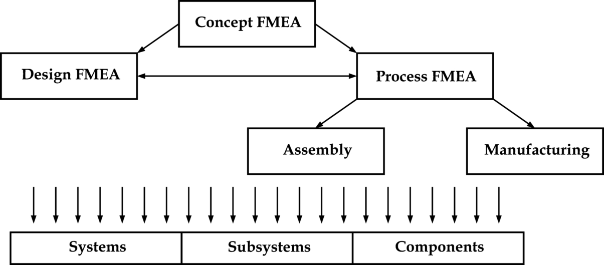
Probability of occurrence is the chance that one of the specific failure causes will occur. This recoding of probability of occurrence must be done for every cause indicating the probability of occurrence of that cause. This can be done by looking at the occurrence of failures for similar products or processes, and the failures that have been documented for them in technical terms. For FMEA, such an occurrence rate can be assigned a numerical value from 1 to 10, the least frequent being 1 and the most frequent being 10 (Table 26.2). If this value is more than 4, it implies that the actions needed to identify and analyze them shall be more meticulous. Besterfield et al. suggest the following guideline questions for evaluation.
Table 26.2
Rankings of Probability of Occurrence
| Probability of Occurrence | Explanation | Possible Failure Rate | Ranking No. |
| Very high | Failure is almost inevitable | > 1 in 2 | 10 |
| 1 in 3 | 9 | ||
| High | Generally associated with processes similar to previous processes that have often failed | 1 in 8 | 8 |
| 1 in 20 | 7 | ||
| Moderate | Generally associated with processes similar to previous processes that have experienced occasional failures | 1 in 80 | 6 |
| 1 in 400 | 5 | ||
| 1 in 2000 | 4 | ||
| Low | Isolated failures associated with similar processes | 1 in 15,000 | 3 |
| Very low | Only isolated failures associated with almost identical processes | 1 in 150,000 | 2 |
| Remote | Failure is unlikely. No failures ever associated with almost identical processes | < 1 in 1,500,000 | 1 |
• What is the service history or field experience with similar systems or subsystems?
• Is the component similar to a previous system or subsystem?
• How significant are the changes in the component is a new model?
• Is the component completely new?
• Is the component application any different form the previous?
• Is the component environment any different than before?
26.7.6 Ease of Detection
This is the ability of the inspecting mechanism and/or design control to detect the potential cause or the subsequent failure mode before the component or the subsystem is completed for production. The proper inspection methods need to be chosen. First, an engineer should look at the current controls of the system that prevent failure modes from occurring, or which detect the failure before it reaches the customer. Hereafter, one should identify testing, analysis, monitoring, and other techniques that can be or have been used on similar systems to detect failures. From these controls, an engineer can learn how likely it is for a failure to be identified or detected. This parameter, too, is given a numerical value between 1 and 10, called the Detection Rating (Table 26.3). This ranking measures the risk that the failure will escape detection. A high detection number indicates that the chances are high that the failure will escape detection.
Table 26.3
Rankings of Ease of Detection
| Ease of Detection | Explanation | Ranking No. |
| Absolutely impossible | No known controls available for detection of the failure mode | 10 |
| Very remote | Very remote likelihood that the current controls will detect failure mode | 9 |
| Remote | Remote likelihood that the current controls will detect failure mode | 8 |
| Very low | Low remote likelihood that the current controls will detect failure mode | 7 |
| Low | Low remote likelihood that the current controls will detect failure mode | 6 |
| Moderate | Moderate remote likelihood that the current controls will detect failure mode | 5 |
| Moderately high | Moderately high remote likelihood that the current controls will detect failure mode | 4 |
| High | High remote likelihood that the current controls will detect failure mode | 3 |
| Very high | Very high remote likelihood that the current controls will detect failure mode | 2 |
| Almost certain | Reliable controls are known with similar processes and currant controls almost certain to detect the failure mode | 1 |
Other terminology used in FEMA:
• Indenture levels: An identifier for item complexity. Complexity increases as levels are closer to one.
• Local effect: The failure effect as it applies to the item under analysis.
• Next higher level effect: The failure effect as it applies at the next higher indenture level.
• End effect: The failure effect at the highest indenture level or total system.
26.8 Risk Priority Number
Risk priority number (RPN) is a function of the three parameters discussed above, viz, the severity of the effect of failure, the probability of occurrence, and the ease of detection for each failure mode. RPN is calculated by multiplying these three numbers as per the formula below,
where S is the severity of the effect of failure, P is the probability of failure, and D is the ease of detection.
RPN may not play an important role in the choice of an action against failure modes, but will help in indicating the threshold values for determining the areas of greatest concentration. In other words, a failure mode with a high RPN number should be given the highest priority in the analysis and corrective action. The relationship between the above mentioned parameters of FEMA may be represented as in Fig. 26.3.

26.9 Procedure for FMEA
In principle, the causes or the specific faults are described in terms of those that can be detected and controlled. Action taken generally should result in a lower severity, lower occurrence, or higher detection rating by adding validation and verification controls
2. Identify the failure modes.
3. Identify the effects of the failure modes.
4. Determine the probability of occurrence (see Table 12.2).
5. Determine the severity of occurrence (see Table 12.3).
6. Apply this procedure for potential consequences.
7. Identify possible causes.
8. Identify the root cause.
9. Calculate the criticality.
10. Identify special characteristics.
11. Assess the probability that the proposed system detects the potential weaknesses.
Princeton Plasma Physics Laboratory suggests the following basic steps for FMEA:
1. Define the system and its functional and operating requirements;
a. Include primary and secondary functions, expected performance, system constraints, and explicit conditions that constitute a failure. The system definition should also define each mode of operation and its duration.
b. Address any relevant environmental factors, such as temperature, humidity, radiation, vibration, and pressure during operating and idle periods.
c. Consider failures that could lead to noncompliance with applicable regulatory requirements. For example, a failure that could result in a pollutant release that exceeds environmental permit limits.
2. Develop functional block diagrams showing the relationships among the elements and any interdependencies. Separate diagrams may be required for each operational mode. As a minimum, the block diagram should contain:
a. A breakdown of the system into major subsystems, including functional relationships;
b. Appropriately and consistently labeled inputs and outputs and subsystem identification;
c. Any redundancies, alternative signal paths, and other engineering features that provide “failsafe” measures.
Existing drawings developed for other purposes may be used for the FMEA if the above elements are adequately described.
3. Identify failure modes, their cause and effects.
a. IEC 812 1985 provides a list of failure modes, reproduced here as table in Section 26.7.1, to describe the failure of any system element.
b. Identify the possible causes associated with each postulated failure mode. The above list can be used to define both failure modes and failure causes. Thus, for example, a power supply may have a specific failure mode “loss of output” (29), and a failure cause “open (electrical)” (31).
c. Identify, evaluate, and record the consequences of each assumed failure mode on system, element operation, function, or status. Consider maintenance, personnel, and system objectives, as well as any effect on the next higher system level.
4. Identify failure detection and isolation provisions and methods. Determine if other failure modes would give an identical indication and whether separate detection methods are needed.
5. Identify design and operating provisions that prevent or reduce the effect of the failure mode. These may include:
a. Redundant items that allow continued operation if one or more elements fail;
b. Alternative means of operation;
c. Monitoring or alarm devices;
d. Any other means permitting effective operation or limiting damage.
6. Identify specific combinations of multiple failures to be considered. The more multiple failures considered, the more complex the FMEA becomes. In many such cases it would be advantageous to perform a FMECA using the guidance of IEC Standard 812 or MIL-STD-1629A. Using the FMECA, the severity of failure effects are categorized, the probability is determined, and the number of redundant mitigating features needed to keep the probability of failure acceptably low are better determined.
7. Revise or repeat, as appropriate, the FMEA as the design changes. Changes may be in direct response results of the previous FMEA or may be due to unrelated factors.
Kenneth Crow, on the website http://www.npd-solutions.com/fmea.html, suggests the following procedure for FMEA, which is quite similar to the above detailed procedure by Princeton Plasma Physics Laboratory, but is more exhaustive.
1. Describe the product/process and its function. An understanding of the product or process under consideration is important to have clearly articulated. This understanding simplifies the process of analysis by helping the engineer identify those product/process uses that fall within the intended function, and which ones fall outside. It is important to consider both intentional and unintentional uses because product failure often ends in litigation, which can be costly and time-consuming.
2. Create a block diagram of the product or process. A block diagram of the product/process should be developed. This diagram shows major components or process steps as blocks connected together by lines that indicate how the components or steps are related. The diagram shows the logical relationships of components and establishes a structure around which the FMEA can be developed. Establish a coding system to identify system elements. The block diagram should always be included with the FMEA form.
3. Complete the header on the FMEA form worksheet: Product/System, Subsys./Assy., Component, Design Lead, Prepared By, Date, Revision (letter or number), and Revision Date. Modify these headings as needed.
4. Use the diagram prepared above to begin listing items or functions. If items are components, list them in a logical manner under their subsystem/assembly, based on the block diagram.
5. Identify failure modes. A failure mode is defined as the manner in which a component, subsystem, system, process, etc., could potentially fail to meet the design intent. Examples of potential failure modes include:
b. Hydrogen embrittlement
c. Electrical short or open
d. Torque fatigue
e. Deformation
f. Cracking
6. A failure mode in one component can serve as the cause of a failure mode in another component. Each failure should be listed in technical terms. Failure modes should be listed for the function of each component or process step. At this point, the failure mode should be identified whether or not the failure is likely to occur. Looking at similar products or processes and the failures that have been documented for them is an excellent starting point.
7. Describe the effects of those failure modes. For each failure mode identified, the engineer should determine what the ultimate effect will be. A failure effect is defined as the result of a failure mode on the function of the product/process as perceived by the customer. They should be described in terms of what the customer might see or experience should the identified failure mode occur. Keep in mind the internal as well as the external customer. Examples of failure effects include:
b. Inoperability of the product or process
c. Improper appearance of the product or process
d. Odors
e. Degraded performance
f. Noise
Establish a numerical ranking for the severity of the effect. A common industry standard scale uses 1 to represent no effect and 10 to indicate very severe with failure affecting system operation and safety without warning. The intent of the ranking is to help the analyst determine whether a failure would be a minor nuisance or a catastrophic occurrence to the customer. This enables the engineer to prioritize the failures and address the real big issues first.
8. Identify the causes for each failure mode. A failure cause is defined as a design weakness that may result in a failure. The potential causes for each failure mode should be identified and documented. The causes should be listed in technical terms and not in terms of symptoms. Examples of potential causes include:
b. Improper operating conditions
c. Contamination
d. Erroneous algorithms
e. Improper alignment
f. Excessive loading
g. Excessive voltage
9. Enter the probability factor. A numerical weight should be assigned to each cause that indicates how likely that cause is (probability of the cause occurring). A common industry standard scale uses 1 to represent not likely and 10 to indicate inevitable.
10. Identify current controls (design or process). Current controls (design or process) are the mechanisms that prevent the cause of the failure mode from occurring or which detect the failure before it reaches the customer. The engineer should now identify testing, analysis, monitoring, and other techniques that can or have been used on the same or similar products/processes to detect failures. Each of these controls should be assessed to determine how well it is expected to identify or detect failure modes. After a new product or process has been in use, previously undetected or unidentified failure modes may appear. The FMEA should then be updated and plans made to address those failures to eliminate them from the product/process.
11. Determine the likelihood of detection. Detection is an assessment of the likelihood that the current controls (design and process) will detect the cause of the failure mode or the failure mode itself, thus preventing it from reaching the customer.
12. Review RPNs. The RPN is a mathematical product of the numerical severity, probability, and detection ratings: RPN = (severity) × (probability) × (detection)
The RPN is used to prioritize items than require additional quality planning or action.
13. Determine recommended action(s) to address potential failures that have a high RPN. These actions could include specific inspection, testing or quality procedures; selection of different components or materials; de-rating; limiting environmental stresses or operating range; redesign of the item to avoid the failure mode; monitoring mechanisms; performing preventative maintenance; and inclusion of back-up systems or redundancy.
14. Assign responsibility and a target completion date for these actions. This makes responsibility clear-cut and facilitates tracking.
15. Indicate actions taken. After these actions have been taken, re-assess the severity, probability, and detection and review the revised RPNs. Are any further actions required?
16. Update the FMEA as the design or process changes, the assessment changes or new information becomes known.
26.10 Responsibility for Action
FMEA is a team operation. Everyone should feel fully involved in the process and in moving towards the goal. Nevertheless, it is always advisable to delegate certain responsibilities to specified persons, so that the monitoring and reporting can be effective. It is suggested that some of the responsibilities be allocated between the line manager, the analyst, and the reviewer as follows:
Line manager
1. Assign individuals to perform FMEA (analyst) and another individual to review it (reviewer). The reviewer shall have as much expertise and technical experience as the analyst.
Analyst
2. Describe the system under analysis, prepare system diagrams, and use existing documentation to depict all major components and their performance criteria. The level of assembly may vary with the level of the analysis.
3. Perform FMEA as per the procedure described earlier.
4. Sign FMEA and provide it to the reviewer.
Reviewer
5. Review FMEA for technical content and sign if no significant problems are identified. Otherwise discuss the FMEA with the analyst.
6. Ensure that the full FMEA documents are filed in the Operations Center.
26.11 Benefits of FMEA
• Effective prevention planning program
• Identification of change requirements
• Cost reduction
• Increased throughput
• Decreased waste
• Decreased warranty costs
• Reduction of nonvalue added operations
• Improvement in the quality, reliability and safety of a product/process
• Improvement in company image and competitiveness
• Increased user satisfaction
• Reduced system development timing and cost
• Data collection (expert systems) for reduced future failures.
• Reduce warranty concerns
• Early identification and elimination of potential failure modes
• Minimal late changes and associated cost
• Catalyst for teamwork and idea exchange between functions
• Reduction in the possibility of same kind of failure in future
While the general benefits of FMEA can be listed as above, the category-wise benefits can be summarized as under:
Concept FMEA
• Helps selecting the optimum concept alternatives, or determine changes to design specifications.
• Identifies potential failure modes caused by interactions within the concept.
• Increases the likelihood all potential effects of a proposed concept’s failure modes are considered.
• Identifies system level testing requirements.
• Helps determine of hardware system redundancy may be required within a design proposal.
Design FMEA
• Aids in the objective evaluation of design requirements and design alternatives.
• Aids in the initial design for manufacturing and assembly requirements.
• Increases the probability that potential failure modes and their effects have been considered in the design/development process.
• Provides additional information to help plan thorough and efficient test programs.
• Develops a list of potential failure modes ranked according to their effect on the customer. Establishes a priority system for design improvements.
• Provides an open issue format for recommending and tracking risk reducing actions.
• Provides future reference to aid in analyzing field concerns.
Process FMEA
• Identifies potential product-related process failure modes.
• Assesses the potential customer effects of the failures.
• Identifies the potential manufacturing or assembly process causes and identifies process variables on which to focus controls or monitoring.
• Develops a ranked list of potential failure modes, establishing a priority system for corrective action considerations.
• Documents the results of the manufacturing or assembly process.
• Identifies process deficiencies.
• Identifies confirmed critical characteristics and/or significant characteristics.
• Identifies operator safety concerns.
• Feeds information on design changes required and manufacturing feasibility back to the designers.
26.12 FMEA Software
The following software have been developed for industrial and dedicated application as per information available in internet. It may be remembered that FMEA software refers to the software available for FMEA solutions, whereas Software FMEA refers to the process of applying FMEA so solve problems in software development.
1. ASENT FMEA Software—Raytheon’s premiere reliability and maintainability tool suite. Includes a very powerful FMECA tool that combines FMECA, RCM analysis, and testability analysis.
2. Byteworx—Powerful, cost-effective software for FMEA. It is the global choice of the Ford Motor Company. Byteworx FMEA is fully compliant with SAE J-1739 Third Edition.
3. FMEA-Pro—FMEA/FMECA software from Dyadem. An all-in-one software solution provides corporate consistency and assists with corporate compliance.
4. Isograph Software—Their Reliability Workbench contains a FMEA/FMECA tool.
5. Item Software—FMEA/FMECA/FMEDA—Failure Mode Effects Analysis tool.
6. Quality Plus—FMEA software from Harpco Systems, Inc. Performs both Design and Process FMEAs.
7. RAM Commander Software—ALD’s integrated FMEA/FMECA modules have been adopted by many civil, military, aerospace, energy and pharmaceutical organizations worldwide.
8. Relex Software—Offers FMEA tools and FMEA software to process FMEA and meet all functional FMEA standards for criticality matrix.
9. XFMEA—FMEA software from ReliaSoft. Provides expert support for all types of FMEA.
26.13 Conclusion
As seen in this chapter, FMEA helps us in anticipating unexpected failures and providing for their corrective action during the design stage itself. Right from the days of its conception in the 1940s, it has today become a must for the designers.
