
8
Communication Architectures and Technologies for Advanced Smart Grid Services
Francois Lemercier1, Guillaume Habault2, Georgios Z. Papadopoulos2 Patrick Maille2, Nicolas Montavont2 and Periklis Chatzimisios3
1 Itron and IMT Atlantique ‐ IRISA, 2 rue de la Chataigneraie, 35510 Cesson‐Sévigné, France
2 IMT Atlantique ‐ IRISA, 2 rue de la Chataigneraie, 35510 Cesson‐Sévigné, France
3 Department of Informatics, Alexander T.E.I. of Thessaloniki PC 57400, Sindos, Thessaloniki, Greece
8.1 Introduction
Over the past years, the demand for electricity has faced a drastic growth, as the number and heterogeneity of electrical devices is continuously increasing. In parallel, the power sector is undergoing major changes, mostly by the switch from fossil to renewable energies, the evolving energy policies, and the emergence of less reliable renewable micro‐generation. As stated in a 2015 Eurelectric survey [1], the grid requires taking into consideration these modifications while ensuring secure, sustainable, competitive, and affordable energy for any individual and business.
Proper operation of the electrical network is based on the balance between production and consumption, a great challenge for the network management. Actually, the grid structure is evolving from a rigid and centralized architecture with large production units at the top satisfying demand at the bottom to a more distributed one with individual premises equipped with local renewable production units. Electrical production is therefore getting more decentralized but at the same time less predictable as renewable sources are sporadic. In order to efficiently balance production and consumption, real‐time measurements, predictions, and control capabilities are needed in a widespread management system.
Furthermore, electrical devices have also evolved in recent years. Some are now mobile such as electric vehicles (EVs) making demand prediction more difficult; others, such as connected heating/cooling devices, offer remote management capabilities to their owners. Together, their growing numbers, and in particular the increasing penetration of EVs, make the management of the system even more complex. Today, private EVs are charged as soon as they are plugged into the grid, without any management system. And most of these charging processes occur at peak hours, in the evening, which is very challenging for the grid. While there are only few EVs, the electrical grid can afford to provide this power. But if EVs are generalized, we will need to avoid charging all of them on peak hours and so, shift these demands on a time window that will contain the needed power below a given threshold and/or align the consumption to the production periods. As a consequence, it is vital for the smart grid to benefit from a control system of the charging periods to balance the various energy demands over different periods of time. As presented by Lefrancois et al. [2], several mechanisms are required to provide smart‐charging services in an automated way. Moreover, EVs can be seen as mobile batteries from the electrical network. In order to integrate such devices into the system, mobility mechanisms are needed. Therefore, with appropriate ICT systems and services – such as smart charging ones – the smart grid could be able to efficiently use these batteries. For instance, the electrical grid could encourage them to charge at given periods – and compensate for overproduction – or it could ask them to re‐inject their electricity when and where it is needed [3].
Nevertheless, electrical devices, such as EVs or home appliances, are not components of the smart grid yet. Their presences and types depend on users' will. Even though utilities could benefit from managing these devices, the complexity arising from them is out of their scopes [4]. As a consequence, a smarter and extended grid is required more than ever to support utilities efficiently, monitor, and manage this system [5], as well as “connecting” the grid with devices beyond.
The ongoing transition in the energy sector has propelled innovation forward. The electrical grid is already getting smarter: it enables both automated meter reading and indirect controlling demand with real‐time pricing signals. Under a smarter system, new business opportunities can be envisioned. Indeed, a system offering optimized and automated energy production, distribution, and consumption will enable the appearance of flexible services (selling flexibility in consumption or production). Together with appropriate incentives, this would lead to the creation of new energy markets that would take place at various scales and levels.
These objectives can only be accomplished with a proper ICT architecture to first interconnect all energy actors. As long as this interconnection is ensured, they will be able to exchange energy information (consumption, production, or storage) and use available energy services. Such an architecture must address several requirements. First, it has to take into consideration the diversity of electrical devices that are plugged into the grid. The architecture must be flexible enough to adapt to different hardware constraints and software choices and absorb their evolution over time. Scalability is another must for the architecture, since the future smart grid involves a huge number of devices, including consumption devices and production sites. Finally, real‐time measurements, prediction, and control capabilities are required to better plan for the production and consumption alignment. Consequently, the architecture must provide efficient mechanisms to 1) collect and process all the produced data; and 2) make decisions and control end points accordingly. Note that some actors might not require data in real time, nor detailed data (ensuring data privacy). Lastly, it must be secured in order to avoid any entity both taking control of a device without being authorized and collecting data without being granted access to it.
There are also several issues to solve before implementing such an innovative system. While the remote control and coordination for electrical loads of homes, office buildings, and industrial premises have been possible for decades, such control is not yet widely enough adopted as it involves handling the issue of control of a large volume of distributed nodes. Furthermore, such a system should deal with the challenges of new electrical networks in which any party can act as an energy producer and/or consumer; hence the term “prosumer.” These challenges require to deal with the following issues:
- finding a given party in a large structure;
- accessing a given resource (data or control of nodes);
- incentivizing for this access; and
- implementing technical compatibility with any system.
To properly cope with these problems, ICT is needed for energy actors to interconnect and better manage energy usage. Future smart grid systems should provide the tools for an efficient integration of the following:
- local renewable energy production;
- management systems to retrieve electrical production, consumption, and storage information; and
- other energy actors to provide systems, mechanisms, or services that use such information for electricity management and control.
In order to achieve these goals, technology is required to:
- offer automated access to any measurement point and load, in order to lower the cost of control; and
- exchange data in such a way that it will allow data availability for large‐scale scenarios as well as to make possible application‐specific extensions in order to realize the management of heterogeneous infrastructures.
In this chapter, we focus on presenting communication architectures, technologies, and protocols employed in the smart grid environment to solve the problems that a balancing system must face. In Section 8.2 we provide an overview of the existing communication systems currently utilized in the smart grid, and then we present what is required in order to meet a next‐generation smart grid system. Before concluding, Section 8.3 develops the routing issues and certain existing solutions to efficiently transmit information while using constrained technologies.
8.2 The Smart Grid Communication Architecture and Infrastructure
In smart grids, the legacy communication architecture enabling data collection and device management is called the advanced metering infrastructure (AMI) [6, Chap. 7]. This architecture is an evolution of the automated meter reading (AMR) by adding a bidirectional communication framework, which was deployed to facilitate meter reading, billing, and consumption planning. This two‐way communication feature of AMI also offers additional operations on a network. It sure helps the utilities better control their network, but several other opportunities are foreseen with such architecture especially if using high‐speed Internet protocol (IP)‐based technologies.
In this section, we describe the AMI architecture that involves the main elements of the electric supply chain (smart meters, distribution units, production units). While AMI communications are operated by utilities and allow basic services such as monitoring and some control, we will show that they are not enough to provide the grid with fine‐grained and optimized capabilities such as appliance‐level demand‐response. For such advanced possibilities, we claim that other communication systems are needed and that the currently developing paradigm [7] of the Internet of Things (IoT) is an excellent candidate. Hence, we develop that view later in this section.
The IoT consists of a set of smart “things” that are able to connect to the Internet –directly or via a gateway – and feed other devices with their collected information (often referred to as big data due to their high volume). As long as these things can be uniquely identified and provide some empirical data on our environment –in this case, electric information (consumption, production, or even storage status)– anything can be a “thing.” But they may have different capabilities in terms of hardware and control (e.g., a sensor compared to an EV).
In smart grid communication systems, like other communication systems, we can distinguish a core part and a last‐mile1 part. The former involves large storage and computational capabilities used to collect, organize, and process data in order to coordinate devices through remote management commands. The latter part consists of uniquely identified and connected objects (e.g., sensors, actuators, and smart devices) as well as communication links between them, possibly by employing various wired or wireless technologies.
This section aims at detailing the characteristics and technologies of the different communication networks that comply with smart grid requirements. We here present the current state of advancement in this domain, as well as certain ongoing efforts to make the grid smarter.
8.2.1 DSO‐Based Communications
The legacy communication network used in smart grids is the aforementioned AMI. The main elements for such infrastructure are the so‐called smart meters, i.e., power meters embedded with communication capacities that are able to activate some generic functions from remote control. These meters are deployed by utilities and enable distribution system operators (DSOs) to both meter consumption and command end‐points remotely. This bidirectional communication helps DSOs efficiently manage their networks.
Hereafter, we describe the communication organization in such DSO‐based smart grids, as well as the limits that this structure imposes on the services that can be built.
8.2.1.1 The Existing AMI Organization
Energy distribution networks have a tree topology with large production units on top producing most of the required energy, which is then transported via a widespread distribution network toward consumers (called the end points). Figure 8.1 illustrates this top‐down configuration in which consumers can be reached after passing through different aggregating nodes, i.e., transformers. Utilities forecast the consumption of end points based on their historical consumption and adjust these forecasts based on automated metering. These forecasts are therefore very sensitive to any modification of end‐points behavior.
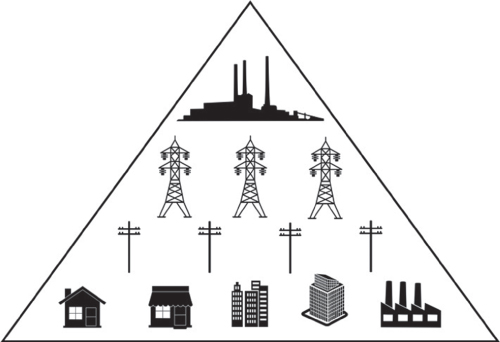
Figure 8.1 The current distribution network topology.
Currently there are several notable trends taking place in the energy market. Some examples are the shift away from fossil to renewable energy, the steadily increasing number and heterogeneity of electrical appliances and devices, and the decreasing price of various distributed energy production technologies.
DSOs require a bidirectional communication with smart meters in order to efficiently manage their networks and face these trends. In fact, one consequence of these upcoming changes is the growing demand at the consumer side. Therefore, utilities have to plan such growth, increase the amount of electricity produced, and transport this electricity toward the end points. However, as the distribution network capacity is limited, a question that arises is what will happen when reaching this limit. Utilities should encourage end points to balance their consumption during a 24 h period; hence the bidirectional communication with smart meters. In addition, consumers are getting more and more equipped with micro‐generation systems. As a consequence, the grid evolves toward a system in which large energy production facilities – dams, nuclear power plants, etc. – must coexist with a myriad of smaller, less reliable systems in the same network. Therefore, and without more information from these “prosumers” – at the same time consumer and producer – it will become more and more difficult for DSOs to estimate consumption of such end points. The ideal solution in order to take into consideration these trends would be to modify the whole distribution network. First, by increasing its capacity and secondly, by allowing prosumers to re‐inject their production excess into the network – and have smart meters metering it. However, these modifications are very costly and so inconceivable for now or should be planned and spread over several years. For these reasons, DSOs prefer to first set up means to efficiently meter as well as send signals to individuals to balance their consumption.
Therefore, initial smart grid efforts, mainly directed by DSOs, use the AMI in order to offer better management of a distributed energy production. And the smart meter is thus a central piece of the needed communication framework. On the one hand, it allows real‐time monitoring in order to collect accurate data about the consumption (and possibly the production). On the other hand, it allows receiving real‐time electricity pricing signals, which trigger a certain period of time where the energy is cheaper. Relays can be used in user premises to activate or deactivate devices that are plugged into a specific circuit (e.g., hot water tank, which could be switched on during the night).
As illustrated in Figure 8.2, the AMI consists of a tree of smart meters, placed at different positions of the network. Data from all these meters are collected, stored, processed, and analyzed by the utility center. Routing protocols are thus required from the smart meters (i.e., nodes of the tree) to the utility center (i.e., root of the tree) in order to forward the data hop by hop. Basic commands issued by the utility center to announce the price in real time are actually broadcast to the whole network and do not require unicast transmission.
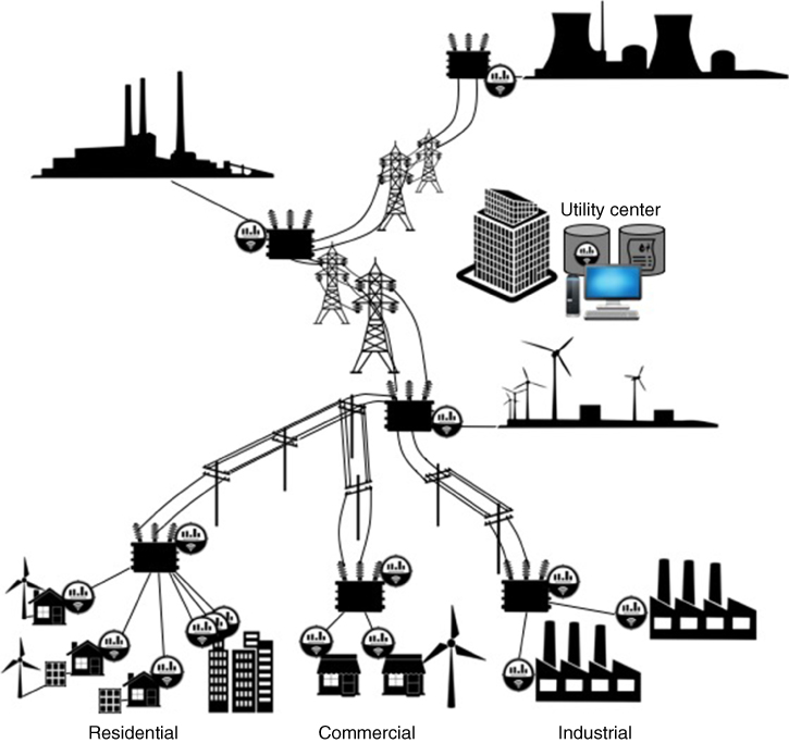
Figure 8.2 Illustration of an AMI.
8.2.1.2 Communication Technologies used in the AMI
Currently, the communication taking place within the core system is based on Internet technologies with IP above a variety of underlying technologies such as optical fiber, cellular network, or power line communication (PLC). With some of them, one aggregating node or a relay node can transfer data on behalf of hundreds of smart meters behind it. To reach the core of the AMI, data issued by (or intended to) the smart meters typically have different “hops” distance to perform. The distance to cover in one hop will vary depending on the network configuration. The technology used to communicate depends on this distance and the environment characteristics. In particular, the technologies used for the last‐hop heavily depend on a) the meter capabilities in terms of communication and processing power, b) the energy requirements for this communication, and c) the relative performance of the available options – such as the distance with a wireless base station, the quality of PLC transmission, etc. A non‐exhaustive list of commonly used technologies is given in Table 8.1, along with their advantages and drawbacks [8–10]. For wireless technologies, the “energy cost” column refers to the energy consumption associated with the technologies: it includes the transmission power, as well as the processing cost of the corresponding protocol stack and the specific medium access control procedures. The “monetary cost” reflects the cost of the hardware components needed to implement a technology, including SIM cards, as well as potential spectrum license fees.
Table 8.1 Communication technologies for the AMI last‐hop.
| Technology | Range | Throughput | Energy cost | Monetary cost |
| 802.15.4 [11, 12] | up to 100 m | up to 250 |
cheap | cheap |
| 802.11ah [8] | up to |
Tens of |
expensive | cheap |
| LoRaWAN [9] |
|
Tens of |
cheap | cheap |
| LTE‐Cat M [10] |
|
|
medium | expensive |
| Narrowband PLC [13] | several |
up to |
cheap | cheap |
| Wired Internet | – | up to |
cheap | expensive |
Table 8.2 LOADng / RPL comparison.
| Protocol | LOADng | RPL |
| Type | On‐Demand | Proactive |
| Algorithm | Distance Vector | Distance Vector Source Routing |
| Local repair | Yes | Yes |
| Mobility | Static, Mobile | Static, Mobile |
| Scalability | High | High |
| Supported traffic | P2P | P2P, P2MP, MP2P |
We need to bear in mind that all technologies listed in Table 8.1 are not always available: due to hardware limitations and/or environmental constraints, the choice can be limited.
8.2.1.3 AMI Limitations
Up to now, on the demand side, the smart grid is mostly limited to the smart meters. Their deployment within the AMI is mapped onto the distribution structure. Furthermore, the intelligence in meters or in intermediate nodes is very limited, leaving all the intelligence in the network core, i.e., the utility center. As a consequence, the AMI lies into a centralized system as previously illustrated: all the data transit through data centers controlled by a DSOs, where all storage and analysis actions are performed; in other words, the AMI is fully operated and controlled by utilities.
With respect to this status, we see three kinds of limitations, all in favor of the use of alternative communication systems.
First, we see issues in terms of incentives. Indeed, DSOs will not expect significant gains from improving the communication capabilities, since those gains will go to the entities exploiting them, such as flexibility operators. Conveying the data is not the core mission of DSOs, and they will probably be reluctant to invest in communication improvements if they do not get a return on investment.
Second, the current situation raises some privacy concerns: indeed, DSOs have now access to a precise electricity consumption over time, which may raise some privacy concerns. And, if the infrastructure evolves in a way that even more information is transferred to the DSO, e.g., with a per‐device monitoring, such a situation is unlikely to be accepted by users. On the contrary, they should decide which entity (if any) to trust with those data and at which granularity level.
Third, we envision some interoperability issues:
all the gathered data, which we recall are mainly used for billing and planning purposes, are very sensitive. Therefore, DSOs will not likely let users, other organizations, or entities manipulate them. Consequently, the AMI is currently a closed network where there is no interconnection with other systems and architectures – resulting in a situation where users can only visualize their data. This missing interconnection limits the possibilities to cross‐reference or use information coming from other systems. For instance, senior monitoring systems would be more accurate if health information could be crossed with electric information, and DSOs could benefit from having external information to better plan consumption or production.
Nevertheless, smart meters will probably embed more functionalities in the future, such as data storage and decision / management mechanisms. However, adding such capabilities will increase the cost to produce and deploy such meters. Therefore, DSOs will have to determine a business model that will push them into deploying such a costly new system. Although, this suggestion appears to be innovative, if there is not a significant gain for DSOs, these “smarter” smart meters will never be deployed.
8.2.2 Internet‐Based Architectures
As stated before, other communication networks used in the smart grid are centered on the Internet and, thus, employ various IoT standards. The main elements for such architecture are the smart appliances, i.e., devices and/or appliances embedded with communication capabilities, as well as actuators or sensors. These new connected devices are “deployed” – or should we say, sold – by manufacturers and enable a user to have controllable devices. This actually gives the users a better control and knowledge of their appliances behavior – i.e., consume, produce, or store. In addition, it offers additional flexibility for users to change the way that their devices behave.
In the future, a large number of these smart appliances [14] is expected to appear – consuming, storing, and/or producing energy. These smart appliances provide their energy information (consumption or production) along with controlling capabilities. These smart devices are usually connected to the Internet, and if not – probably due to specific constraints – they are still accessible via gateways. This enables users to remotely access, control, and/or monitor smart devices. For instance, almost all of them come with a monitoring/controlling mobile application.
Furthermore, as the main purpose of the Internet is to interconnect systems, connected devices have access to a plethora of services and information. As a result, these smart appliances can use the Internet to have access to external information such as weather information. Moreover, manufacturers can develop management services on top of the Internet for users that prefer to leave the management of their smart appliances to third parties. Such Internet‐based communication networks offer many possibilities for smart grid applications and very likely some we have not even thought of yet.
An example of smart grid services that can be deployed over such architecture is the automatic shedding of certain industrial loads during peak hours. In fact, with such system, an operator could sell the flexibility of a pool of non‐critical industrial load as adjustment energy reserve for the grid. As a result, on grid demand – for instance during peak hours–, this flexibility operator (FO) can switch off a set of its managed load in order to reduce the peak. This peak reduction enables utilities to save money – e.g., avoiding to buy external electricity – which in return pay the FO for its assistance. Internet‐based architecture enables a FO to aggregate industrial load from different places and thus, to manage a large portfolio of flexibility. It can be considered as a full win‐win scenario as industry will also get a share of the FO's remuneration while decreasing their electricity bill.
In an Internet‐based architecture, the core domain is the Internet with all the protocols and standards it provides. Communication within the core domain is therefore IP‐based just like in the AMI. Moreover, last‐mile communications also rely on IP within the local area network (LAN) – or home area network (HAN), premise area network (PAN), field area network (FAN), or even business or industrial area network (BAN) – or they might use gateways to connect to IP.
The universal nature of the Internet and the flexibility of the IP stack provide lots of opportunities. Such architecture enables any provider to offer various services toward smart appliances – that might not be directly related to energy – as well as enhancing smart grid possibilities.
8.2.2.1 IP‐Based Architecture Limitations
Energy and smart grids are potential application domains for IoT among others such as transportation, health care, or environmental monitoring. One issue of such an Internet‐based solution is that there are several ways to implement an architecture for an enhanced smart grid. In addition, there is not only one standard architecture, leading the standardization efforts to be scattered [15, 16]. Furthermore, energy‐related information is fragmented toward several standards and metrics, leading almost all smart appliances to be manufacturer specific. This diversity leads to a fragmented landscape of architecture models and isolated “silos” implementation . Interconnection of these silos is very difficult, if not impossible, as they often use their own architecture, models, and mechanisms – sometimes even between silos belonging to the same application domain.
Another concern with this type of solution is the lack of security around the deployed devices. Everything and everybody is now connected on the Internet, but not all of them are benevolent. In fact, as most IoT architectures are not mature enough, they do not include strong security mechanisms to protect underlying networks. As a result, connected devices are more and more targeted in order to break in private networks and user privacy2.
Last but not least, there is no actual interconnections with utilities networks apart from a potential interaction with the centralized management system in order to realize demand response (DR) mechanisms. Nevertheless, enabling crossed information from both smart meters and smart appliances could greatly enhance smart grid systems.
8.2.3 Next‐Generation Smart Grid Architecture
As mentioned in the previous sections, there are currently two types of smart grid systems, each using different types of communication technologies: 1) One relying on smart meters and mostly used by utilities; 2) The other one relying on smart appliances and mostly used by end users. However, each system has some drawbacks and would benefit from the other. The next‐generation grid communication network has a future that is all planned out. It is expected to interconnect both systems in order to provide an enhanced one as depicted in Figure 8.3. In this figure, each site has both a smart meter, an energy management system (EMS) (depicted as a gray server), along with Internet access. It receives information from the grid (solicitation or demand) via the smart meter (which is also used for billing). Each EMS aggregates data collected from both smart appliances and the smart meter in order for the end user to have an almost real‐time visualization of its consumption, production, and storage (if any). An EMS can also inform the grid of its capabilities (production, load shedding, etc.) via the smart meter. EMSs can operate collectively and depend on a “higher” EMS to form a microgrid – a smaller managed grid, as depicted by the gray cloud. This microgrid will also have its own EMS that will be able to coordinate “lower” ones in order to respond to the grid more efficiently and on a larger scale.
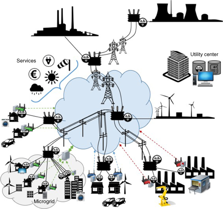
Figure 8.3 Illustration of the next‐generation smart grid system.
This next‐generation grid should involve more consumers and prosumers in the management decisions of their own sites. In order to optimize consumption and production both at the premises and on a global level, it is crucial to simultaneously utilize inputs from a) the grid, such as pricing and demand; b) the user, providing its needs and requirements; c) smart appliances, informing on their specificity and capabilities – e.g., shedding potential. Consequently, all these data are combined in order to determine the best usage for given smart appliances. Moreover, being connected to the Internet, this system will also have access to several services and information coming from non‐energy related connected objects (such as outside temperature, weather forecasts, etc.) that might also help in the decision making. Nevertheless, in order to reach such a complex system, several challenges need to be addressed.
8.2.3.1 Technical Issues for Next‐Generation Smart Grids
The number of smart objects is expected to explode in the near future [17]. Many of them will be electrical appliances, leveraging connectivity to provide daily‐life services to their owners and possibly to the grid (through load shedding or storage for instance). This plethora of smart devices will use different types of access technologies, protocols, and information formats. As a consequence, this next‐generation system should be flexible, adaptable, and dynamic and will enable automation.
In order to support scalability, this diversity of devices has to be handled locally. It will first lower the complexity of such system and then enable local management. However, smart meters currently deployed in the AMI have not been designed for managing and aggregating data on behalf of several appliances, nor for enabling such elaborated services – i.e., collecting input from users and from other devices/services in order to analyze data and control appliances.
8.2.3.2 Handing Back the Keys to the User: Energy Management Should Be Separated from the Smart Meter
We insist here on the distinction between the devices interacting with the user (to make decisions within its area) and the devices used by the utility to monitor and bill the area consumption, as well as inform about the grid demands.
In order to enable a more effective energy management, end users have to be more involved with respect to their data as well as to make decisions about energy usage. Their involvement should not anymore only be on a monitoring basis. They have to understand how they consume (and produce) and at the same time how they can act for both their own and the grid benefits. Therefore, they will be part of local decision making regarding the balance of their own consumption and production, and/or at the same time they could participate in the balance optimization of the whole grid by shifting, postponing, or switching off their appliances upon request. Therefore, the next‐generation smart grid architecture should provide users with the proper tools to control both their data and energy usage.
In order to realize all these actions, a dedicated management equipment is required. The smart meter could play this role if it can be equipped with new functionalities (storage, analysis, and user interactions). However, as previously mentioned, this will initially be more costly for the DSO and also implies that the user could possibly alter the functioning of the smart meter through interactions. Let us recall that the main purpose of smart meters is to ensure billing and planning for utilities; it is therefore not acceptable to affect the communications with the utility management center. For these reasons, it is very unlikely that the smart meter would act as a local EMS in the future.
On the contrary, it is more probable to see users acquiring an independent EMS in order to have access to energy services. Smart meters would still be in use, first by the DSO to monitor, bill, and send grid‐related requests (consumption reduction or increase, load shifting) and furthermore, by the EMS in order to be aware of the site global consumption and possibly to share certain data with the DSO (e.g., consumption forecast). In any case, the per‐device decisions should be left to the EMS, either directly operated by the user or by a specific service provider.
This may enable new open markets for energy management in which the users should be able to choose who will get access to their detailed energy data as well as control of their smart appliances. Similarly, the users should be free to decide whether to let a third party manage their consumption/production and if positive, to select one. Switching among “energy management service providers” should be simple enough so that market competition would lead to a desirable outcome.
8.2.3.3 To Build an Open Market, Use an Open Network
As previously stated, the communication network used for energy management should be adaptive, dynamic, flexible, and easily accessible to allow fair competition. The Internet naturally appears as a good candidate as it is built on open standards that provide almost all these features while adapting to smart grid applications through various IoT standardization efforts. The openness of the Internet and its standards seem preferable than letting energy operators define proprietary networks and protocols. The latter approach might potentially lead to several isolated platforms with few potential interconnections. With the use of the right tools, the Internet will provide all the required flexibility to handle a large volume of distributed consumption and production points.
As a result, the next‐generation smart grid core network should be decentralized and mainly focus on ensuring the interconnection of these end points, while the intelligence should be distributed toward appliances, equipment, systems, and aggregating units, as we will detail in the following subsection.
8.2.3.4 Multi‐Level Aggregation
In this next‐generation model, an EMS can aggregate data from different devices of a given site. Communications between EMS and appliances are based on the IoT concept, which specified that all devices must be uniquely identified. An EMS can therefore analyze and process collected data, which results in making decisions and controlling corresponding devices . The same principle could be performed at different levels (a set of EMSs could be managed by another one). Actually, using Internet‐based technologies (such as peer‐to‐peer tools) simplifies the communication between different EMSs. As a result, it allows to define several types of aggregation levels, corresponding to different scales for the appliance management grain as well as for global energy balance and economic relationships.
For instance, a hierarchical and geographical aggregation can be defined, where several individual users from the same area gather to form a microgrid. At the individual site level, a fine‐grained management can be parameterized, along with an EMS, and accordingly to each individual's preferences. These different sites – with potential storage and/or production capabilities – coordinate themselves and simultaneously provide their general energy information to an EMS taking care of this microgrid. At the end, this smaller grid is seen as a single entity to the rest of the grid. The microgrid EMS manages lower‐level EMSs. It might receive demands from the grid and determine if and how it can satisfy them, using available storages within the microgrid or in turn sending demands to lower EMSs. Nevertheless, the shedding potential of this sites' gathering is more important than each individual site.
Another example is to define an aggregation of appliances belonging to different sites. In fact, controlling one appliance may not be significant at the grid level. However, remotely aggregating the flexibility supply from many appliances offers a great potential – e.g., with a fleet of EVs.
The IoT paradigm is therefore allowing to gather all devices, from different areas but with similar behavior. These aggregation mechanisms offer more significant potential than what each individual could offer. Such next‐generation grid communication systems are encouraging the emergence of FOs that sell negative energy (also called “negawatts”) – i.e., selling flexibility in consumption, load shedding capacity, or vehicle‐to‐grid transfer system [5]. Additionally, an open network simplifies the operation of new markets, since the layered structure of the Internet allows to create new services upon existing ones. Actually, the proper incentives can be computed based on the available data and transmitted to actors at each envisioned scale.
Therefore, the main elements for such model are the EMSs that have data storage, analysis, and management capabilities as well as decision and control functionalities. They rely on available smart appliances and smart meter data in order to efficiently optimize the energy balance of their managed group. The same communication technologies listed in Table 8.1 can still be implemented. However, peer‐to‐peer communication as well as shared directories will be required to ensure an efficient coordination of these elements while reducing the risks of a single point of failure affecting the system.
8.2.3.5 Security Concerns
We also stress the importance of security required in such smart grid systems. While we still regularly observe new attacks occurring on the Internet, and recently targeting connected objects, the redundancy and resilience of the Internet, together with various improvements in Internet security, still make it the best candidate for smart grid applications. In fact, the Internet, and in particular the IoT, benefits from the efforts of many specialists as regards security issues [18].
In any case, this next‐generation system will be required to use the following building blocks for providing security:
- Authentication: identifying a node before letting it access the system;
- Authorization: process to determine if a node has the authorization to perform certain tasks;
- Access control: ensuring that a node can access certain resources (data and/or devices).
For instance, these mechanisms should help the system ensure that a given third party is really who it claims to be, that it can interconnect with other parties of the system, and perhaps, that it can access data from a given EMS.
8.2.3.6 Ongoing Research Efforts
Research efforts are required in order to study, standardize and test such next‐generation smart grid communication systems. Before being adopted, they have to demonstrate their benefits and above all that they are considered secure for both the end users and utilities.
In the IoT paradigm, several groups are trying to standardize a common IoT architecture. Standardization and uniformity are required in order to be able to collect information from different application domains and cross them in order to enhance the system. For instance, machine learning can be used to determine predictive information based on gathered data. But, as aforementioned, the IoT landscape is currently fragmented, and standardization efforts are scattered. As a matter of fact, most of the IoT architectures currently used are deployment‐specific and do not enable simple interconnection. In the following, we cite certain IoT architectures:
- oneM2M: A global organization composed of standardization bodies as well as industries. It was created to provide technical specifications addressing the need for a common architecture to connect the myriad of machine‐to‐machine (M2M) devices. oneM2M Functional Architecture [19] mainly focuses on the collection of data from field nodes and interconnection of M2M systems. This group is still active and have ongoing research on semantics, which should provide automation to their Functional Architecture. However, it does not plan to have end users interacting with end nodes.
- Internet of Things ‐ Architecture (IoT‐A): A European research project that aims at providing a reference architecture model for IoT applications and business. This project develops guidelines (common understanding, common grounding, standardized interfaces, and best practices) and a reference model for building compliant IoT solutions. The resulting Architecture Reference Model (ARM) [20] helps to build and interconnect systems. However, it carries on the silos model.
- Industrial Internet Consortium (IIC): An organization composed of several companies created to promote open standards and interoperability for technologies used in industrial and M2M environments. They designed an architecture, Industrial Internet Reference Architecture (IIRA) [21], enabling the set up of industrial IoT systems, which will be compatible and interoperable with other industrial systems. It is based on specific publish‐subscribe mechanisms that help the interconnection ensure reliability, performance, and scalability. However, IIRA supposes that all deployments have a centralized management domain.
-
Smart Energy Aware Systems (SEAS): A European project aiming to provide the ICT tools to interconnect energy actors in order to better manage, coordinate, and optimize energy consumption, production, and storage. The proposed SEAS reference architecture model (S‐RAM) [22] derives from oneM2M and is based on distributed core services to interconnect both energy actors and management systems. These core services should take care of the following:
- – finding other parties in a simple way;
- – automatically learn from them using semantics;
- – ensuring security of the system;
- – ensuring monetary compensation for compliance to commitments.
This model defines a way to divide the system in various groups, which therefore provides different management levels.
- Alliance for Internet of Things Innovation (AIOTI): An alliance initiated by the European Commission based on the observation that there was no common European IoT market. The aim of this alliance is to strengthen interaction among IoT players in Europe and to contribute to the creation of a dynamic European IoT ecosystem. In order to meet this target, they suggest to define a High Level Architecture 3, providing minimal requirements, using semantics, and compatible with previous architectures.
All the above approaches attempt to provide a common reference model for IoT‐related solutions, apart from SEAS, which is dedicated to the energy domain – but S‐RAM could be used for other application domains.
The next‐generation smart grid systems that would interconnect AMI with an Internet‐based communication network might probably rely on one of these architectures. The most promising solutions from the ones cited previously would be a) IoT‐A, but it will not provide the openness required to support open energy market; and b) SEAS, as it appears to provide all the required building blocks.
No matter which solution is chosen to support such next‐generation smart grid systems, it would have to demonstrate the advantages of such a complex system through research and test‐bed implementations. In the next part, we give more details on the communication framework and especially the routing part that nowadays allows smart meters to communicate with the utility center in an efficient and reliable way.
8.3 Routing Information in the Smart Grid
In smart grid networks, the majority of smart meters are located in the neighborhood area network (NAN), without having direct communication with the data concentrator. As a result, routing paths need to be established for smart meters to reach the data concentrator (sink) of the network.
An AMI connects the wide area network (WAN) and the NANs, acting as a gateway between the smart meters and the utilities. As it was presented in Section 8.2.1.2, those networks mostly utilize technologies that are sensitive to perturbations and could be considered as low power and lossy networks (LLNs). Considering the fact that most of the smart meters that are used in AMI networks come with a single communication interface, the path to the the sink needs to be carefully designed, as no redundancy exists.
In narrowband PLC and wireless networks, most of the nodes that exist in the infrastructure cannot communicate directly with the sink or with other nodes due to the limited transmission capacity (long distance, external interference, and noise). Therefore, the nodes need to collaborate together to forward the data packets to the final destination. Similarly, in a smart grid network, the nodes are the smart meters that route metering information to the data concentrator.
Typically, a routing protocol constructs and maintains the best paths in the network for the packets to be routed toward the destination. To do so, routing protocols propagate a routing information message using either proactive or reactive models.
A high number of hops degrades the network performance as it introduces additional delay in reactive routing or additional overhead in proactive approaches. To minimize the impact of routing, it is essential to minimize the number of hops in the network. However, it is also important to carefully select the optimal path to the destination according to an objective function and appropriate metrics. Note that the shortest path is not always the optimal solution, i.e., the expected transmission count (ETX) is a popular metric in IoT networks.
8.3.1 Routing Family of Protocols
Before the emergence of LLNs, several routing protocols have been presented and studied. However, none of them was meeting the requirements of such wireless and lossy networks. Levis et al. (2008) show in[23] that most of the routing protocols do not fulfill the requirements of LLN such as footprint or maximum transmission unit (MTU) limitation [24]. In the smart grid network community, mainly two routing protocols have emerged and are widely studied and deployed. J.Yi et al. (2013) [25] present how critical the routing protocol is for smart grid networks and how routing protocol for LLNs (RPL) and lightweight on‐demand ad hoc distance‐vector routing protocol next generation (LOADng) could tackle the specifics of smart grid applications. These protocols have routing metrics that deal with the characteristics of LLN that make them specifically suitable for smart grid networks. For instance, the link reliability metric is not used in the Internet routing protocols because technologies employed in such networks are extremely reliable, and fast recovery mechanisms exists for failure. But in LLN, taking into account the reliability of the links to build the path is significant because link quality quickly changes over time.
In addition, using the node's energy consumption as a metric allows to consider how the node is powered and what is its remaining lifetime. Such metric is a key enabler to enhance the lifetime of a wireless network where devices are mostly battery operated. Hereafter, we provide a detailed description of two leading families of routing protocols, based on the propagation of the routing information in the network, namely the proactive and the reactive routing protocols, respectively. Moreover, we present a performance comparison of the most popular routing protocols such as RPL, ad hoc on‐Demand distance vector protocol (AODV), and LOADng for LLNs.
8.3.1.1 Proactive Routing Protocol
In proactive routing protocols, routes are built a priori, and as a result, all nodes in a network are aware of the routes to any destination at any time. Thus, a node may transmit a data packet to any destination with no delay, since all routes are stored in the routing tables. However, periodic routing‐related control packets need to be transmitted to maintain the routing table updated. Furthermore, to control the network overload, the periodicity of these control packets must be accurately defined.
RPL[26] is today the main protocol in the proactive family of routing protocols chosen in LLN. It is actually a distance vector routing protocol specified by the Internet Engineering Task Force (IETF) ROLL working group [27]. RPL is defined as link‐layer agnostic, so it can operate over wireless or PLC networks for example.
8.3.1.2 Topology Management under RPL
In a LLN, the topology is not predefined and, thus, RPL is in charge of discovering and carefully selecting nodes in order to construct optimal routes. The topology is organized based on a directed acyclic graphs (DAG), a graph where the connections between nodes have a direction and a non‐circular property. Based on the ”acyclic” nature of the DAG, the graph comprises at least one root, a node with no outgoing edge. In Figure 8.4 (a), a DAG composed of ten nodes and three DAG roots is illustrated. To construct a routing topology, RPL employs an extension of DAG: the destination oriented DAG (DODAG), which is similar to DAG with a single DAG root. In a smart grid scenario, the root of a RPL network could be the data concentrator that gathers the metering information. Figure 8.4 (b) depicts a DODAG topology that consists of eight nodes with one root.
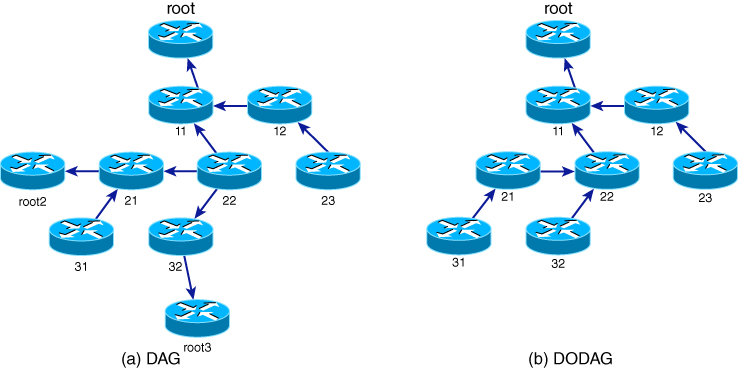
Figure 8.4 Example of a DAG and a DODAG.
To establish and maintain routes, RPL uses three different types of ICMPv6 control packets:
- DAG information object (DIO)
- DAG information solicitation (DIS)
- destination advertisement object (DAO)
The upward route construction, the one used between smart meters and the core network, is managed by transmitting DIO messages in multicast. DIO messages contain information that allows discovering a RPL instance, calculating its own rank and choosing parents in the DODAG. The rank contained in the DIO message is the rank of the node sending the DIO message and determines the relative position of a node in the DODAG. The rank is computed by the objective function using routing metrics, and its purpose is to avoid loops. The downward route construction, which is optional in RPL, is managed by the DAO messages to propagate information about the destination in the upward direction. To construct the downward routes, there are storing and non‐storing modes. Finally, DIS control packets are utilized to solicit a DIO message from a RPL node.
8.3.1.3 Routing Table Maintenance under RPL
As previously stated, DIO messages are periodically transmitted to build and maintain the RPL DODAG. However, if the network is stable, the DIO message frequency is decreased to reduce the overhead of signaling messages. On the contrary, if the condition of the network is not stable, more DIO messages have to be transmitted. This timing function is called trickle timer [28]. If a received DIO message does not imply any change on the receiver in terms of rank, parent set, or preferred parent, the DIO is considered consistent. As long as consistent messages are received, the interval between DIO messages is exponentially doubled to reduce the overhead of periodic messages. Conversely, when the network is not stable and DIO messages are inconsistent with the known topology, more DIS and DIO messages are needed to update the node routing tables. Messages such as multicast DIS without a solicited information option or DIO messages containing infinite rank are considered inconsistent and cause the trickle timer to reset, and the interval time is set to its minimum value. The trickle algorithm allows to be reactive in case of a change or failure in the network while minimizing the overhead when the network is stable.
For the downward route construction, a DelayDAO is sent to govern the emission of the DAO messages. At each transmission of a DAO message, a random interval is chosen before the actual transmission.
8.3.1.4 Routing Strategy: Metrics and Constraints
A metric in RPL is a quantitative value, and it is used to evaluate the path cost. Vasseur et al. (2012) [29] define two kinds of metrics that can be used for path calculation:
- the link metric, which concerns the link's attributes, e.g., link quality level (LQL), ETX, latency, and throughput; and
- the node metric, which takes into account the node state and attribute (NSA) such as energy (remaining energy, power source) or min‐hop (number of hops to the root).
RPL supports also a constraint‐based routing where the constraint may be applied on both link and nodes. If a link or a node does not satisfy a constraint, it is discarded from the parent set.
This constraint is used to include or eliminate a link or a node that does not meet a specific criterion. For instance, the objective function will not choose a path that traverses a node that is battery powered or a link with low ETX. The RPL objective function could combine metrics and constraints to compute the best path.
8.3.1.5 Path Computation under RPL
To compute the optimal path, the objective function plays a major role in the RPL protocol. To this aim, the two following algorithms have to be defined:
- the computation of the node's rank according to one or several metrics; and
- the parent selection operation according to metrics and constraints.
Two objective functions have been defined by the ROLL working group: objective function zero (OF0) and minimum rank with hysteresis objective function (MRHOF) and are presented next.
The Objective Function Zero
The OF0 [30] works by computing the rank based on the addition of a scalar, representing the link properties to the rank of the preferred parent. The scalar value is normalized between 1 and 9 for expressing the link properties, with 1 for excellent, and 9 for very poor. Note that any kind of metric could be used for the scalar value. This objective function allows to find the closest grounded root (a root that offers connectivity to the application goal) by selecting a preferred parent and a backup successor if available.
The rank computation is given by the algorithm below:
where:
- R(P) is the preferred parent's rank
- Sp (the step_of_rank), Sr (stretch_of_rank), and Rf (rank_factor) are respectively the expression of the link properties normalized between 1 and 9, the maximum augmentation to the step_of_rank of a preferred parent to allow the selection of an additional feasible successor and a value used to increase the importance of the link properties.
- MinHopRankIncrease is a multiplying factor that plays a major role in the rank computation by reflecting the impact of the metric on the rank increase. The default value is 256, as it is described in[26].
OF0 parent selection is governed by several rules (see Section of [30]), but the most important is that the selected parent must be the one that causes the lesser resulting rank for the node. This selected parent becomes the “preferred” parent.
The Minimum Rank Hysteresis Objective Function
MRHOF [31] optimizes the path to the root that minimizes a defined metric. However, it avoids changing this path frequently. Light metrics variations cause changes in the network that are decreased by introducing a hysteresis. MRHOF works with additive metrics and introduces the path cost for the rank computation, which specifies the property of the path to the root regarding the employed metric. The path cost is calculated by the sum of the path cost advertised by the parent and the link metric cost to the parent.
The rank computation for MRHOF is given by the algorithm below:
where:
-
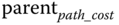 is advertised by the parent and represents the pathcost of the parent; and
 - link_cost is the cost associated with the parent's link regarding the selected metric.
MRHOF parent selection is governed by a hysteresis function given by the equation below where ![]() and
and ![]() are respectively the path cost to parent 1 and parent 2. PP is the selected parent designated as Preferred Parent, P1 is the current best parent, and P2 is a candidate parent.
are respectively the path cost to parent 1 and parent 2. PP is the selected parent designated as Preferred Parent, P1 is the current best parent, and P2 is a candidate parent.
where Threshold is the hysteresis function, i.e., the minimum difference between the cost of the path through the preferred parent and the cost path of a candidate parent to trigger the selection of a new preferred parent. This objective function allows for selection of the route toward the root with the lowest path cost, e.g., minimum hop counts if the hop‐count metric is used.
8.3.1.6 Summary of the RPL DODAG construction
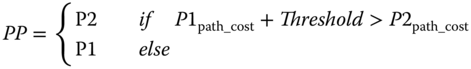
Figure 8.5 shows an example of the upward route construction using the hop‐count metric. Once the trickle timer is expired, RPL root will broadcast a DIO message containing its rank. Nodes in the coverage area of the root (i.e., yellow circles) will receive the DIO message and process it. If the DIO message had been corrupted, it would have been discarded. Since the root is the sink of the network, nodes 1 and 2 can not be closer to the root, so they will add the root as their preferred parent and compute their rank. To test if a candidate neighbor is eligible to be a preferred parent, a node will verify if the rank contained in the received DIO message added to a RPL parametric value (min_hop_rank_increase) is less than its rank. Then node 1 and 2 will broadcast their own DIO message with their new computed rank. Note that since the root has a smaller rank than the one advertised in nodes 1 and 2 DIO messages, nodes 1 and 2 will not be considered as potential parents for the root. It is worth mentioning that ranks shown under node names in this example depend on the objective function, and values shown beside edges represent the link quality (i.e., ETX). The arrows between nodes represent the upward route, and when a node installed at least one of them, it is considered to have joined the DODAG. It has to be noted that a node may either stay silent and wait for a DIO message or it may send a DIS message during the initialization process.
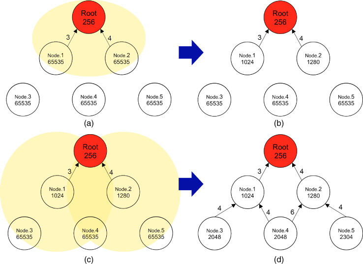
Figure 8.5 Example of an upward route construction with RPL.
8.3.1.7 Reactive Routing Protocol
In a reactive‐based routing protocol, routes are built and maintained only when they are requested, which means that there is no need to maintain a route if there is no traffic. Thus, a delay is added before transmitting a data packet due to the route construction. Contrary to proactive protocols, reactive protocols do not need to send routing information periodically and, thus, will require less energy or CPU resources. However, the quantity of routing messages will greatly depend on the frequency of the traffic in the network.
8.3.1.8 Topology Management under AODV
AODV [32] is a well‐known reactive routing protocol designed for use in mobile ad hoc networks (MANET). It floods the network with broadcast route‐request messages when a needed route that does not exist.
To establish and maintain routes, AODV uses five types of messages:
- RREQ: route request
- RREP: route reply
- RERR: route error
- RREP‐ACK: route reply acknowledgment
- HELLO: link status monitoring
When a source node expects to establish a route to a destination, it broadcasts a RREQ packet. Once the destination is reached (or an intermediate node that knows the route to the destination is reached), a RREP message is sent back to the RREQ sender, which ends the route discovery process. If a RREP message is received, the route discovery operation is over. Otherwise, after certain period, it repeats the RREQ message and increases the waiting period. If there is no RREP message, this process can be repeated several times (by default, RREQ_RETRIES = 2). If there is still no response after three attempts, the route search process is aborted. Consequently, a new route request will be initiated after ten seconds. A node receiving a RREQ packet will send a RREP (route reply) packet if it is the destination or if it has a route to the destination with a sequence number greater or equal to the RREQ packet; otherwise, it rebroadcasts the RREQ packet. Each node keeps a trace of the source IPs and the identifiers of the RREQ packets. In case of receiving a RREQ packet that they have already processed, they delete it.
Once the source has received the RREP packets, it can start sending data packets to the destination. If the source subsequently receives a RREP containing a higher or equal sequence number but with a smaller number of hops, it will update its routing information to that destination and start using the best route. A route is maintained as long as it continues to be active, in other words, as long as data traverse between the source and the destination. The link expires when there is no more data in transit on the link and after a predefined delay. If the link is cut, the end node sends a RERR (route error) packet to the source node to warn that the destination is currently unreachable. If the source node still wants to get a route to that destination, it must start the route discovery process again.
Concerning the routing table, each entry contains nine fields. In addition to IP address of the destination node, the fields contain routing information and information related to the qualitative state of the route for maintenance purposes. Unlike other protocols, AODV only maintains information about the next hop in the route, not the entire routing list. This saves memory and decreases overhead for route maintenance. The routing table also contains information enabling the host to share information with other nodes when link states change. To ensure the information is the latest one available in the route table entry, a sequence number for the IP address is included in the message. This sequence number is called the “destination sequence number.” It is updated each time a node receives a RRER, RREP, or RREQ message.
To offer connectivity information, nodes that are part of an active route can broadcast local Hello messages. Every HELLO_INTERVAL, the node will check if it has sent a broadcast message during the last interval, and if it has not, it will broadcast a RREP message with a TTL set to 1. Within a dedicated period, if a node that has received a Hello message from a neighbor does not receive any packet from that neighbor, the node will assume the link is lost and will send a RRER route error message. Figure 8.6 shows a route search on the initiative of the node A in the direction of J. The RREQ message is broadcast from node A to all its neighbors. When node G receives the message, it returns a RREP message to node A through node E.
- The RREQ route request message is sent to search for available routes; it is made of frame size
 in length.
 - The RREP route response to demand message is sent to indicate available routes to the originator of the demand; the frame consists of
 .
. - The RRER is sent to report routes with potential errors to the originator of the demand; it consists of
 .
.
Figure 8.6 Example of an AODV route detection between node A and G.
A route reply acknowledgment (RREP‐ACK) message is sent in response to a RREP message with the ‘A’ bit set to 1 when there is danger of unidirectional links preventing the completion of a route discovery cycle. It indicates that another available route is already used.
8.3.2 Reactive Routing Protocol in a Constrained Network
Several proposals emerged to simplify and adapt AODV for LLNs. In 2011 and 2012, with the use of an adaptation of AODV in G3‐PLC standard in smart grids networks, a single LOADng specification emerged, as the next version of AODV.
6LoWPAN Ad Hoc On‐Demand Distance Vector Routing (LOAD) and Lightweight On‐demand Ad Hoc Distance‐vector Routing Protocol Next Generation (LOADng) are both routing protocols based on the AODV reactive routing protocol. LOADng is the latest version of LOAD, where many features have been reviewed to make LOADng more efficient and extensible. In LOADng several extensions have been included to improve the performance under specific scenarios such as LLN, by reducing the network overhead. Thus, LOADng, LOAD, and AODV share many common points:
- A node that has data to transmit to a destination but has not any information related to this destination in its routing table: it sends a RREQ message. If the message is received by a node that has been already transmitted by itself, it will discard the message to avoid breaking existing routes. Intermediate nodes construct the reverse route upon the reception of the RREQ message.
- When the destination node receives the RREQ message, it can generate a RREP message immediately and, thus, minimize the time to establish the path. It could also wait to receive several RREQ messages with better metric to optimize the path at the cost of a longer path establishment delay.
- To detect broken or asymmetric links, intermediate nodes can request an acknowledgment during the forward route to the destination construction.
- Except for LOADng, when a node is no longer able to forward packets to the next hop, a local repair mechanism is triggered to solve the problem. In case the local repair mechanism fails, a RRER message is sent to the originator of the message.
In Figure 8.7 an example of route construction using LOADng routing protocol is illustrated.

Figure 8.7 Example of a route construction with LOADng.
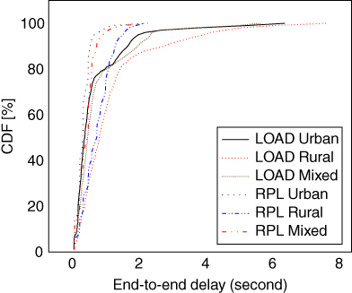
Figure 8.8 End‐to‐end delay comparison.
8.3.2.1 Performance Evaluation
As LOAD and RPL are both specifically designed for LLN, hereafter, we will present a performance evaluation comparison of these two protocols, Table 8.2 summarize their specificities.
Comparing RPL and LOAD will mainly depend on the topology (e.g., density). In a stable network, the round‐trip time for a data request (i.e., end‐to‐end delay) will tend to be better with RPL, due to the time needed to build the path using the LOAD RREQ message. Thus, thanks to the trickle timer, RPL will decrease significantly the control traffic as long as the network stays stable. When the condition of the network evolves unexpectedly (i.e., a node loses its parent, a path cost changes), RPL will reset the trickle timer and send more DIO messages to recompute the DODAG. This explains the additional control traffic in RPL, and may result in a broadcast storm, caused by the issue of DIO messages with increased DODAG version number (global repair). A global repair of the DODAG is triggered by the root. It re‐computes the DODAG and increases the end‐to‐end delay where LOAD will be less affected by the network variation. In smart grid applications, end‐to‐end delay tolerance could vary from below 10![]() to more than two seconds (e.g., smart meter reading). On the other hand, a teleprotection, for instance, which ensures the protection of network equipment from severe damage by managing the grid load, requires fast signals to pilot protective relays: no more than 10
to more than two seconds (e.g., smart meter reading). On the other hand, a teleprotection, for instance, which ensures the protection of network equipment from severe damage by managing the grid load, requires fast signals to pilot protective relays: no more than 10![]() [33]. Figure 8.8 shows the end-to-end delay comparison between LOAD and RPL under different smart grid scenarios.
[33]. Figure 8.8 shows the end-to-end delay comparison between LOAD and RPL under different smart grid scenarios.
Since in LLNs, nodes have constrained memory, smart meters will only store a dozen entries, whereas the routing table usually contains hundred of thousands of routes in IP core routers. As a consequence of flooding, each smart meter in a LOAD network receiving a RREQ message will install a route toward the sender, resulting in a large number of unnecessary routing entries. The same issue occurs when a node is situated on a route of a RREP message. On the contrary, most routers in RPL network have the default entry toward the preferred parent. However, when RPL operates in storing‐mode, nodes that are chosen as preferred parent have to store the downward route and may cause critical issues such as loops, in case a node runs out of energy.
Concerning the path efficiency, since RPL computes a DODAG from a sub‐topology of the physical network, the traffic has to follow paths along the DODAG even if a more optimal path exists in the physical world. Those protocols produce a sub‐optimal solution, which can be improved by carefully selecting parameters for the metrics used to arbitrate the chosen links. For instance, LOAD uses the LQI (link quality indicator) of the 6LoWPAN physical layer in addition to the Hop distance.
Figure 8.9 shows the root data delivery ratio of a 100‐node topology for RPL and LOAD, respectively, after two hours of simulation. As the traffic is set to start when the simulation initiates, RPL demonstrates additional delay before the actual data packet reception. However, RPL attains high performance once the DODAG is established. Concerning LOAD, results indicate that data is received quickly once the network is initiated; however, it takes time for LOAD to reach the same DDR as RPL.
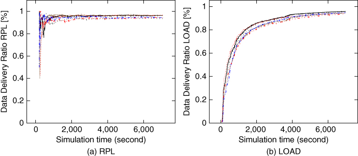
Figure 8.9 Data delivery ratio comparison.
In RPL, packets are sent only after the DODAG is constructed. Thus, if the metric chosen for constructing the DODAG is hop count, then RPL will compute a DODAG with minimum hops. Due to the flooding mechanism of LOAD, nodes construct the path using the first RREP message arrived, which is not necessarily the optimal one in terms of hops. The packet will follow a non‐optimal route until subsequent RREP message reception to update the path.
In terms of overhead, differences between the protocols will mainly depend on the implementation and employed parameters. The stability of the network has a significant impact on RPL protocol, since its parameters should be carefully selected to handle specific network circumstances. In LOAD, route hold time (RHT) will greatly impact the frequency of the flooding and, consequently, will increase the overhead. The number of nodes in the network is also critical in LOAD since high density in the network will increase the overall overhead. In RPL, we expect the maximum overhead at the beginning of the DODAG construction and then a reduction as the network becomes stable, due to the behavior of the trickle algorithm.
8.3.2.2 Summary on Routing Protocols
Choosing between reactive and proactive routing protocols in a smart grid network depends on multiple factors. The application, which identifies the type of traffic, has a major role in choosing the routing protocol and its corresponding parameters. Several parameters will also depend on the density of smart meters and the type of topology, i.e., number of maximum hops to the root. Furthermore, the priority of the traffic has an impact on the routing strategy as well, i.e., if the application is tolerant to high end‐to‐end delay. However, each protocol has different implementation issues attaining, thus, different performances. As a result, several parameters need to be properly configured in order to satisfy the requirements of the considered network and application.
RPL, for instance, is known to work well in multi‐point‐to‐point applications, a typical scenario in smart grid network, where data concentrators will receive the data from a large amount of smart meters in the NANs. LOADng address 6LoWPAN ad hoc on‐demand distance vector routing (LOAD) multi‐point‐to‐point issue and offer a similar performance to RPL at the cost of delay for the route discovery process. In a smart grid scenario, for typical monthly readings, the delay could not be a critical issue, so both protocols could be chosen depending on the acceptable overhead. The frequency of the traffic is also a major issue in smart grid networks, where a stable routing graph, such as RPL constantly maintained DODAG will greatly impact the delay at the cost of energy consumption. On the other hand, if the smart grid traffic is sparse, the need of maintaining a routing graph at the cost of high control traffic is not essential. For example, millions of smart meters using RPL have been installed in California mandated by the California Public Utilities Commission (CPUC) while French Enedis has chosen LOADng for the widely deployed Linky smart meters in France.
Furthermore, today smart grid devices have multiple heterogeneous communication interfaces, which leads to hybrid networks. Such a feature allows to enhance reliability and robustness by taking advantages of all available technologies (i.e., PLC and 802.15.4) [34].
8.4 Conclusion
This chapter was devoted to present and discuss both infrastructures and communication architectures as well as technologies and protocols employed in smart grid systems. We especially detailed the necessary requirements next‐generation smart grid systems should address in order to enable dynamic and evolving architectures. In addition, we compared certain existing routing families that efficiently fulfill the requirements of a constrained‐based smart grid environment.
Current smart grid systems, which rely on advanced metering infrastructure (AMI), are facing several issues as prosumers demands are constantly growing while simultaneously production capacity is less predictable due to the increasing popularity of local renewable production units (i.e., a decentralized energy production system). In order to have a better management of the network, utilities require tools to forecast both consumption and local production of end points, as well as mechanisms to remotely control them. As a consequence, current smart grid systems need to open up to Internet‐based architectures. They will therefore move from a centralized to a distributed configuration in which end users could be more involved and that might have different management levels.
Such configuration requires dedicated energy management system (EMS), which will collaborate with both end users and smart meters deployed by a DSO, in order to locally handle the management of a given set of nodes. Using such EMSs will help any provider deploy new energy services while ensuring users' data privacy. However, security concerns arise from this configuration and must be considered along with its deployment.
Regardless of the configuration chosen, smart grid networks mostly remain on constrained devices used in large topologies As a result, we also insist in this chapter in presenting two families of routing protocols that efficiently manage the routing issues in such topologies. Proactive routing protocols, such as RPL, construct routes a priori, i.e., before they are required, and all nodes are perfectly aware of the path to any destination. Applications that need low end‐to‐end delay will benefit from such a proactive protocol, as once the routing graph is built, traffic could be sent without any additional time. On the other hand, reactive routing protocols, such as LOAD, construct the routes only when required. Therefore, these protocols allow applications to overcome any failure in the network without waiting for a complete reconstruction of the routing graph. However, they add delay in the data traffic.
References
- 1 Eurelectric (2015), Power Statistics and Trends: The Five Dimensions of the Energy Union.
- 2 Lefrancois, M., Habault, G., Ramondou, C., and Francon, E. (2016) Outsourcing Electric Vehicle Smart Charging on the Web of Data, in GREEN 2016 IARA International Conference.
- 3 Ouya, A., Martinez De Aragon, B., Bouette, C., Habault, G., Montavont, N., and Papadopoulos, G.Z. (2017) An Efficient Electric Vehicle Charging Architecture based on LoRa Communication, in Proc. of the IEEE International Conference on Smart Grid Communications (SmartGridComm).
- 4 Habault, G., Lefrancois, M., Lemercier, F., Montavont, N., Chatzimisios, P., and Papadopoulos, G.Z. (2017) Monitoring Traffic Optimization in Smart Grid Architectures. IEEE Trans. Industrial Informatics.
- 5 Tsoleridis, C., Chatzimisios, P., and Fouliras, P. (2016) Vehicle‐to‐Grid Networks: Issues and Challenges, CRC Press, pp. 347–369.
- 6 Bush, S.F. (2014) Smart Grid: Communication‐Enabled Intelligence for the Electric Power Grid, Wiley‐IEEE Press.
- 7 Ashton, K. (2009), “That ‘Internet of Things’ Thing”, http://www.rfidjournal.com/articles/view?4986.
- 8 IEEE Computer Society (2016), IEEE Draft Standard for Information Technology‐Telecommunications and Information Exchange Between Systems‐Local and Metropolitan Area Networks‐Specific Requirements‐Part 11: Wireless LAN Medium Access Control (MAC) and Physical Layer (PHY) Specifications: Amendment 2: Sub 1 GHz License Exempt Operation.
- 9 LoRa Alliance (2015), LoRaWAN Specification v1.0, https://www.lora‐alliance.org/portals/0/specs/LoRaWAN%20Specification%201R0.pdf.
- 10 3GPP (2016), LTE Category M (Cat M). Release 13.
- 11 IEEE Computer Society (2016), IEEE Standard for Low‐Rate Wireless Personal Area Networks (LR‐WPANs), IEEE Std 802.15.4‐2015 (Revision of IEEE Std 802.15.4‐2011).
- 12 IEEE Computer Society (2012) IEEE Standard for Local and metropolitan area networks–Part 15.4: Low‐Rate Wireless Personal Area Networks (LR‐WPANs) Amendment 3: Physical Layer (PHY) Specifications for Low‐Data‐Rate, Wireless, Smart Metering Utility Networks.
- 13 Galli, S., Scaglione, A., and Wang, Z. (2011) For the Grid and Through the Grid: The Role of Power Line Communications in the Smart Grid. Proceedings of the IEEE, 99 (6), 998–1027.
- 14 Lawton, G. (2004) “Machine‐to‐machine Technology Gears up for Growth”. Computer, 37 (9), 12–15.
- 15 Fan, Z., Kulkarni, P., Gormus, S., Efthymiou, C., Kalogridis, G., Sooriyabandara, M., Zhu, Z., Lambotharan, S., and Chin, W. (2013) Smart grid communications: Overview of research challenges, solutions, and standardization activities. IEEE Communications Surveys & Tutorials, 15 (1), 21–38.
- 16 Chatzimisios, P., Stratogiannis, D., Tsiropoulos, G., and Stavrou, G. (2013) A survey on smart grid communications: from an architecture overview to standardization activities. Handbook of Green Information and Communication Systems.
- 17 Camhi, J. (2015), BI Intelligence projects 34 billion devices will be connected by 2020, http://www.businessinsider.com/bi‐intelligence‐34‐billion‐connected‐devices‐2020‐2015‐11?IR=T.
- 18 Russell, B. and van Duren, D. (2016) Practical Internet of Things Security, Packt Publishing.
- 19 oneM2M (2015), Functional Architecture, http://www.onem2m.org/images/files/deliverables/TS‐0001‐ Functional_Architecture‐V1_6_1.pdf.
- 20 IoT‐A (2013), Final Architecture Reference Model, http://www.iot‐a.eu/public.
- 21 Industrial Internet Consortium (2015), The Industrial Internet Reference Architecture, https://www.iiconsortium.org/IIRA‐1‐7‐ajs.pdf.
- 22 Habault, G., Bonnin, J.M., and Hursti, J. (2016) Defining a Distributed Architecture for Smart Energy Aware Systems, in CSD&M 2016 : 7th International Conference on Complex Systems Design & Management.
- 23 Vasseur, J.P. (2008) Overview of Existing Routing Protocols for Low Power and Lossy Networks, Internet‐Draft draft‐levis‐roll‐overview‐protocols‐00, Internet Engineering Task Force. URL https://datatracker.ietf.org/doc/html/draft‐levis‐roll‐overview‐protocols‐00, work in Progress.
- 24 Vasseur, J.P. and Cullerot, D.L. (2007) Routing Requirements for Low Power And Lossy Networks, Internet‐Draft draft‐culler‐rl2n‐routing‐reqs‐01, Internet Engineering Task Force. URL https://datatracker.ietf.org/doc/html/draft‐culler‐rl2n‐routing‐reqs‐01, work in Progress.
- 25 Yi, J., Clausen, T., and Igarashi, Y. (2013) Evaluation of routing protocol for low power and lossy networks: Loadng and rpl, in IEEE Conf. Wireless Sensor (ICWISE), IEEE, pp. 19–24.
- 26 Winter, T., Thubert, P., Brandt, A., Hui, J., Kelsey, R., Levis, P., Pister, K., Struik, R., Vasseur, J., and R., A. (2012), RPL: IPv6 Routing Protocol for Low‐Power and Lossy Networks, RFC 6550.
- 27 Ancillotti, E., Bruno, R., and Conti, M. (2014) Reliable data delivery with the IETF routing protocol for low‐power and lossy networks. IEEE Trans. Industrial Informatics, 10 (3), 1864–1877.
- 28 Levis, P., Clausen, T., Hui, J., Gnawali, O., and Ko, J. (2011), The Trickle Algorithm, RFC 6206.
- 29 Vasseur, J., Kim, M., Pister, K., Dejean, N., and Barthel, D. (2012), Routing metrics used for path calculation in low‐power and lossy networks, RFC 6551.
- 30 Thubert, P. (2012), Objective Function Zero for the Routing Protocol for Low‐Power and Lossy Networks (RPL), RFC 6552 (Proposed Standard).
- 31 Gnawali, O. and Levis, P. (2012), The Minimum Rank with Hysteresis Objective Function, RFC 6719 (Proposed Standard). URL http://www.ietf.org/rfc/rfc6719.txt.
- 32 Perkins, C., Belding‐Royer, E., and Das, S. (2003), Ad hoc On‐Demand Distance Vector (AODV) Routing, RFC 3561 (Experimental). URL http://www.ietf.org/rfc/rfc3561.txt.
- 33 (2009) Wireless Systems for Industrial Automation: Process Control and Related Applications (ISA100.11a), International Society of Automation (ISA), Sep. 2009. ANSI/ISA‐100.11a‐2011, pp. 1–792.
- 34 Lemercier, F., Montavont, N., Toutain, L., Vijayasankar, K., Vedantham, R., and Itron, P.C. (2016) Support for hybrid network in RPL, in SmartGridComm, IEEE, pp. 527–532.