
16
Channel Access Modelling for EV Charging/Discharging Service through Vehicular ad hoc Networks (VANETs) Communications
Dhaou Said and Hussein T. Mouftah
School of Electrical Engineering and Computer Science (EECS), University of Ottawa, Ottawa, Canada
Nomenclature
- ACs
- access categories
- ACK
- acknowledgment
- Cd
- communication density
- C_O
- cut‐off parameter
- Cr
- communication range
- CW
- contention window
- CCH
- control channel
- Dch
- charging/discharging rate
- EDCA
- enhanced distributed channel access
- EV
- electric vehicle
- EVSE
- electric vehicle supply equipment
- EV‐SG
- EV‐to‐smart‐grid interaction
- G2V
- grid‐to‐vehicle
- ITS
- intelligent transportation system
- LTE
- Long‐Term Evolution
- Mf
- message frequency
- PLC
- power line communication
- OBU
- on board unit
- RSU
- road side unit
- SAE
- Society of Automotive Engineers
- SCH
- service channel
- SG
- smart grid
- SoC
- state of charge
- TOUP
- time of use pricing
- Vd
- vehicle density
- V2G
- vehicle‐to‐Grid
- VANETs
- vehicular ad hoc networks
- WAVE
- wireless access in vehicular environment
- WSA
- wave service advertisement
16.1 Introduction
As we see our society becomes more and more connected with an open and global living environment, the transportation technologies have to play an important and central role in cites. Moreover innovative transportation solutions are emerging as a next‐generation approach for the vision of the smart city challenge. Added to the transport electrification concept, especially the electric vehicle (EV), which is beneficial in term of oil dependency and greenhouse gases (GHG) emissions reduction, the recent intelligent transportation systems (ITS) and networks development are expected to improve the electric energy management capabilities in cities while conserving clean, sustainable, economic, and safe surroundings.
In terms of electric power, the load introduced by EVs charging operations will be one of the most important challenging issues for demand response systems in the smart grid. Indeed, the efficient energy management for EVs and electric vehicle supply equipment (EVSE) will become central to achieving efficient operations of the smart grid. Moreover, the smart grid is required to enable penetration of intermittent generation sources, enable adaptive electricity price [1–3], be self‐healing, optimize assets [4, 5], enable high penetration of EVs, and enable the EV grid stability participation. In addition to counting and pricing in the smart grid, the real‐time control over smart grid infrastructure and energy usage promises one of the largest potentials in load management and energy saving [6–8].
For an EV, finding a vacant EVSE to plug in, especially in peak hours, is always time consuming and frustrating to drivers when the charging service is seen by the smart grid as a trade‐off between consumer satisfaction and grid stability. For this end, it is necessary to design EV–smart grid communication architectures taking into account the time constraint and reliability which is expressed as a level of customer's satisfaction without stressing the grid. This communication architecture could be based on real‐time information, such as EV and EVSE status, which have to be exchanged with the smart grid. As a result, the EV can be informed of the nearest available EVSE in advance since it is on the road. This can reduce the peak demand and improve EVs satisfaction with grid stability, but it requires a large area connectivity, which has to be maintained between the smart grid and EVs.
In this chapter, we discuss the technical environment of the charging/discharging problem. We introduce a survey of communication technologies used for the smart grid. By the end we present a specific case study of the channel access modelling for the EV charging service based on the IEEE802.11p/DSRC protocol.
16.2 Technical Environment of the EV Charging/Discharging Process
The EV charging/discharging process is described by the time and the place where it occurs. To reduce its potential risk to the electric power system, which exists even with a low PEV penetration [9, 10], smart charging technics based on EV scheduling algorithms can be used. Indeed, the EV charging cycle can be altered by external events, allowing for adaptive charging habits, providing the EV with the ability to integrate easily into the whole power system. To achieve those goals, a guidance model [[11]] has to be considered with safe, secure, reliable, and sustainable information exchangeable between different grid parts.
In this section we present an overview of electric vehicle supply equipment (EVSE) used at home and away from home (parking work place) and the fast‐charging station. Second, we discuss the inductive charging technique as an innovative EV‐charging scheme, and we clarify the potential that this method holds for EVs.
16.2.1 EVSE Overview
As the EV industry emerges at the beginning of the 21st century, the development of the infrastructures for recharging at home, at work, and at public locations is imperative. EVSE consists of all the equipment needed to deliver electrical energy from an electricity source to a PEV battery. The EVSE communicates with the PEV to ensure that the plug is securely connected to the vehicle receptacle before supplying a safe flow of electricity. There are three primary types of EVSE, which are classified based on charging places (at home, work places, commercial places, and supply stations), charging speed, and charging electric power (voltage, current).
- At home: the level 1 method uses a standard 120 volts AC (VAC) used for both residential and commercial buildings. Typical voltage and amp ratings can be from 110 to 120 volts AC and 15 or 20 amps, respectively.
- At parking or work place: the level 2 is described as the standard method for the EVSE for both private and publicly available facilities. It specifies a single‐phase branch circuit with voltage ratings from 220 to 240 volts AC and a current as high as 80 amps AC (100 amp‐rated circuit). However, current levels that high are rare, and a more typical rating would be 40 amps AC, which allows a maximum current of 32 amps. This provides approximately 7.7 kW with a 240 VAC circuit [[12]].
- DC fast charging station: this type of charging connection can raise the rate of charge to approximately 75–80% in as little as 20–30 minutes, depending on battery size. This type of EVSE uses an off‐board charger that transforms AC power to DC and bypasses the on‐board charger. Generally, 208 V three‐phase or 480 V service is required for this type of charging and may not be commonly available. In many cases, a new separate service will need to be installed by the local utility.
The communication standards when an EV is being charged or plugged in at EVSE are defined by the Society of Automotive Engineers (SAE) as SAE J2293, SAE J2836/1 and J2847/1, SAE J2836/2 and J2847/2, SAE J2836/3 and J2847/3, SAE J2931/1 and SAE J2931 [[12]].
16.2.2 Inductive Chargers: Opportunities and Potential
As mentioned before, the most common method for EV charging is the usage of a cable plug‐in system used either at home, at work, or at specific charging stations spread across some cities. An alternative to this charging method is wireless inductive charging.
The inductive charging technique focuses on the ability to charge while driving and the reduction in the space that must be dedicated to the charging infrastructure in urban areas. Moreover, with this charging method it is possible to just position the EV on a charging point and start the contactless charging process without any additional effort.
The inductive charging technique can take place statically at short stops or during short or long parking phases (the traffic light, the bus stop, or the taxi stand, while it would be impossible with the conductive charging option). It can be also possible dynamically, where the EV can charge while driving, which probably can decrease the size and cost of the battery.
This technique offers several advantages over the conductive charging method (using a cable):
- The inductive charging process is automated and easy to use.
- The system is safe against vandalism and environmental influences (e.g., humidity) because all devices are encapsulated in the vehicle or they are underground.
- There is no negative impact on the cityscape (all devices and grid connections are underground).
- The frequencies used for static inductive charging are between 80 and 500 kHz [[13]].
- The EV for vehicle‐to‐grid applications (V2G) availability is higher (e.g., for using the vehicle's battery to store excess energy in the grid).
16.3 Overview of Communication Technologies in the Smart Grid
Many technologies implemented for sensors and wired and wireless networks are already used in the smart grid. The EVs, as a new actor in the SG, need at any time the EV charging service at home or public fast charging service to fill up its battery or supplying power (V2G). As a result, a huge EV penetration, which can be translated to variable spatiotemporal power demand, can cause instability to the grid and an overloading of transformers added to the frequency regulation problem especially during rush hours [[14]]. However, to reduce the negative impact of the EV penetration and due to the EV dynamic mobility nature, new challenges on monitoring and communication are brought up.
In the following, we present the power line communication (PLC) technology and wireless communication, which can be used in electric mobility.
16.3.1 Power Line Communication
The key advantage of PLC is that the already existing grid infrastructure reaches every grid component and there is no need for new wires as a communication support. It uses the existing electrical lines as communication medium, and data is sent on the power lines by superposing a modulated high‐frequency carrier signal on the line voltage. As a result, the PLC deployment cost is relatively low compared to other wireline or wireless technologies. Despite all those advantages, for environment regulations, the PLC cannot be allowed in some countries such as Japan. Moreover, in some cases, the PLC range can be limited by high attenuation caused by transformers.
There are three different types of PLC technologies which are classified by the frequency band and data rate used.
The oldest one is the ultra‐narrow band technology. It only provides a data rate around one hundred bits per second [[15]]. It is used for remote communication with electrical meters (meter reading) in North America.
The second one is broadband PLC, which uses the 1.8–250 MHz frequency band and the physical data rate varies between a few megabits to hundreds of megabits. It is used to bring Internet service to homes and small businesses over the electrical distribution system or as in‐house networking [[16]].
The third one is the narrowband PLC, which operates in the 3–500 kHz band and provides lower data rates. Typically, PLC applications can include:
- automatic meter reading and management (AMR/AMM) for the smart grid;
- PLC over medium‐voltage power distribution network for distribution automation application;
- PLC home area networking (PLC‐HAN) for smart appliances and controls; and
- data communications over DC wires.
In the United States and Asia, there are no restrictions to use narrowband PLC frequencies. Table 16.1 summarizes some frequencies reserved by the CENELECT standard in Europe to be used for some grid applications [[17]].
Table 16.1 Frequencies Reserved by the CENELECT Standard for Smart Grid Communication [[17]].
| Band | Frequencies (kHz) | Applications |
| A | 3–95 | Utilities / smart grid; reserved for use by energy providers and customers' premises |
| B | 95–125 | Unrestricted |
| C | 125–140 | In‐home networks, regulated as to channel access techniques |
| D | 140–148.5 | Alarm and security |
16.3.2 Wireless Communications for EV–Smart Grid Applications
As mentioned before, in the real word the EVs power demand is dispersed in space and time. For an effective interaction between the grid and EVs, the grid has to identify and respond to any particular EV power demand nearly in real time. For this issue, advanced wireless network solutions for short or long ranges such as vehicular ad hoc networks (VANET), ZigBee, 3/4G Long Term Evolution (LTE), worldwide interoperability for microwave access (WiMAX), or wireless mesh networks (WMNs) have to be employed.
Beside the small data traffic generated by an EV charging/discharging application, the EVs interaction with the grid requires a communication coverage capability that can support the huge number of EV demands especially for mobile EVs when high data rate, wide coverage, and quality‐of‐service (QoS) support are needed to support a location‐based application. Cellular networks are qualified to deliver connectivity to EVs and smart grid components with mobility support. Moreover the EV network application can require security support with high available and reliable communication. For example for V2G or G2V interaction, an EV scheduling process needs to receive electricity prices to control the EV charging/discharging without unwanted peaks, cable overheating, or overloading of transformers, which can disrupt the grid stability and increase the losses in the power system. The QoS needed by an effective EV–smart grid interaction is expected to gradually increase with the massive EVs penetration. Basically the communication delays and the outage probability can describe the QoS requirement for a smart grid application. However, when the EV demands exceed the network capacity, the performance of the communication system will degrade and can be unavailable in some cases.
As any network solution, the security challenge for interaction between the smart grid and EVs is very important, and all smart grid applications have to take into account the new techniques and algorithms to provide a safe and reliable solution. The security requirements can be described by three terms such as: the confidentiality level dedicated to the private EV information and the integrity aspect to protect the EV charging data and authenticity. Some attack types for the smart grid networks are defined in [[18]]. Indeed, for example the injection of the negative prices can increase the power consumption, which results in intense grid instability (or create virtual peak periods to destroy or paralyze the power system). Moreover, some attacks can focus on smart meter data input and output and may distort the measures in order to create enormous revenue losses.
16.4 Channel Access Model for EV Charging Service
EVs pose a great challenge for the smart grid by their effect on power grid stability, especially for high EV penetration. To maximize the benefits of using EVs, regulated and optimized charging control needs to be provided by the smart grid. This can be based on exchanged, real‐time information, and large area connectivity has to be maintained between the smart grid and EVs. In this section, we propose a new channel access model for EV charging service scheme for a large number of EVs through VANET communications.
16.4.1 Overview of VANET and LTE
The proposed EV charging service is based on VANET and LTE. In the following, we present briefly the DSRC/WAVE and the LTE characteristics. The dedicated short range communication band (DSRC from 5.850 to 5.925 GHz) is a band used for short to medium range communication in vehicular networks (WAVE) [[19]]. This band includes safety and privates services. DSRC provides a high data rate for mobile nodes and a latency time under 100 ms. As presented in Figure 16.1, the DSRC is formed by seven sub bands, one in the middle, which is the control channel (CCH), and six service channels (SCHs). In WAVE, there are two types of nodes: onboard unit (OBU), located in vehicles and roadside units (RSU), which are located on the road side as service providers relaying or distributing the information. Similar to the OSI model, the WAVE model is presented as a layered architecture composed by IEEE 802.11p [[19]], IEEE 1609.4 [[20]], IEEE1609.3 [[21]], IEEE 1609.2 [[22]], IEEE1609.1 [[23]].
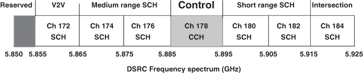
Figure 16.1 Channel allocation in WAVE (DSRC).
Technical references [24–26] present the 3GPP Long Term Evolution (LTE) technology as an attractive solution for mobile broadband services. Indeed LTE uses orthogonal frequency division multiple access (OFDMA) for the downlink and single carrier frequency division multiple access (SC‐FDMA) for uplink, in combination with new antenna technologies such as MIMO. As presented in Table 16.2, LTE promises a downlink data rate of 100 Mbit/s and an uplink data rate of 50 Mbps over a 20 MHz bandwidth. In addition to its simplicity and reduced deployment cost, an LTE cell can support at least 200 users in the 5 MHz band and 400 users in other bands. Moreover, the LTE latency time is very small and does not require more than 10 ms. LTE supports a scalable and flexible bandwidth from 1.4 to 20 MHz. LTE also supports both modes of FDD (frequency division duplex) and TDD (time division duplex). For the mobility characteristics, LTE performance is optimized with a speed lower than 15 km/h. LTE supports speeds of 120 to 350 km/h (or 500 km/h, depending on the frequency band used). All these characteristics make the large‐scale communication technology LTE favorable for V2G interaction design. We present in the next part our proposed EV charging service.
Table 16.2 Mobile Technologies Data Rate Ranges Comparison.
| 3G | WiMax | HSPA+ | LTE | |
| Peak rate (Mbps) | 3 | 128 | 168 | 300 |
| Downlink rate (Mbps) | 0.5–1.5 | 2–6 | 1–10 | 10–100 |
| Uplink rate (Mbps) | 0.2–0.5 | 1–2 | 0.5–4.5 | 5–50 |
16.4.2 Case Study: Access Channel Model
We consider the system presented in Figure 16.2, where some roadsides are given out of the town highlighted by the circle; from each one derives a possible downtown way (input), and a number of EVs and EVPSSs are sharing the road infrastructure area. We suppose that each EV is equipped by an OBU to be linked to the nearest RSU. This RSU is equipped with two communication interfaces VANET and LTE. We assume that these two communication technologies are able to linking EVs, the smart grid (regional manager), and all EVPSSs. We suppose that all EVs can communicate via VANET their positions, EV state of charge (EV SoC), and priority level to the nearest RSU. All RSUs are connected via LTE to the smart grid.

Figure 16.2 System overview.
The proposed EV charging service aims at exploiting the free plug‐in in each EVPSS to monitor the whole EV charging system and provides, according to its initial status, an effective guidance for EVs searching for a supply station. We focused on IEEE802.11p V2I interaction between EVs and RSU, as illustrated in Figure 16.3. In the beginning, the RSU broadcast, over CCH, the EV charge scheduling service description (num SCH, selling price, purchase price). The message format, exchanged between RSU and EV, is described in the following. There are two message types: the first one is the advertisement message sent by RSU, in the CCH channel, describing the electric charging service offered by the smart grid. The description of this message is as follows: num SCH, selling price, and purchase price. The second one is the response of any EV interested in the electric charging/discharging service.

Figure 16.3 Interaction V2I between EVs and RSU.
The EV interested in sale or purchase of electricity will respond by sending its status (position, SoC, priority).
In VANET broadcast transmission context, some references [[27]] use the dynamic contention window (CW) adaptation technique to enhance the performance of V2V and V2I communication. Indeed, this technique is based on the network congestion level. It uses the network local state to estimate the collision rate threshold, which is used for CW adapting. In our work, for the EV charging service, the CW size fluctuates according to the EV priority level, and we prioritize the channel access for EV with high priority. We use the EV priority level parameter to dynamically regulate the CW size.
We suppose the following scenario: all RSUs are equipped with two communication interfaces, VANET and LTE. We suppose that those two communication technologies are able to link EVs, the smart grid, and all EVPSSs (see Figure 16.2 and Figure 16.3). All vehicles are assumed to be equipped with a GPS device, and they are considered to be moving along the highway in one direction (unidirectionally). We consider that the RSU periodically sends the beacon messages to announce EV charging services. According to the EV position, two cases may occur. First, if the EV is within the RSU transmission range, then the EV can connect to the RSU and exchange information related to EV charging service. Second, if the EV is out of the RSU transmission range or there is no RSU, a multi‐hop communication through other EVs will be used to communicate with the nearest RSU to request the charging service announcing.
We focused on this second case. Indeed, in order to establish a connection with the RSU for the EV charging service, the EV keeps actively scanning for beacons on CCH. Once a beacon (i.e., message describing the charging/discharging service) sent by RSU is detected by an EV and if this EV is interested in the charging service, it sends an EV‐charging request frame through a multi‐hop path.
We are interested in the channel access issue. We present in the following a back‐off counter model, based on Markov chains, related to each EV interested on the charging service. We consider that the distributed coordination function adopts an exponential back‐off. This back‐off is a uniform distribution integer between 0 and CW − 1, where CW is the contention window. We assume that an EV has always data to send describing roadside traffic or other, the channel conditions are assumed to be ideal among all neighboring EVs [27, 28].
Figure 16.4 shows the system considered to represent the back‐off counter process for an EV interested in the charging service. The input data is the beaconing frame describing the EV charging service, where the output data is the EV success connection status.

Figure 16.4 Back‐off counter Markov chain model.
The computation of the back‐off counter is achieved as follows:
- select a uniform distribution integer within [0,CW];
- multiply the chosen integer by the time slot at the physical layer;
- if the channel is free, then the back‐off is decremented; and
- when the back‐off reaches zero, the transmission is achieved.
According to Figure 16.4, the transition probability function with time‐homogenous Markov chain is defined as:
where k and l are integer values. The transition matrix is defined as:
The stationary condition related to our Markov chain model is given by:
where ![]() is the vector of stationary distribution. CW − 1 is the state number. Our model is completely characterized by given the transition matrix P and the initial condition
is the vector of stationary distribution. CW − 1 is the state number. Our model is completely characterized by given the transition matrix P and the initial condition ![]() .
.
To solve this Markov chain, we have to solve the balance Equation 16.3 in each state and use the total probability to solve the initial condition ![]() .
.
The total probability condition is:

The ![]() and
and ![]() expressions can be easily derived by simplifying eq. ((16.5)) as:
expressions can be easily derived by simplifying eq. ((16.5)) as:
The probability to have a successful connection in a randomly chosen slot time is:
The probability that there is no transmission in a given slot time (collision or idle condition) is given by:
where n is the number of neighboring EVs.
The probability of collision is given by:
Let Ps be the probability that exactly one EV accesses the channel, conditioned on the fact that at least one EV had access, given there are n EVs,

By increasing Ps or decreasing its denominator, which is given by pcol in Equation 16.8, we can achieve a higher throughput. This can be obtained if the value of (1 − psucc ) increases, which implies that psucc needs to be small. As seen in Equation 16.6, if we increase the value of CW, we can obtain smaller psucc .
The probability of collision, given by Equation 16.8, decreases when CW increases and this effect is more predominant for higher values of n.
We express TH, the normalized system throughput as:

Given:
-
Tst =
 is the average time used during a successful transmission.
 - Tbs is the average time the channel is sensed busy because of a successful transmission.
- Tbc is the average time the channel is sensed busy because of a collision.
- Demp is the duration of an empty slot time.
-

Considering Equation 16.6, we can deduce the optimum CW value, which maximizes the throughput TH as:
In the following, we present the algorithm adaptive CW; it calculates ![]() , which maximizes TH and assigns it to a high‐priority EV.
, which maximizes TH and assigns it to a high‐priority EV.
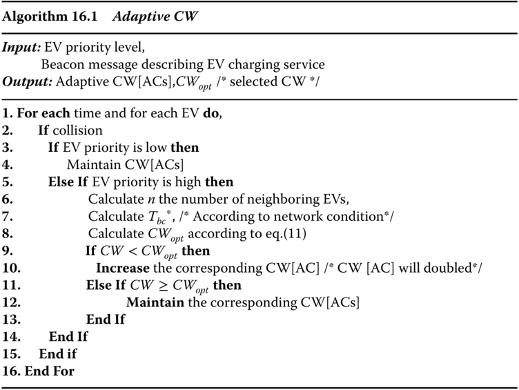
The algorithm, “Adaptive CW” should be run by individual vehicles periodically to update CW [AC] values occur according to the EV priority level and the network condition (e.g., congestion, collision, etc.). In addition to the EV priority level, which is an essential parameter for our adaptive CW algorithm, each EV needs to estimate the network conditions (n and ![]() ) to calculate CWopt
by analyzing the received sequence numbers at MAC layer [[28]].
) to calculate CWopt
by analyzing the received sequence numbers at MAC layer [[28]].
16.4.3 Simulations Results
We evaluate the performance of our proposed channel access model using NS‐2.34 and MATLAB. First, we evaluate some performance metrics such as the probability to have a successful connection in a randomly chosen slot time, the probability of collision, and the probability that exactly one EV accesses the channel, conditioned on the fact that at least one EV had access. Second, we study the efficiency of our access model for the EV charging service compared with the IEEE802.11p standard technique in terms of percentage of successful EV connections in a context of multi‐hop network.
Table 16.3 summarizes the simulations parameters.
Table 16.3 Simulation Parameters.
| Parameter | IEEE 802.11p |
| Carrier frequency [GHz] | 5.9 |
| Bandwidth [MHz] | 10 |
| OFDM guard time [ |
1.6 |
| CWmin | 3,7,15 |
| Cwmax | 1023 |
| Tslot [ |
13 |
| Tsifs [ |
32 |
| Multi‐hop | 3 hops max |
| Transmission range | 2*300 m |
| Vehicle density (Vd) | 10 to 100 EV on 1000 m of road |
| EV speed | 10 m/s, 15 m/s, 20 m/s, |
| Data rate | 6 Mbps |
| Messaging frequency (Mf) | 10 Msg/s, 20 Msg/s, and 30 Msg/s |
| Packet size | 200 bytes |
| Propagation model | Nakagami with m = 2 |
| Power limit | CCH: 44.8dBm/SCH: 33bBm |
| Access scheme | EDCA (supported by NS‐2.34) |
We study the efficiency of our adaptive CW algorithm compared with the standard IEEE802.11p one in terms of the percentage of successful connections for the EV‐charging service.
As shown in Figure 16.5, there is an improvement in the percentage of successful connections ensured by our proposed algorithm; the latter allows more EV‐charging service access per second with fewer losses. This means that, considering the total number of EV charging demands that should be received; the proposed adaptive algorithm is more successful than the standard IEEE802.11p.

Figure 16.5 Percentage of successful EV connection for EV charging service in dense scenarios (100 EVs).
Table 16.4 presents the observation results obtained from Figure 16.5, which illustrates the performance comparison between our adaptive CW algorithm and the standard IEEE802.11p one. Indeed, our adaptive approach increases the percentage of success EV connection for EV charging service with a saving rate of more than 2.1 % and 30.3%, respectively, for the two ranges of time [0,149] and [150,600]. This result proves the effectiveness of our adaptive CW algorithm mainly for a high EV number with different EV charging priority level.
Table 16.4 Percentage of Success EV Connection for EV Charging Service Comparison between Standard IEEE802.11p and Adaptive CW.
| IEEE802.11p standard | Our algorithm: adaptive CW | Saving rates (%) | |
| Time in [0,149] | 93 | 95 | 2.1 |
| Time in[150,600] | 79 | 55 | 30.3 |
16.5 Conclusions
In this chapter, the scheduling problem for electric vehicle (EV) charging/discharging in electric vehicle supply equipment is introduced. We discuss the technical environment of the charging/discharging problem. We introduce a survey of communication technologies used for the smart grid. By the end we present a specific case study of the channel access modelling for the EV charging service based on the IEEE802.11p/DSRC protocol.
References
- 1 Assessment of Plug‐in Electric Vehicle Integration with ISO/RTO Systems, URL: http://www.iso‐rto.org.
- 2 Kaebisch, S., Schmitt, A., Winter, M., and Heuer, J., 2010, ‘Interconnections and communications of electric vehicles and smart grids’, In: Smart Grid Communications (Smart Grid Comm), 2010 First IEEE International Conference on, 2010, 161–166.
- 3 IEC TC/SC 23 62196‐x, Plugs, socket‐outlets, vehicle couplers and vehicle inlets Conductive charging of electric vehicles, Geneva, Switzerland.
- 4 Ruthe, S., Schmutzler, J., Rehtanz, C., Wietfeld, C., 2011, ‘Study on V2G Protocols against the Background of Demand Side Management’, Conference—Interoperability in Business Information Systems IBIS, volume Issue 1, 2011, 33–44.
- 5 Li, N., Chen, L., and Low, S. H., 2011, ‘Optimal demand response based on utility maximization in power networks’, In: IEEE PESGM 2011, 2011.
- 6 Samadi, P., Mohsenian‐Rad, A., Schober, R., Wong, V., and Jatskevich, J., ‘Optimal real‐time pricing algorithm based on utility maximization for smart grid’, In: IEEE SmartGridComm 2010, 2010, 415–420.
- 7 Li. Q., and Negi, R. ‘Distributed Scheduling in Cyber‐physical Systems: The Case of Coordinated Electric Vehicle Charging’, IEEE International Workshop on Smart Grid Communications and Networks 2011.
- 8 Wang, P., Rao, L., Liu, X., Qi, Y., 2011, ‘Dynamic Power Management of Distributed Internet Data Centers in Smart Grid Environment’, IEEE Global Telecommunications Conference GLOBECOM, 2011, 1–5.
- 9 Moses, P. S., Masoum, M. A. S., and Hajforoosh, S., ‘Overloading of distribution transformers in smart grid due to uncoordinated charging of plug‐in electric vehicles’, In: Proc. IEEE PES Innovative Smart Grid Technologies (ISGT), 2012, 1–6.
- 10 Real Wireless, ‘A Comparison of UNB and Spread Spectrum Wireless Technologies as used in LPWA M2M Applications’, (white paper), URL: https://www.thethingsnetwork.org/forum/uploads/default/original/1X/3b1c1ae4a925e9aa897110ccde10ec61f3106b87.pdf, 2015.
- 11 Said, D., Cherkaoui, S., and Khoukhi, L., 2015, ‘Guidance model for EV charging service’, IEEE International Conference on Communications (ICC), London, June 2015, 8–12, 5765–5770.
- 12 ‘Energy Transfer System for Electric Vehicles—Part 1: Functional Requirements and System Architectures’ (Stabilized Feb. 2014), URL: http://standards.sae.org/j2293/1_201402/.
- 13 Kesler, M., 2013, ‘Highly Resonant Wireless Power Transfer: Safe, Efficient, and over Distance’, WiTricity Corporation.
- 14 De Carne, G., Buticchi, G., Liserre, M., and Vournas, C., ‘Frequencybased overload control of smart transformers’, In: IEEE 2015 PowerTech, 1–5.
- 15 Mlynek, P., Misurec, J., Kolka, Z., Slacik, J., Fujdiak, R., 2015, ‘Narrowband Power Line Communication for Smart Metering and Street Lighting Control’, 13th IFAC and IEEE Conference on Programmable Devices and Embedded Systems—PDES 2015.
- 16 Oksman, V., Galli, S., ‘G.hn: The New ITU‐T Home Networking Standard’, IEEE Communications Magazine, October 2009, 138–145.
- 17 ‘The European table of frequency allocations and applications in the frequency range 8.3 KHz to 3000 GHz (eca table)’, report by the Electronic Communications Committee (ECC) within the European Conference of Postal and Telecommunications Administrations (CEPT; approved June 2016).
- 18 Baig, Z., and Amoudi, A., 2013, ‘An analysis of smart grid attacks and countermeasures’, Journal of Communications 8(8).
- 19 IEEE P802.11p/D3.0, 2007, ‘Draft Amendment to Standard for Information Technology‐Telecommunications and Information Exchange between Systems‐Local and Metropolitan Area Networks‐Specific Requirements—Part 11: Wireless LAN Medium Access Control (MAC) and Physical Layer (PHY) Specifications‐Amendment 7: Wireless Access in Vehicular Environment’.
- 20 IEEE P1609.4, 2006, ‘Trial‐Use Standard for Wireless Access in Vehicular Environments (WAVE)—Multi‐Channel Operation’.
- 21 IEEE Std P1609.3, 2007, ‘IEEE Trial‐Use Standard for Wireless Access in Vehicular Environments (WAVE)‐Networking Services’.
- 22 IEEE P1609.2, ‘Trial‐Use Standard for Wireless Access in Vehicular Environments (WAVE)—Security Services for Applications and Management Messages’.
- 23 IEEE P1609.1, ‘Trial‐Use Standard for Wireless Access in Vehicular Environments (WAVE)—Resource Manager’.
- 24 Abdullah, M., and Yonis, A., 2012, ‘Performance of LTE Release 8 and Release 10 in wireless communications’, International Conference on Cyber Security, Cyber Warfare and Digital Forensic (CyberSec), 236–241.
- 25 Wei, Li., Jiadi, C., Hang, L., and Bin,W., 2012, ‘Performance and Analysis on LTE System under Adjacent Channel Interference of Broadcasting System’, IEEE 12th International Conference on Computer and Information Technology (CIT), 2012, 290–294.
- 26 Xu, Y., and Fischione, C., ‘Real‐ time scheduling in LTE for Smart Grid, Proceedings of the 5th International Symposium on Communications, Control and Signal Processing, ISCCSP 2012, Rome, Italy, May 2–4, 2012.
- 27 Dehbi, Y., Benaboud, H., and Mikou, N., ‘A geometric distribution for backoff time in IEEE 802.11 DCF:an analytical study’, International Journal of Communication Networks and Information Security (IJCNIS) 5(3), December 2013.
- 28 Balon, N., and Guo, J., ‘Increasing Broadcast Reliability in Vehicular Ad Hoc Networks’, in VANET '06: Proceedings of the 3rd ACM international workshop on Vehicular ad hoc networks, Los Angeles, California, Sep. 2006, 104–105.
- 29 ‘Vehicle Safety Communications Project Task 3 Final Report: Identify Intelligent Vehicle Safety Applications Enabled by DSRC’, Vehicle Safety Communications Consortium consisting of, BMW, DaimlerChrysler, Ford, GM, Nissan, Toyota, and VW, Mar. 2005.