32
Acoustic Radiation Force‐based Ultrasound Elastography for Cardiac Imaging Applications
Stephanie A. Eyerly‐Webb1, Maryam Vejdani‐Jahromi1, Vaibhav Kakkad1, Peter Hollender1, David Bradway1 and Gregg Trahey2,1
1 Department of Biomedical Engineering, Duke University, Durham, NC, USA
2 Department of Radiology, Duke University Medical Center, Durham, NC
32.1 Introduction
Heart diseases are the leading cause of death for both men and women in developed countries, accounting for approximately 1 out of every 4 deaths in the United States each year [1]. Virtually every form of heart disease involves modifications to myocardial elasticity, and the past several decades have seen significant developments in elastography‐based imaging techniques to clinically evaluate myocardial stiffness for diagnosis and monitoring of cardiac diseases. In addition to being a powerful diagnostic tool for cardiac function, elasticity imaging techniques are also showing promise for guiding clinical cardiac ablation treatment for heart rhythm disorders.
This chapter reviews the current research and applications for acoustic radiation force (ARF)‐based methods, namely acoustic radiation force impulse (ARFI) imaging and shear wave elasticity imaging (SWEI) methods, in the diagnosis and treatment of cardiac diseases.
32.2 Acoustic Radiation Force‐based Elastography Techniques
ARFI imaging is an ultrasound‐based elastography method that provides information about the local mechanical properties of tissue. ARFI imaging uses short duration (0.03–1 ms) acoustic radiation force excitations to generate localized displacements in tissue, and these displacements are tracked using ultrasonic correlation‐based methods [2–5]. Soft tissues typically displace 2–10 µm in response to an ARFI excitation and exhibit an overdamped response with a recovery time of 3–4 ms to the pre‐excitation position. The tissue response to these forces is monitored both spatially and temporally using conventional ultrasound methods [5]. Local physiological motion is typically measured before the push pulse and after tissue recovery, interpolated within the period during ARFI‐induced motion, and removed or “filtered” from the tissue response signal [6, 7]. The ARFI‐induced tissue displacement is inversely related to tissue stiffness, and tissue recovery response is related to tissue viscoelastic properties [8, 9]. It is important to note that the measured ARFI‐induced displacements are qualitative surrogates for relative tissue stiffness, and do not directly quantify an absolute material property [10]. ARFI imaging is optimally suited to discrete targets of differing stiffness, such as ablation lesions.
SWEI imaging is another ARF‐based elastography technique that uses acoustic impulses to displace tissue, but rather than tracking the displacement in the region of ARF excitation, the SWEI method monitors the region laterally off‐axis for the propagation of the radiation force‐induced transverse shear wave [11–13]. The velocity of propagation, or shear wave speed (SWS), is a function of the tissue material properties and is proportional to the tissue stiffness (shear and Young's modulus). Traditional SWS calculations require a spatial kernel that can result in lower resolution than ARFI imaging, and SWEI imaging is best used for quantifying a global elasticity metric than for differentiating discrete targets [10]; more sophisticated sequencing methods are under investigation to improve the resolution [13].
SWEI and ARFI imaging are currently implemented on software‐modified diagnostic ultrasound scanners and use conventional and prototype ultrasound transducers for the generation of radiation force and the tracking of the tissue response [14]. The use of conventional diagnostic equipment provides the ability to acquire spatially and temporally co‐registered traditional B‐mode images and facilitates fast translation to the clinic.
32.3 ARF‐based Elasticity Assessment of Cardiac Function
Cardiovascular disorders are among the leading causes of morbidity and mortality in the world and cardiovascular researchers have been trying to develop tools for clinical assessment of cardiac function for decades. Ideally, a clinician could diagnose and monitor a treatment course for common cardiac diseases with a noninvasive evaluation of cardiac function. The gold standard technique for cardiac mechanical assessment is the pressure‐volume loop measurements [15], a highly invasive test that requires catheter‐based measurements of intra‐ventricular pressure and volume and therefore it has not been adopted widely in the clinic. To develop a noninvasive technique, measures of cardiac function have been developed based on imaging techniques such as ultrasound strain imaging and tissue Doppler imaging [16, 17]. While promising, these measurements are usually indirect and load dependent. Therefore, there is currently no noninvasive and dependable technique to provide direct measurement of systolic and diastolic functions such as contractility, compliance, or relaxation time constant in clinical practice.
32.3.1 ARF‐based Measurement of Cardiac Elasticity and Function
Ultrasound elastography can provide direct tissue stiffness measurements throughout the cardiac cycle, and cardiac functional indices can be extracted from these mechanical measurements. As a qualitative elastography technique, ARFI imaging can provide relative measurements of cardiac function such as a systolic/diastolic stiffness ratio or indices that are time dependent such as relaxation time constants. In addition to these indices, SWEI can provide a quantitative measurement of myocardial stiffness during systole and diastole that represent contractility and compliance measurements respectively. Figure 32.1 shows the myocardial stiffness through the cardiac cycle measured by ARFI imaging and SWEI. This figure displays data acquired using M‐mode ARFI imaging and SWEI in an isolated rabbit heart setup. This figure illustrates that cardiac stiffness increases during systole as the heart contracts and decreases in diastole when the heart is relaxed. A number of significant cardiac functional indices that can be derived from these stiffness measurements are identified.
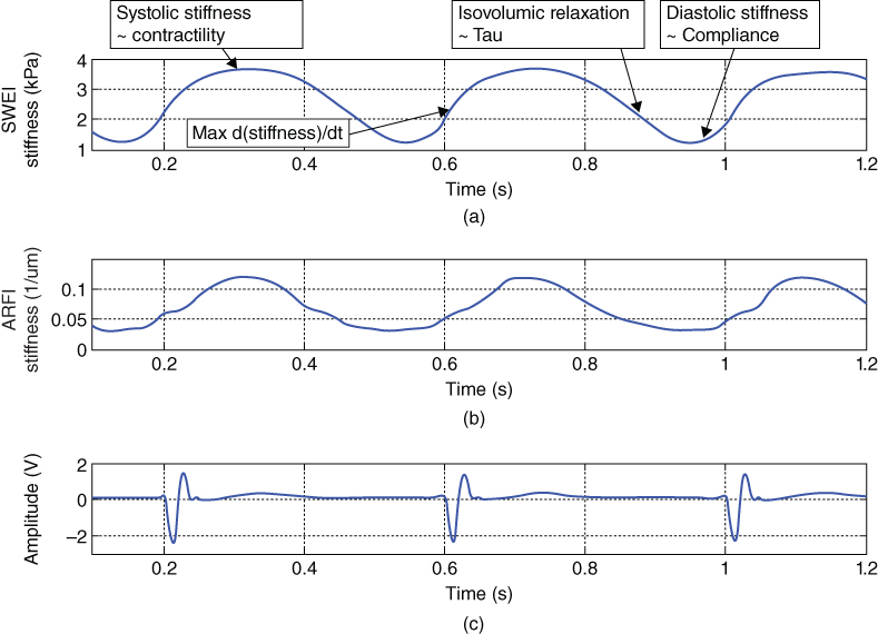
Figure 32.1 (a) SWEI and (b) ARFI stiffness measurements through the cardiac cycle respectively. SWEI measurements are shear modulus of stiffness and ARFI measurement are inverse displacement values (a measure of stiffness). (c) Simultaneous ECG signal. Note that cardiac stiffness increases during systole as the heart contracts and decreases during diastole when the heart is relaxed. The potential cardiac functional indices are marked on the SWEI measurements curve.
In 2007, Hsu et al. first used M‐mode and 2D ARFI imaging to evaluate the changes in myocardial stiffness through the cardiac cycle in an open chest canine heart model [7, 18]. Couade et al. measured the diastolic shear modulus at ∼2 kPa and the systolic shear modulus as ∼30 kPa using quantitative shear wave imaging methods [19].
Pernot et al. have studied contractility assessment using SWEI stiffness measurements in isolated rat hearts by recording systolic stiffness before and after administration of isoproterenol, an inotropic agent [20]. The myocardial stiffness and change in stiffness over time (d(stiffness)/dt max) increased significantly during systole and represented contractility. The measured myocardial stiffness also correlated strongly with isovolumic systolic pressure. In addition, the study reports significantly higher diastolic stiffness in hypertrophic rat hearts compared to a control group, suggesting shear wave imaging can quantify cardiac compliance. In another study in an in vivo large animal model, Pislaru et al. showed that measurements of passive myocardial elasticity quantified by a shear wave imaging method were correlated with elastic modulus and pressure‐segment length, an invasive measure of compliance [21].
In order to investigate the ability of SWEI to detect changes in compliance and contractility, Vejdani‐Jahromi et al. conducted experiments that used the known phenomena of the “Garden Hose effect” and “Gregg effect” respectively on isolated rabbit hearts [22]. It was shown that SWEI could detect the change in compliance due to the Garden Hose effect, the passive effect of coronary perfusion on cardiac compliance. The Gregg effect is the active effect of coronary perfusion on cardiac contractility. It was shown that SWEI could detect the increase in contractility corresponding to the increase in coronary perfusion shown by other methods in the literature. In addition, the Gregg effect was blocked by inhibiting Ca channels which resulted in a decrease in the contractility changes by coronary perfusion [23]. Figure 32.2 shows the effect of coronary perfusion pressure on cardiac contractility and compliance recorded by SWEI at different coronary perfusion pressure steps [23]. The potential of deriving relaxation time constant and systolic/diastolic ratio using ARFI imaging and SWEI techniques is also under investigation [24].

Figure 32.2 SWEI measurements of stiffness through cardiac cycle in an isolated rabbit heart. Myocardial stiffness increases in systole and diastole as the coronary perfusion is increased, corresponding to the known Gregg and Garden Hose effects. Systolic change is more prominent and is an active contractility change and diastolic change is less significant with a passive effect on compliance, as shown in the literature by pressure‐volume loop measurement. This is consistent with the SWEI stiffness recordings [23].
Considering the complicated nature of cardiac tissue, one can anticipate several factors that could affect elastography measurements of cardiac function. First of all, a linear, elastic, isotropic medium is assumed in the calculation of shear modulus of stiffness from the shear wave velocity or SWS [12]. However, it has been shown that cardiac tissue is a nonlinear, viscoelastic, and anisotropic medium. The previously mentioned work by Vejdani‐Jahromi et al. could imply the nonlinearity of cardiac tissue [22]. Researchers have utilized viscoelastic models to isolate elastic and viscous moduli of the cardiac tissue from each other [21, 25]. Therefore, it might be more practical if shear velocity is reported as the measure of stiffness rather than converting it to shear modulus using the above‐mentioned assumptions.
The quantitative measurements for ARFI imaging (displacement) and SWEI (SWS) are largely affected by anisotropy, particularly regarding the dependency of the shear wave propagation velocity on fiber orientation and the presence of heterogeneities [26, 27]. Myocardium is known to be highly anisotropic [28, 29] and shear waves propagate faster along fibers; without knowledge of local fiber orientation any quantitative measurements are of suspect value. A number of studies have examined the effect of anisotropy on SWEI measurements in the cardiac tissue and found significant effects of fiber orientation on SWEI shear wave velocity [19, 30, 31]. In addition, in an in vitro experiment Lee et al. showed that fiber angle could be mapped by rotating the transducer and finding the maximum SWS at each myocardial layer. Further developments using matrix probes could acquire and incorporate fiber orientation information into the elastic parameter calculations, thus improving the accuracy of the myocardial stiffness measurement.
Another issue to consider when calculating ARF‐induced SWS is the presence of Lamb‐Rayleigh waves, mechanical waves that propagate along the surface of a tissue. Lamb‐Rayleigh waves have different propagation properties than shear waves, and in ARF‐based imaging methods they are indistinguishable from shear waves and can affect the SWS calculation. Nonetheless, Nenadic et al. found that the velocity of Lamb‐Rayleigh waves is related to the shear wave velocity [32, 33].
Further studies are needed to characterize the relationship between ARFI imaging, SWEI‐derived local elasticity measurements, and global measurements of cardiac function, such as the pressure‐volume loop and relaxation time constants. Furthermore, the relationship between ARFI‐derived indices compared to SWEI should be studied in detail. Cardiac functional indices, including relaxation time constants measured by other techniques, need to be investigated and compared to the ones measured using ARF‐based methods. In summary, this is the first time in the history of cardiovascular research that a technique is able to detect the stiffness of cardiac tissue directly in vivo, and these methods have great potential for research and clinical applications in the field of cardiovascular research.
32.3.2 Clinical Translation of Transthoracic ARF‐based Methods for Cardiac Stiffness Assessment
As described in the previous section, imaging the stiffness of the heart with ultrasound has yielded highly encouraging results in ex vivo isolated heart preparations as well as open chest settings. While the above‐mentioned studies demonstrate the ability of cardiac elastography to provide novel information about myocardial function, its clinical applicability is contingent upon the ability to extract these functional indices through noninvasive means such as transthoracic imaging.
Transthoracic translation of ARFI and SWEI has been the topic of significant research by several groups over the last decade. Bradway et al. first demonstrated the ability of M‐mode ARFI to generate and track displacements in the interventricular septum through intercostal and subcostal imaging windows on porcine subjects [34]. They observed cyclic variations in displacement magnitude that corresponded to expected myocardial stiffness trends through the cardiac cycle based on the simultaneous ECG signal. In 2012, they also reported on the safety and feasibility of M‐mode ARFI in human subjects at varying levels of mechanical index (MI) at and above the FDA limit of 1.9 [35]. Their findings suggested that high MI sequences were thermally and mechanically safe for human use. While the use of higher MI resulted in larger tissue displacements in both cardiac phases, the ratio of diastolic to systolic displacements was relatively steady, suggesting that this ratio could be used as a radiation force‐independent metric of cardiac function. Most recently, Kakkad et al. reported on implementing M‐mode ARFI with harmonic tracking on a clinical ultrasound system to interrogate the stiffness of the interventricular septum through the cardiac cycle in parasternal long and short axis views within the FDA limits [36]. They measured diastolic to systolic displacement ratios in the range of 1.32 to 2.27 on human subjects. Figure 32.3 shows a transthoracic M‐mode ARFI acquisition.

Figure 32.3 Transthoracic M‐mode ARFI displacements in the interventricular septum measured through a parasternal long axis view. When compared with simultaneous ECG, the ARFI displacements show the expected cyclic pattern with high displacements in diastole (prior to P‐wave) and low displacements in systole (following the QRS complex).
Studies using transthoracic SWEI have primarily been limited to measuring stiffness of the myocardium at end diastole. Song et al. demonstrated improvements in the ability to track shear waves in vivo in the left ventricle through a short axis view with the use of pulse inversion harmonic tracking [37]. They measured mean end diastolic shear wave speeds of 1.56 m/s and saw successful shear wave propagation in 80% of acquisitions. They have further shown that improvements in success rates and shear wave signal quality can be made by tracking at higher frequencies using pediatric phased array transducers [38].
Even though transient elastography has shown promise for transthoracic applications, the results to date tend to have a large amount of variability associated with the derived indices of cardiac function. The cause of this variability has largely been attributed to three main challenges: (i) the difficulty in generating substantial displacements at depth, ii) the difficulty in accurately tracking induced displacements amidst ultrasonic clutter, and (iii) the difficulty in separating radiation force‐induced displacements from complex, multi‐dimensional intrinsic cardiac motion.
The first challenge can be addressed using high MI and/or longer push pulses. However the FDA currently limits the MI of all ultrasound applications to 1.9, and the use of longer pulses raises concerns about transducer and tissue heating. Stationary ultrasonic clutter is a routine issue in transthoracic imaging [39]. It not only degrades border detection and image quality but also adversely affects the accuracy of displacement tracking algorithms that are at the heart of ultrasound elastography [5]. The use of pulse inversion harmonic on tracking has been shown to improve the quality of displacement estimates for ARFI imaging [40] and SWEI [37]. Plane wave coherent compounding has also been shown to suppress clutter and improve displacement estimation [41]. Motion filtering has traditionally been performed after displacement estimation to remove axial components of tissue motion using linear or quadratic polynomial fit algorithms [6, 18]. However, the heart goes through complex motions, such as stretch, shear, and torsion, which need to be accounted for in order to better characterize its mechanical response to spatially confined impulsive excitations.
Given the inherent challenges posed by transthoracic imaging windows, transesophageal echocardiography (TEE) could provide a more viable alternative for the interrogation of cardiac elasticity. Transesophageal imaging would allow for lower clutter levels, better image quality, and shorter depths of penetration to the cardiac walls of interest at the expense of being a more intrusive procedure compared to transthoracic imaging. This avenue, while theoretically feasible, has yet to be explored in practice due to the limited availability of TEE probes capable of generating ARF excitation pulses.
Noninvasive measurement of cardiac stiffness through transthoracic imaging has great prognostic potential to diagnose a myriad of cardiomyopathies. Indices of cardiac function derived from transient elastography could be used to differentiate between systolic and diastolic heart failure, identify hypertrophy, assess transplant rejection, etc. Overcoming the challenges for these techniques could lead to a robust, real‐time tool with wide applications in general and interventional cardiology.
32.3.3 ARFI Imaging of Myocardial Ischemia and Infarct
ARFI and SWEI techniques have been explored as a means of characterizing damaged myocardium following an ischemic event. Couade et al. noted a reversible decrease in systolic shear wave speeds in response to temporary local ischemia induced by ligation in open‐chested sheep [19]. Hollender et al. used intracardiac ARFI and SWEI (M‐mode and 2D × time) to image pigs that had focal infarctions induced by coronary occlusion, finding local decreases in contractility months after the event and increased diastolic stiffness within the infarcted septum [42]. The same study noted the spatial heterogeneity of stiffness and contractility measurements, corresponding to the scattered locations of infarct confirmed with ex vivo MRI. The complexity of ischemic heart disease presents an opportunity for an ARFI‐based imaging system to have diagnostic impact, but requires a solution for reliably imaging the elasticity of large sections of myocardium with high spatial and temporal resolution throughout the cardiac cycle that is yet to be demonstrated.
32.4 ARF‐based Image Guidance for Cardiac Radiofrequency Ablation Procedures
Cardiac arrhythmias, heart rhythm disorders caused by fast, slow, or irregular heartbeats, affect millions patients each year. The most commonly diagnosed arrhythmia in clinical practice is atrial fibrillation (AF), which affects between 3 and 6 million people in the United States annually [1, 43]. Arrhythmias such as AF can arise due to a variety of factors (abnormal tissue, random firing), but most can be diagnosed with a comprehensive electrocardiography exam [43]. Nearly all cardiac arrhythmias can be managed with pharmaceutical intervention or palliatively treated with transcatheter ablation (TCA) [44]. Tens of thousands of TCA procedures are performed in the US annually, and diagnoses of AF are expected to more than double in the coming decades [1].
TCA aims to restore the normal rhythm of the heart by directly destroying or electrically isolating abnormally conducting myocardium with thermal radiofrequency ablation (RFA) lesions. To permanently stop the arrhythmia, the RFA lesions must extend the full depth of the myocardium (be transmural) and lesion lines must not have conductive gaps in between discrete lesions [45–47]. TCA procedures can be curative, but there is currently no clinically available method to directly visualize RFA lesions in the tissue; without a reliable way to assess lesion presence, size, and transmurality, post‐TCA arrhythmia recurrence is common and a significant number of patients (10–30%) require additional ablation procedures [48]. Ideally, direct visualization of the ablated region following RF delivery would provide feedback of RFA lesion presence and transmurality as well as lesion line continuity.
RF‐induced tissue heating creates a localized necrotic lesion that is stiffer than the surrounding myocardium. This change in viscoelasticity is due to the thermocoagulation and denaturation of the myocardium structural proteins (collagen [49], elastin) and myofilaments (myosin, actin [49–53]). Myocyte injury and tissue necrosis during thermal ablation are considered permanent and irreversible once protein thermocoagulation has occurred [50, 54], making relative tissue stiffness a useful measure for acutely differentiating a permanent lesion from healthy myocardium.
Eyerly et al. demonstrated that ARFI imaging could visualize the active stiffening process of the myocardium during thermal lesion formation in vitro [55]. It was found that the mean ARF‐induced displacements measured outside the lesion remained consistently high, but displacements decreased inside the pathological lesion during RF delivery. This finding confirmed that RF‐induced thermocoagulation actively stiffened the lesion site and that ARFI imaging could detect the change in relative tissue stiffness. It is important to note that in this case the stiffening was not due to immune‐fluid swelling or edema [56] as the preparation was in vitro.
In another in vitro experiment, Pernot et al. measured the increase in absolute tissue stiffness at RFA sites to be roughly twice that of the unablated tissue (unablated Young's modulus ∼27 kPa vs. ablated ∼54 kPa) using shear wave imaging methods [57]. Kwiecinski et al. similarly measured the increase in shear modulus at two‐ to five‐fold (22 ± 5 kPa unablated vs. 99 ± 17 kPa ablated) after ablation in vitro using shear wave elastography methods [58]. The accuracy of using ARFI imaging to determine RFA lesion size was investigated in vitro by Eyerly et al. [59]. This study determined that lesion dimensions from ARFI and pathology images were statistically similar, exhibiting borders within 1–2 mm.
32.4.1 Clinical Translation of ARFI Imaging for Acute Ablation Lesion Assessment
Translation of ARF‐based imaging methods for intraprocedure visualization of RFA lesions in an in vivo heart introduces five primary considerations: (1) the stiffness contrast of the lesion during the cardiac cycle, (2) the effects of bulk tissue motion on the displacement estimations, (3) transient physiological tissue stiffening processes, such as edema, that can affect the accuracy of the stiffness‐based lesion visualization, (4) imaging access, and (5) correlation of the elastography‐defined lesion with electrical block.
Acquiring ARFI images in diastole resolves considerations (1) and (2). As described in the cardiac function section, the myocardium is most compliant during diastole, and diastole‐gated ARFI imaging maximizes lesion contrast [57, 58, 60–62]. Figure 32.4 illustrates the relative stiffness difference between systole and diastole around a ventricular epicardial RFA lesion [60]. The lesion is visible as a semicircular region of relatively low ARFI‐induced displacement (dark blue). Using shear wave imaging, Kwiecinski et al. found absolute atrial stiffness was lowest during diastole (R‐wave) for both unablated and ablated myocardium [58]. Also, late diastole is the time of least intrinsic motion during the cardiac cycle and reduces the effects of bulk cardiac motion on the tissue displacement measurements. It has been shown that bulk cardiac motion can be effectively managed with post‐processing “motion‐filter” techniques [6]. Overall, diastole gated ARFI imaging provides the highest contrast between any stiff lesions and the surrounding myocardium, but this approach limits the acquisition frame rate to one image per heartbeat.

Figure 32.4 ARFI images of a right ventricular epicardial RFA lesion through the cardiac cycle. A nonirrigated electrode tip ablated the epicardial surface (EPI = epicardium, ENDO = endocardium) for 7 s at 20 W. (a) ARFI images acquired at different times during the cardiac cycle: (1) and (4) during diastole, (2) during systole, and (3) during end‐systole. ARFI images were acquired with a linear transthoracic probe vacuum suctioned to the RV epicardium. Color bar units are maximum displacement away from the transducer in microns. Within the lesion, the ARFI‐induced displacement is low throughout the cycle. The normal myocardium cycles between high displacement during diastole and low displacement during systole. (b) ARFI acquisition times corresponding to the ECG. Source: reprinted from [60], Copyright 2012, with permission from Elsevier.
While in vitro work demonstrated the ability of ARFI imaging to visualize thermocoagulated lesions, the myocardium surrounding the pathological lesion in vivo can be temporarily affected by the diffusive hyperthermia immediately following ablation [63–65]. This “border” zone is characterized by injured or “stunned” myocytes that suffer a temporary loss of cellular excitability and immune‐fluid infiltration or edema [56, 63–65]. A study by Grondin et al. measured an increase in tissue stiffness (decrease in strain) at RFA sites in human patients using strain‐imaging methods [66]. In three patients, they reported that the average of the absolute strain measurements decreased from 16.2 ± 17.7% to 10.0 ± 10.7% when re‐measuring the strain of the ablation site at a later time step (5 to 20 minutes). These results suggested there was a stiffening of the tissue at the ablation site in the peri‐ablation period; the stiffening could have been due to a hydrostatic pressure increase from acute transient edema at the thermal injury site that was large enough to increase the local tissue stiffness. Therefore to address consideration (3), Eyerly et al. characterized the spatial and temporal stability of the lesion, or region of stiffness increase (RoSI), in the peri‐ablation period in vivo [48]. In six canine subjects, SWEI measurements and 2D ARFI images were acquired at six ventricular endocardial RFA sites before, during, and for 30 minutes post ablation. The imaging transducer was placed on the epicardial surface and the imaging plane penetrated inward while the ablation catheter and RFA was applied inside on the endocardial surface; the ablation catheter blocks the ARF excitation and this way the catheter was below the tissue being evaluated with ARFI imaging. In this setup, an immediate increase in tissue stiffness was detected during RFA, and the area of the RoSI as well as the relative stiffness at the RoSI center were stable approximately 2 minutes after ablation. Of note is the observation that relative stiffness in the region adjacent to the RoSI increased slightly in the first 15 minutes after ablation, consistent with local fluid displacement or edema. The magnitude of this increase, ∼0.5‐fold from baseline, was significantly less than the magnitude of the stiffness increase directly inside the RoSI, which was greater than 3‐fold from baseline.
To translate ARF‐based imaging techniques for clinical use in the hearts of human patients during TCA procedures, ARFI imaging and shear wave imaging methods were developed on intracardiac echocardiography (ICE) platforms [42, 58, 61, 62, 67]. ICE is clinically performed with a phased‐array ultrasound transducer on an 8‐10 French catheter, and during TCA provides real‐time visualization of the cardiac anatomy and function from within the cardiac chambers [68–71]. ICE is an indispensable tool for guiding safe and accurate trans‐septal punctures for left atrial (LA) access [68, 71–73] during ablation procedures and is often used for visualizing catheter placement and tissue contact for effective RF delivery.
Fahey et al. in 2005 and Hsu et al. in 2007 [61, 62] conducted preliminary in vivo feasibility studies of ICE‐ARFI imaging in a canine model; they observed an increase in tissue stiffness at three endocardial RFA sites, evident by a decrease in the measured ARFI‐induced displacement [62]. This work also described the challenges encountered when implementing ARFI imaging from an ICE catheter in vivo [62]. For example, it was discovered that the flexible transducer tip experienced a small rebound force, or “kick‐back” from the generation of the ARFI excitations that is then measured along with the tissue‐displacement response. Kwiecinski et al. reported a similar phenomenon when using ICE‐based shear wave elastography [58]. Methods to minimize the effect of this kick‐back on the data, such as adding “priming‐pulses” to pre‐load the imaging catheter before the tissue‐excitation sequence [62], are being used and more sophisticated methods are under investigation. Additional challenges related to maximizing the energy delivery and the uniformity of the energy across the field of view were also described by Hsu et al. [62]. Their investigation suggested the ICE catheter be positioned at an imaging focal depth within 2 cm of the endocardium and as parallel to the transducer face as possible; this maximizes the induced displacement (contrast) and minimizes depth‐dependent energy delivery to the tissue [9, 62, 74].
Eyerly et al. integrated the ICE‐ARFI imaging techniques developed by Fahey et al. and Hsu et al. with an electroanatomical mapping (EAM) system, and used the combined system to precisely gather ARFI images of RFA lesions during TCA procedures in canine subjects [60, 75]. Readers of the ARFI images identified stiff lesion locations with high specificity and sensitivity and found that average measured displacements were lower in ablated myocardium (6.06 ± 0.94 µm) than unablated (11.23 ± 1.71 µm) myocardium; average lesion contrast was 0.29 ± 0.33 and the contrast to noise was 1.83 ± 1.75 [75]. Similarly, Kwiecinski et al. found a SWS increase ratio of 1.8 ± 0.3 from unablated to ablated with ICE‐based shear wave imaging in a preclinical study in sheep [58].
To be a clinically relevant method for lesion evaluation during TCA, the stiffness‐identified lesions in the ARFI images must also correlate with the electrical substrate modification or electrical block at the ablation site. Eyerly et al. conducted an experiment that showed ICE‐ARFI imaging was able to identify lesions that correlated with the electrical destruction of the tissue [60]. Using the integrated ICE‐ARFI imaging and EAM system, in eight canine subjects reviewers of the ARFI images identified conduction‐disturbing RFA‐treated sites with high sensitivity (95.7%) and specificity (91.5%). Identification of contiguous lesion sets or complete electrical block based on the ARFI images had 75.3% specificity and 47.1% sensitivity. An example from this study is shown in Figure 32.5. Before RFA the myocardial elasticity is homogeneous with relatively high ARFI‐induced displacements (Figure 32.5, part 1C) and electrical propagation, represented by the color gradient, is smooth and uninhibited (Figure 32.5, part 1A). When a conductive unablated gap was left in the lesion line (Figure 32.5, part 2A), this is visible as the area of high tissue displacement (>7.5 µm) surrounded by areas of relatively low tissue displacements (<4.5 µm) in the ARFI image (Figure 32.5, part 2C). The final ARFI image shows a homogeneous region of low displacement (Figure 32.5, part 3C) correlating with the line of conduction block (Figure 32.5, part 3A), confirming complete ablation of the gap. This study also highlighted the necessity of the EAM system to guide the 2D ARFI imaging plane for efficient imaging of the RFA targets. Further development of 3D ARFI imaging methods[76] would be necessary to make ARFI a standalone tool for lesion assessment.

Figure 32.5 An example of three ARFI image‐EAM map pairs. Row 1: acquired before RFA. Row 2: acquired after intentionally creating a 1 cm conductive gap. Row 3: acquired after closure of the 1 cm gap. Column A: electrical maps showing the imaging fan position in the canine right atrium and the location of delivered RFA lesions (red spherical markers). Column B: conventional B‐mode images acquired at the location indicated on the LAT maps. There is no lesion visible in the B‐mode images. Column C: maximum ARFI‐induced displacement images. The color bar units are microns of tissue displacement away from the transducer. RFA lesion sites are visible as regions of lower relative displacement (stiffer tissue). Source: reprinted from [60], copyright 2012, with permission from Elsevier.
32.4.2 Preliminary Clinical Investigations of ARFI Imaging of Ablation Lesions
The preclinical work presented in the previous section demonstrated ARF imaging methods could visualize the relative stiffness difference between untreated myocardium and RFA lesions in vivo and that the stiff lesions created electrical propagation modifications. Based on these findings, a pilot clinical study by Bahnson et al. was undertaken to investigate the feasibility of intraprocedure RFA lesion evaluation with ARFI imaging in human patients [77]. In this study, intraprocedure ICE‐ARFI images successfully identified acute RFA lesions in common ablation targets in the human heart, and ARFI imaging identified a ∼47% reduction in the relative stiffness at RFA sites. This finding is similar to the difference between the increases in stiffness seen in the previously mentioned studies. An example image from this study is shown in Figure 32.6; the figure depicts ARFI imaging of sequential RFA sites at the LA roof of a patient undergoing TCA for AF. Tissue stiffening, relative to adjacent unablated tissue in the field of view, is produced by the sequential application of RF energy. The initial ablation near the left of each panel produced tissue stiffening that was reproducibly imaged over a period of the several minutes.

Figure 32.6 ICE and ARFI images of the ablation catheter contact location (red arrows, row A) for three consecutive RF applications (irrigated, 35 W power‐controlled, 60 s each) at the LA roof. White arrows indicate the newly formed regions of increased tissue stiffness after RFA. The position and orientation of the ICE catheter was maintained between acquisitions, but note that the ARFI imaging plane in B1 was steered (an operator capability included on the clinical software platform) slightly to the right compared to panels B2 and B3 to keep the ablation catheter out of the field of view during ARFI imaging of B1. The color bar units are microns of tissue displacement away from the transducer. Source: reprinted from [77], copyright 2012, with permission from John Wiley and Sons.
Based on the success of preclinical results and preliminary clinical trials, further investigation of ARFI imaging for intraprocedure ablation lesion assessment is underway. Improvements in imaging technology, image sequencing, and scanner and catheter hardware would greatly increase the chances of this technology being successfully integrated into clinical TCA procedures. Opportunities also exist for elastography‐based assessment of chronic lesions and endogenous atrial scar tissue characterization for improving TCA treatment strategies [78]. If successfully translated for clinical use, elastography‐based lesion assessment could improve the accuracy and safety of TCA procedures with minimal modifications to current procedure methods and equipment.
32.5 Conclusions
ARF‐based elastography techniques have recently been under investigation for cardiac imaging applications. ARF‐based imaging methods offer a myriad of opportunities for the diagnosis and treatment of various cardiac diseases as it provides previously unavailable information on the local dynamic stiffness characteristics of tissue. The content in this chapter presents the encouraging results encountered in our research into cardiac ARF‐based elastography. Also, both ARFI imaging and SWEI techniques can be implemented on conventional ultrasound scanners and probes, thus providing a portable and cost‐efficient imaging modality for cardiac imaging. These promising results highlight the many opportunities to improve and refine ARFI imaging and SWEI techniques for cardiac applications.
Funding Acknowledgements
NIH grant numbers R01‐EB‐012484 and R37‐HL‐096023.
References
- 1 Mozaffarian, D., et al. (2015). Heart disease and stroke statistics – 2015 update: a report from the American Heart Association. Circulation 131 (4): e29–322.
- 2 Doherty, J.R., et al. (2013). Acoustic radiation force elasticity imaging in diagnostic ultrasound. IEEE Trans. Ultrason., Ferroelectr., Freq . Control 60 (4): 685–701.
- 3 Nightingale, K. (2011). Acoustic radiation force impulse (ARFI) imaging: a review. Curr. Med. Imaging Rev. 7 (4): 328–339.
- 4 Palmeri, M.L. and Nightingale, K.R. (2011). Acoustic radiation force‐based elasticity imaging methods. Interface Focus 1 (4): 553–564.
- 5 Pinton, G.F., Dahl, J.J., and Trahey, G.E. (2006). Rapid tracking of small displacements with ultrasound. IEEE Trans. Ultrason., Ferroelect., Freq . Control 53 (6): 1103–1117.
- 6 Giannantonio, D.M., Dumont, D.M., Trahey, G.E., and Byram, B.C. (2011). Comparison of physiological motion filters for cardiac ARFI. Ultrason. Imaging 33 (2): 89–108.
- 7 Hsu, S.J., et al. (2009). Novel acoustic radiation force impulse imaging methods for visualization of rapidly moving tissue. Ultrason. Imaging 31 (3): 183–200.
- 8 Nightingale, K., et al. (2005). Ultrasonic imaging of the mechanical properties of tissues using localized, transient acoustic radiation force. In: 2005 IEEE International Conference on Acoustics, Speech, and Signal Processing, Vols 1–5, 981–984.
- 9 Palmeri, M.L., et al. (2005). A finite‐element method model of soft tissue response to impulsive acoustic radiation force. IEEE Trans. Ultrason., Ferroelect., Freq . Control 52 (10): 1699–1712.
- 10 Nightingale, K.R., et al. (2011). Comparison of qualitative and quantitative acoustic radiation force based elasticity imaging methods. In: 2011 8th IEEE International Symposium on Biomedical Imaging: From Nano to Macro, 1606–1609.
- 11 Nightingale, K., McAleavey, S., and Trahey, G. (2003). Shear‐wave generation using acoustic radiation force: in vivo and ex vivo results. Ultrasound Med . Biol. 29 (12): 1715–1723.
- 12 Sarvazyan, A.P., et al. (1998). Shear wave elasticity imaging: a new ultrasonic technology of medical diagnostics. Ultrasound Med . Biol. 24 (9): 1419–1435.
- 13 Hollender, P.J., et al. (2015). Single‐ and multiple‐track‐location shear wave and acoustic radiation force impulse imaging: matched comparison of contrast, contrast‐to‐noise ratio and resolution. Ultrasound Med . Biol. 41 (4): 1043–1057.
- 14 Palmeri, M.L. and Nightingale, K.R. (2011). What challenges must be overcome before ultrasound elasticity imaging is ready for the clinic? Imaging Med. 3 (4): 433–444.
- 15 Burkhoff, D., Mirsky, I., and Suga, H. (2005). Assessment of systolic and diastolic ventricular properties via pressure‐volume analysis: a guide for clinical, translational, and basic researchers. Am. J. Physiol. Heart Circ. Physiol. 289 (2): H501–512.
- 16 D'Hooge, J., Herbots, L., and Sutherland, G.R. (2003). Quantitative assessment of intrinsic regional myocardial deformation by Doppler strain rate echocardiography in humans. Circulation 107 (7): e49; author reply e49.
- 17 Urheim, S., et al. (2000). Myocardial strain by Doppler echocardiography. Validation of a new method to quantify regional myocardial function. Circulation 102 (10): 1158–1164.
- 18 Hsu, S.J., et al. (2007). In vivo assessment of myocardial stiffness with acoustic radiation force impulse imaging. Ultrasound Med . Biol. 33 (11): 1706–1719.
- 19 Couade, M., et al. (2011). In vivo quantitative mapping of myocardial stiffening and transmural anisotropy during the cardiac cycle. IEEE Trans. Med. Imaging 30 (2): 295–305.
- 20 Pernot, M., et al. (2011). Real‐time assessment of myocardial contractility using shear wave imaging. J. Am. Coll. Cardiol. 58 (1): 65–72.
- 21 Pislaru, C., et al. (2014). Viscoelastic properties of normal and infarcted myocardium measured by a multifrequency shear wave method: comparison with pressure‐segment length method. Ultrasound Med . Biol. 40 (8): 1785–1795.
- 22 Vejdani‐Jahromi, M., et al. (2015). Ultrasound shear wave elasticity imaging quantifies coronary perfusion pressure effect on cardiac compliance. IEEE Trans. Med. Imaging 34 (2): 465–473.
- 23 Vejdani‐Jahromi, M., Freedman, J., Nagle, M., et al. (2016). Quantifying myocardial contractility changes using ultrasound‐based shear wave elastography. J. Am. Soc. Echocardiogr. 30 (1): 90–96.
- 24 Vejdani‐Jahromi, M., Nagle, M., Jiang, Y., et al. (2016). A comparison of acoustic radiation force derived indices of cardiac function in the Langendorff perfused rabbit heart. IEEE Trans. Ultrason., Ferroelectr., Freq . Control, March 2016. 63 (9): 1288–1295.
- 25 Amador, C., et al. (2012). Loss tangent and complex modulus estimated by acoustic radiation force creep and shear wave dispersion. Phys. Med. Biol. 57 (5): 1263–1282.
- 26 Wang, M., et al. (2013). Imaging transverse isotropic properties of muscle by monitoring acoustic radiation force induced shear waves using a 2‐D matrix ultrasound array. IEEE Trans. Med. Imaging 32 (9): 1671–1684.
- 27 Rouze, N.C., et al. (2012). Parameters affecting the resolution and accuracy of 2‐D quantitative shear wave images. IEEE Trans. Ultrason., Ferroelectr., Freq . Control 59 (8): 1729–1740.
- 28 Helm, P.A., et al. (2005). Ex vivo 3D diffusion tensor imaging and quantification of cardiac laminar structure. Magn. Reson. Med. 54 (4): 850–859.
- 29 Streeter, D.D., Jr., et al. (1969). Fiber orientation in the canine left ventricle during diastole and systole. Circ. Res. 24 (3): 339–347.
- 30 Bouchard, R.R. (2010). Acoustic radiation force impulse‐driven shear wave velocimetry in cardiac tissue. Ph.D. Thesis from Department of Biomedical Engineering, Duke University, Durham, NC, USA.
- 31 Lee, W.N., et al. (2012). Mapping myocardial fiber orientation using echocardiography‐based shear wave imaging. IEEE Trans. Med. Imaging 31 (3): 554–562.
- 32 Nenadic, I.Z., et al. (2011). Lamb wave dispersion ultrasound vibrometry (LDUV) method for quantifying mechanical properties of viscoelastic solids. Phys. Med. Biol. 56 (7): 2245–2264.
- 33 Nenadic, I.Z., et al. (2011). Phase velocities and attenuations of shear, Lamb, and Rayleigh waves in plate‐like tissues submerged in a fluid (L). J. Acoust. Soc. Am. 130 (6): 3549–3552.
- 34 Bradway, D.P., et al. (2007). 6B‐6 Transthoracic cardiac acoustic radiation force impulse imaging: a feasibility study. In: IEEE Ultrasonics Symposium, 2007.
- 35 Bradway, D.P., et al. (2012). Feasibility and safety of transthoracic cardiac acoustic radiation force impulse imaging methods. In: IEEE International Ultrasonics Symposium (IUS), 2012.
- 36 Kakkad, V., et al. (2015). In vivo transthoracic measurements of acoustic radiation force induced displacements in the heart over the cardiac cycle. In: IEEE International Ultrasonics Symposium (IUS), 2015.
- 37 Song, P., et al. (2013). Improved shear wave motion detection using pulse‐inversion harmonic imaging with a phased array transducer. IEEE Trans. Med. Imaging 32 (12): 2299–2310.
- 38 Pengfei, S., et al. (2015). Implementation of shear wave elastography on pediatric cardiac transducers with pulse‐inversion harmonic imaging and time‐aligned sequential tracking. In: IEEE International Ultrasonics Symposium (IUS), 2015.
- 39 Zwirn, G. and Akselrod, S. (2006). Stationary clutter rejection in echocardiography. Ultrasound Med . Biol. 32 (1): 43–52.
- 40 Doherty, J.R., Dahl, J.J., and Trahey, G.E. (2013). Harmonic tracking of acoustic radiation force‐induced displacements. IEEE Trans. Ultrason., Ferroelectr., Freq . Control 60 (11): 2347–2358.
- 41 Papadacci, C., et al. (2014). High‐contrast ultrafast imaging of the heart. IEEE Trans. Ultrason., Ferroelectr., Freq . Control 61 (2): 288–301.
- 42 Hollender, P.J., et al. (2012). Intracardiac echocardiography measurement of dynamic myocardial stiffness with shear wave velocimetry. Ultrasound Med . Biol. 38 (7): 1271–1283.
- 43 Calkins, H., et al. (2012). 2012 HRS/EHRA/ECAS expert consensus statement on catheter and surgical ablation of atrial fibrillation: recommendations for patient selection, procedural techniques, patient management and follow‐up, definitions, endpoints, and research trial design. Heart Rhythm 9 (4): 632–696 e21.
- 44 Cappato, R., et al. (2010). Updated worldwide survey on the methods, efficacy, and safety of catheter ablation for human atrial fibrillation. Circ. Arrhythm. Electrophysiol. 3 (1): 32–38.
- 45 Kowalski, M., et al. (2012). Histopathologic characterization of chronic radiofrequency ablation lesions for pulmonary vein isolation. J. Am. Coll. Cardiol. 59 (10): 930–938.
- 46 Ranjan, R., et al. (2011). Gaps in the ablation line as a potential cause of recovery from electrical isolation and their visualization using MRI. Circ. Arrhythm. Electrophysiol. 4 (3): 279–286.
- 47 Miller, M.A., et al. (2012). Acute electrical isolation is a necessary but insufficient endpoint for achieving durable PV isolation: the importance of closing the visual gap. Europace 14 (5): 653–660.
- 48 Eyerly, S.A., Vejdani‐Jahromi, M., Dumont, D.M., et al. (2015). The evolution of tissue stiffness at radiofrequency ablation sites during lesion formation and in the peri‐ablation period. J. Cardiovasc. Electrophysiol. 26 (9): 1009–1018.
- 49 Wright, N.T. and Humphrey, J.D. (2002). Denaturation of collagen via heating: an irreversible rate process. Annu. Rev. Biomed. Eng. 4 : 109–128.
- 50 Bischof, J.C. and He, X. (2005). Thermal stability of proteins. Ann. NY Acad. Sci. 1066: 12–33.
- 51 Chen, S.S. and Humphrey, J.D. (1998). Heat‐induced changes in the mechanics of a collagenous tissue: pseudoelastic behavior at 37 degrees C. J. Biomech. 31 (3): 211–216.
- 52 Wu, T., et al. (2001). Assessment of thermal tissue ablation with MR elastography. Magn. Reson. Med. 45 (1): 80–87.
- 53 Pearce, J.A. (2010). Models for thermal damage in tissues: processes and applications. Crit. Rev. Biomed. Eng. 38 (1): 1–20.
- 54 Lepock, J.R. (2003). Cellular effects of hyperthermia: relevance to the minimum dose for thermal damage. Int. J. Hyperthermia 19 (3): 252–266.
- 55 Eyerly, S.A., et al. (2013). In vitro monitoring of the dynamic elasticity changes during radiofrequency ablation with acoustic radiation force impulse imaging. J. Cardiovasc. Electrophysiol. 24 (4): 472–473.
- 56 Schwartzman, D., et al. (2001). Cardiac swelling associated with linear radiofrequency ablation in the atrium. J. Interv. Card. Electrophysiol. 5 (2): 159–166.
- 57 Pernot, M., et al. (2009). Mapping myocardial elasticity changes after RF‐ablation using supersonic shear imaging. Comput. Cardiol. 793–796.
- 58 Kwiecinski, W., et al. (2014). Quantitative evaluation of atrial radio frequency ablation using intracardiac shear‐wave elastography. Med. Phys. 41 (11): 112901.
- 59 Eyerly, S.A., et al. (2010). An in vitro assessment of acoustic radiation force impulse imaging for visualizing cardiac radiofrequency ablation lesions. J. Cardiovasc. Electrophysiol. 21 (5): 557–563.
- 60 Eyerly, S.A., et al. (2012). Intracardiac acoustic radiation force impulse imaging: a novel imaging method for intraprocedural evaluation of radiofrequency ablation lesions. Heart Rhythm 9 (11): 1855–1862.
- 61 Fahey, B.J., et al. (2005). Acoustic radiation force impulse imaging of myocardial radiofrequency ablation: initial in vivo results. IEEE Trans. Ultrason., Ferroelect., Freq . Control 52 (4): 631–641.
- 62 Hsu, S.J., et al. (2007). Challenges and implementation of radiation‐force imaging with an intracardiac ultrasound transducer. IEEE Trans. Ultrason., Ferroelect., Freq . Control 54 (5): 996–1009.
- 63 Nath, S., et al. (1993). Cellular electrophysiological effects of hyperthermia on isolated guinea pig papillary muscle. Implications for catheter ablation. Circulation 88 (4, part 1): 1826–1831.
- 64 Wilber, D.J., Packer, D., and Stevenson, W.G. (2008). Catheter Ablation of Cardiac Arrhythmias : Basic Concepts and Clinical Applications, 3rd edn., Malden, Mass.: Blackwell Futura.
- 65 Ge, Y.Z., et al. (1995). Cellular electrophysiological changes induced in vitro by radiofrequency current: comparison with electrical ablation. Pacing Clin. Electrophysiol. 18 (2): 323–333.
- 66 Grondin, J., et al. (2015). Intracardiac myocardial elastography in canines and humans in vivo. IEEE Trans. Ultrason., Ferroelectr., Freq . Control 62 (2): 337–349.
- 67 Hsu, S.J., et al. (2008). Intracardiac echocardiography and acoustic radiation force impulse imaging of a dynamic ex vivo ovine heart model. Ultrason. Imaging 30 (2): 63–77.
- 68 Ruisi, C.P., Brysiewicz, N., Asnes, J.D., et al. (2013). Use of intracardiac echocardiography during atrial fibrillation ablation. Pacing Clin. Electrophysiol. 36: 781–788.
- 69 Proulx, T.L., Tasker, D., and Bartlett‐Roberto, J. (2005). Advances in catheter‐based ultrasound imaging: Intracardiac Echocardiography and the ACUSON AcuNavTM. Ultrasound Catheter 1: 669–678.
- 70 Natale, A. (2006). Intracardiac Echocardiography in Interventional Electrophysiology. Abingdon UK: Informa Healthcare.
- 71 Robinson, M.R. and Hutchinson, M.D. (2010). Use of imaging techniques to guide catheter ablation procedures. Curr. Cardiol. Rep. 12 (5): 374–381.
- 72 Earley, M.J. (2009). How to perform a transseptal puncture. Heart 95 (1): 85–92.
- 73 Yamada, T., et al. (2007). One‐puncture, double‐transseptal catheterization manoeuvre in the catheter ablation of atrial fibrillation. Europace 9 (7): 487–489.
- 74 Nightingale, K., Palmeri, M., and Trahey, G. (2006). Analysis of contrast in images generated with transient acoustic radiation force. Ultrasound Med . Biol. 32 (1): 61–72.
- 75 Eyerly, S.A., et al. (2014). Contrast in intracardiac acoustic radiation force impulse images of radiofrequency ablation lesions. Ultrason. Imaging 36 (2): 133–148.
- 76 Hollender, P., et al. (2013). Three‐dimensional fusion of shear wave imaging and electro‐anatomical mapping for intracardiac radiofrequency ablation monitoring. In: IEEE International Ultrasonics Symposium (IUS) , 2013 108–111.
- 77 Bahnson, T.D., et al. (2014). Feasibility of near real‐time lesion assessment during radiofrequency catheter ablation in humans using acoustic radiation force impulse imaging. J. Cardiovasc. Electrophysiol. 25 (12): 1275–1283.