CHAPTER 11. Network Attached Storage (NAS) and Storage Area Networks (SANs)
SOME OF THE MAIN TOPICS IN THIS CHAPTER ARE
Local Versus Networked Storage Devices 165
Basic SANs: Arbitrated Loops 172
Using a Fabric Switched Topology for SANs 176
A Mixed Topology of Loops and Switches 178
What Kind of NAS or SAN Solution Should You Use? 182
All the components that make up a computer, from the CPU to memory, the bus, and others, are rapidly expanding in speed and capacity and probably will continue to do so for many years to come. One area of computer technology that while continuing to evolve is doing so at a somewhat slower pace is storage devices attached directly, such as disk and tape drives. For desktop workstations that use limited storage, this is not really a problem. For servers that offer file services to other computers, this is a serious issue with which administrators must contend. As the need for storage continues to grow, it is pushing the limits of the most typical server storage interface today: the SCSI (Small Computer Systems Interface) interface. And because most large servers use RAID arrays, even more disks are needed to store data due to the mechanics of disk mirroring, striping, and so on.
The SCSI parallel architecture, using multiple wires and intricate clocking, can work only over short distances. The different levels of SCSI that exist today have different distance limitations as well as limitations as to the number of devices that can be attached to a SCSI cable. Because of these physical limitations, it is apparent that eventually you will run out of PCI slots to hold SCSI cards, and that all the storage you can fit within the limits of the current SCSI capabilities will be exhausted, as shown in Table 11.1.
Table 11.1. SCSI Types and Capabilities
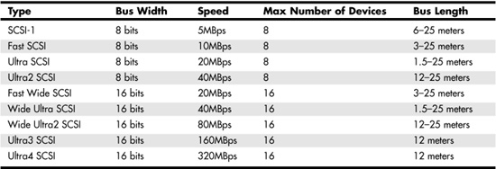
One practical solution would be to get another server and divide the chores. But for some very large servers (or clusters) that provide Internet services, or other applications that require a large amount of storage, the physical SCSI architecture is now seeing its last days. You can only connect so much storage to a server, given the distance limitations of SCSI technologies and higher disk capacities. Eventually, disk storage space that you can connect to a server will become finite, and a bottleneck. Thus, parallel SCSI does have limitations. The new Serial Attached SCSI (SAS) standard, which combines compatibility with Serial ATA (SATA) hard disks with the management features and performance of SCSI, is expected to eventually replace parallel SCSI implementations at the server level.
![]() For more information about SAS, see Chapter 7 of the book Upgrading and Repairing Servers.
For more information about SAS, see Chapter 7 of the book Upgrading and Repairing Servers.
Newer technologies are needed in just a few years to satisfy the need for growing, reliable storage. One is the emerging InfiniBand technology, and the other is the proliferation of Storage Area Networks (SANs).
As enterprise data begins to be measured in terabytes now instead of gigabytes, there simply must be a better way to make data available to one or more large network servers. Currently, that method—especially for large networks in which downtime is very rarely tolerated—is the Storage Area Network (SAN). Another method of expanding data storage by using networking technology—often used in small to mid-sized network environments—is the Network Attached Storage (NAS) device (sometimes called a network appliance), which you will also learn about in this chapter.
NAS devices are attached to a LAN along with client and server computers. SANs are usually connected to the larger servers using a separate network. There are exceptions to this rule, of course. Some enterprise networks still use NAS because it was “there first.” There is no need to replace what works with a more expensive technology just because it exists. In this chapter you will find compelling reasons for using NAS, SANs, or possibly both in your network, depending on your requirements. Both of these technologies have specific features that make them useful in different environments. You will find that some networks can make use of both technologies, again, depending on the data requirements for the network.
First, let’s examine the most widely used technology for attaching storage devices to a server: the Small Computer Systems Interface (SCSI). We’ll also cover the limitations of this legacy technology in large enterprise networks.
Local Versus Networked Storage Devices
Both SCSI cards and network adapter cards connect to the PCI bus in your computer, but the similarity ends there. The network card uses a serial communications method (using two wires in most cases—for send and receive for modern Ethernet networks).
![]() You can learn more about traditional Ethernet network adapters by reading Chapter 7, “Network Interface Cards.”
You can learn more about traditional Ethernet network adapters by reading Chapter 7, “Network Interface Cards.”
SCSI uses a parallel method, involving many wires (the number varies according to the SCSI specification). Serial communications techniques can be used to cover greater distances than parallel methods. That is why simple Ethernet networks can span much larger distances than can the locally attached SCSI devices for a server.
Today there are many versions of SCSI—more than the number of different cables used to make connections between SCSI devices (or controllers of these devices) and the PCI cards that provide the link between the server and storage. For more information on the different types of SCSI and its eventual replacement, SAS, check out Upgrading and Repairing Servers.
Note
The SCSI parallel interface was first used by Apple Computers, and you will still find it in use for some Apple products. Just like FireWire (which was also developed by Apple), these advanced technologies have been adopted by the Intel community, and have also been adopted as specifications by the IEEE. Now Intel-based computers running Windows or Linux can easily support both of these protocols. Keep in mind, however, that these technologies do not provide the distance that Fibre Channel or IP SANs can provide, using their respective technologies.
Using fiber-optic cabling, serial communications can cover very large distances, and allow fast access to a network composed of many devices.
Just as a LAN can be used to allow a server to provide storage file shares to client workstations, there are two other major types of networked storage that can overcome the distance limitations imposed by SCSI devices: Network Attached Storage and Storage Area Networks.
Defining Network Attached Storage (NAS)
One way to attach additional storage is to place the storage itself on the network for the server or clients to access. This technique is called Network Attached Storage (NAS), because it shares the same network as the clients. When the storage device (such as a disk array or tape drive, or a mixture of both in the same box) is accessed, the data transfer occurs on the same LAN as your clients and servers. Thus, if your network is already experiencing heavy utilization, using NAS may further cause degradation in network performance. In a small network, such as in a SOHO setting or a small department that needs local access to a small number of files, a NAS device can be a perfect fit, especially if the majority of communications are between the NAS device and servers or clients of the local LAN segment. Yet if a large amount of network traffic is sent between servers or clients on the LAN, the NAS device can severely impact the bandwidth on the LAN. All of this is, of course, because the servers, clients, and NAS devices share the same network. This is one of the major differences between Network Attached Storage and Storage Area Networks. The latter option uses a separate network and does not cause any bandwidth degradation on the LAN.
For much larger networks, which use hundreds of servers and many thousands of clients, the choice between NAS and SANs is a little different. Because SANs reside on a network separate from the production network, data transfers between the server and storage can be greatly increased.
Defining a Storage Area Network (SAN)
Storage Area Networks (SANs) are similar to NAS in topology, with the exception that a SAN is made up of devices on a network that is not the same network used for the LAN. Figure 11.1 shows the basic difference between NAS and SANs.
Figure 11.1. NAS and SANs use different network topologies.
The NAS-based network, shown on the left side of Figure 11.1, has network clients and servers as well as NAS devices attached to the LAN. The file server uses the same LAN to service client requests as it uses to get data from NAS devices. In many cases, it is possible to configure NAS devices to work as if they are servers, and the most popular disk formats are supported on the main players in this market. In a switched environment as shown in Figure 11.1, traffic will be minimized somewhat due to the switches involved. However, the single network adapter card on the file server is a bottleneck. You could put in another NIC and use it to attach to the NAS devices. This would be similar to the Storage Area Network (SAN) shown on the right side of Figure 11.1.
In the SAN, a typical NIC attaches the file server to the LAN. A separate card called a host bus adapter is used to connect the file server to a Fibre Channel–based SAN. Communications with devices on the SAN do not cause any traffic on the network’s LAN. These examples are simplified explanations of most installed NAS and SAN networks, but however complex the design, the basics remain the same.
Network Attached Storage
As an alternative to SANs, especially for smaller networks, consider Network Attached Storage (NAS). NAS technology is now available for all levels of networks, including SOHO networks.
NAS has some advantages over SAN technology. Consequently, in some situations it may be a better solution for your network storage needs:
![]() Your network traffic on the LAN is minimal and the impact of one or more NAS servers will not affect performance greatly. An example of this is using NAS to store data that is not used by the network clients frequently, such as reference material, software installation kits, or archived files.
Your network traffic on the LAN is minimal and the impact of one or more NAS servers will not affect performance greatly. An example of this is using NAS to store data that is not used by the network clients frequently, such as reference material, software installation kits, or archived files.
![]() Your budget doesn’t allow for the purchase of an expensive SAN. Some NAS devices sell for a few thousand dollars. Some SANs devices sell for a few hundred thousand dollars (and don’t forget the maintenance costs), and some are over the million mark. You can always upgrade your NAS devices to newer technology in the future when your business can afford it. SANs are definitely not for the home or SOHO market.
Your budget doesn’t allow for the purchase of an expensive SAN. Some NAS devices sell for a few thousand dollars. Some SANs devices sell for a few hundred thousand dollars (and don’t forget the maintenance costs), and some are over the million mark. You can always upgrade your NAS devices to newer technology in the future when your business can afford it. SANs are definitely not for the home or SOHO market.
![]() Your need for storage isn’t as great as that which a SAN can provide. Smaller additions to storage can be done with NAS devices that can be shared among more than one server. If you need only a small amount of space, NAS devices might be cheaper to use. For larger storage needs (in the terabyte range) you’ll probably do better with a SAN.
Your need for storage isn’t as great as that which a SAN can provide. Smaller additions to storage can be done with NAS devices that can be shared among more than one server. If you need only a small amount of space, NAS devices might be cheaper to use. For larger storage needs (in the terabyte range) you’ll probably do better with a SAN.
As you can see, NAS can be ideal for the small office environment, for a small departmental deployment that needs a large amount of storage, or even for home users with large storage demands.
Network Appliances
Many NAS solutions come as a packaged product. The “network appliance” will have its own operating system and network connection, and in many instances is pretty much a plug-and-play type of operation. Just connect it to the network and make some minor configuration tweaks, and you’ve got storage on the network that you can restrict to specific servers or other computers.
Note
Network NAS devices can be complex devices. They do not just offer simple file shares for the disk storage they provide. Instead, using management software for these devices, you can configure RAID sets, such as mirrored disks or stripe sets, that can be used to increase up-time by enabling a disk subsystem that can tolerate the loss of one or more disk drives. These functions are also performed by SANs. The point is that you don’t have to pay more to obtain this level of data integrity. For more information, RAID is discussed later in this chapter.
You’ll find many vendors of NAS, from HP to IBM to many other smaller firms. Some SOHO network hardware vendors, such as Linksys, also offer NAS devices especially designed for SOHO networks. Check the specs first to be sure that the device you want to buy is one that will work on your network. For example, consider whether the device is expandable, or whether you’ll have to buy additional NAS devices in the future to keep up with storage demands. You may want to make sure that the device has upgradable firmware to address future features and devices (such as newer tape drives). And you should be sure that any NAS device you purchase can be upgraded to incorporate additional storage so that you do not have to go through the process of adding yet more separate NAS devices to accommodate future needs. Except for the smallest network, a NAS device should provide an upgrade path to attach additional storage capabilities, be it disk or tape backup hardware.
Tip
Some NAS devices come with backup software that allows you to back up the NAS data directly to tape drives attached to the NAS device. This approach alleviates copying data across the network to a backup device and thus using a significant amount of the network bandwidth.
NAS Protocols
Most NAS devices support the major players in the file protocols just as they do the major disk filesystem formats. Most NAS devices will support NetWare’s now-legacy IPX/SPX protocols, Microsoft’s NetBEUI, and Sun’s Network File System (NFS). The SMB (now CIFS—Common Internet File System) protocol/name service is becoming increasingly popular, despite its age. The Storage Networking Industry Association has just published a document titled Common Internet File System (CIFS) Technical Reference, Revision: 1.0. You can download this from www.snia.org. Just use the search text “CIFS” and you should find this 150-plus–page PDF document!
The fact that SNIA (which is a trade association that supports both NAS and SAN) has published one of the few volumes that consolidate a lot of diverse CIFS information is indicative of the fact that CIFS—the overhauled Microsoft SMB—will still be a major player in networking protocols in the near future. One advantage of CIFS devices on a Windows network is that a CIFS device is listed in My Network Places (Network Neighborhood), making it easy to use.
NAS Capacity Limitations—Bandwidth and Storage
The major trade-offs between SANs and NAS are storage capacity, response time, and the “backup window.” Although it is quite possible to attach terabytes and terabytes of NAS storage to your LAN, there will come a time long before that when NAS begins to impede normal network response time for end users. Your network utilization will go through the roof and your NAS investment will give you no definite advantage. This assumes that the NAS devices are used by a large number of clients. If you have distributed data to the departmental level, and there is little interaction between those data stores and clients in other departments, then this may not impact your LAN performance.
For larger installations that tend to use higher-end storage solutions, the bandwidth factor divides NAS and SAN technologies. But this is just one of a few considerations you should think about before employing either in a production network.
If you have a need for a SAN to enable fast transfers of large amounts of data, it may be because you have a large number of client workstations to service with a high volume of file requests from a large data bank. Other situations in which you might use a SAN, when fast access to data is required, is workstations used in video and other mastering environments where speed is of the utmost importance. What would take hours or days to compute just five years ago would take only a few minutes today with modern processors. With the capability to process more data faster, workstations must have fast access to storage to prevent storage from becoming a bottleneck.
Or perhaps your environment is an industrial one that requires constant access to inventory, accounting, and other traditional computer resources, as well as manufacturing resource planning (MRP) software to help keep costs in control. Even instruments or computers used on the factory floor for data entry can generate voluminous amounts of information. Is a NAS sufficient? Or should you consider a SANs solution?
The other major reason that SANs are used in large network environments revolves around the backup window mentioned earlier. Only the more expensive NAS devices will be able to perform timely and efficient backups of data stored on their disks. Compare this to the capability of a large SAN device. Using both proprietary techniques and standards such as RAID technology, SAN devices can be enabled to take snapshots of their file systems and commit them to backup devices without involving the CPU of the computer systems that make use of SANs. The file server can continue offering resources to clients while a backup is being performed.
One of the techniques of this type of backup is to simply create mirror sets with three or more members and then break the mirror by removing a disk. Similar to a snapshot backup, a disk from a mirror set (all three disks contain the same data) is taken out of the mirror set and used for the backup. The remaining members of the mirror set provide redundancy (in case one of those disks fails!), so users can continue working. When the backup is completed, the third disk that was taken out of the mirror set is brought back in, and everything it “missed” while users had access to the others is updated so that within a short time all three disks are again complete copies of each other.
Another method of creating a snapshot of data is by using checkpoints in file systems so that the backup can proceed with copying data from a disk, and the operating system can keep track of changes that need to be applied to the disk (from the checkpoint onward) after the backup has completed.
In the next section you’ll learn about the basics of a SAN, along with more differences between SAN and NAS.
Storage Area Networks
In Figure 11.1 you saw that a SAN operates as a file server on a separate network from the LAN. A SAN also has some advantages and benefits, based on its capabilities, when compared with NAS:
![]() SANs generally provide a faster response to a server than even some versions of locally connected SCSI devices. One version or another of SCSI technology is used in most standard servers/workstations today. SCSI has continued to be upgraded with newer versions, but the storage capacity that can be provided has reached its maximum in many environments.
SANs generally provide a faster response to a server than even some versions of locally connected SCSI devices. One version or another of SCSI technology is used in most standard servers/workstations today. SCSI has continued to be upgraded with newer versions, but the storage capacity that can be provided has reached its maximum in many environments.
![]() SANs can use bridges to existing SCSI equipment, thus preserving your existing investment in expensive devices. You don’t have to throw out those older SCSI devices (or those you purchased yesterday...). Instead, a bridge can allow you to continue to use this hardware as long as it remains cost-effective.
SANs can use bridges to existing SCSI equipment, thus preserving your existing investment in expensive devices. You don’t have to throw out those older SCSI devices (or those you purchased yesterday...). Instead, a bridge can allow you to continue to use this hardware as long as it remains cost-effective.
![]() It would be difficult to limit the amount of storage a SAN can hold. Both Arbitrated Loops and Fabric Switched technologies (both of which are described later in this chapter) have their own methods of operation. Each of these solutions, or even a mixture of the two, can provide enough storage to meet nearly any computing environment today. Storage is practically unlimited for a SAN.
It would be difficult to limit the amount of storage a SAN can hold. Both Arbitrated Loops and Fabric Switched technologies (both of which are described later in this chapter) have their own methods of operation. Each of these solutions, or even a mixture of the two, can provide enough storage to meet nearly any computing environment today. Storage is practically unlimited for a SAN.
![]() Although it is possible to use copper cabling with many SANs, it is more common to use fiberoptic cabling. The term Fibre Channel was developed to separate the protocol from the fiberoptic cable; yet today it is associated more with fiber-optic cables than with copper cables.
Although it is possible to use copper cabling with many SANs, it is more common to use fiberoptic cabling. The term Fibre Channel was developed to separate the protocol from the fiberoptic cable; yet today it is associated more with fiber-optic cables than with copper cables.
![]() A very important feature of SANs is the capability of eliminating the backup window discussed earlier. NAS devices have their own CPU just as do SAN-enabled adapter cards. Yet if you have very large amounts of critical data that you want to back up, a SAN will definitely provide a better solution. SAN devices, in general, operate better at creating backups that don’t impact the network. This is especially true because the SAN device can do the backup while continuing to offer file services to clients or servers, just as NAS does. However, the SAN Fibre Channel (or IP SAN network) can satisfy the server’s requests faster than local SCSI attached storage, often allowing a SAN to perform backup operations with very little or no noticeable impact on the clients.
A very important feature of SANs is the capability of eliminating the backup window discussed earlier. NAS devices have their own CPU just as do SAN-enabled adapter cards. Yet if you have very large amounts of critical data that you want to back up, a SAN will definitely provide a better solution. SAN devices, in general, operate better at creating backups that don’t impact the network. This is especially true because the SAN device can do the backup while continuing to offer file services to clients or servers, just as NAS does. However, the SAN Fibre Channel (or IP SAN network) can satisfy the server’s requests faster than local SCSI attached storage, often allowing a SAN to perform backup operations with very little or no noticeable impact on the clients.
![]() The Fibre Channel protocol and associated hardware devices are the main choice for SANs implementers today. However, a newer technology, called IP SANs, promises to offer about the same performance as a Fibre Channel–based SAN. IP SANs will also offer minimal training (as opposed to Fibre Channel SANs) because employees will be using existing or similar devices such as IP switches and routers. One method of implementing an IP SAN is the use of iSCSI, which uses a TCP/IP network to transmit data between a iSCSI-enabled SAN device and a server.
The Fibre Channel protocol and associated hardware devices are the main choice for SANs implementers today. However, a newer technology, called IP SANs, promises to offer about the same performance as a Fibre Channel–based SAN. IP SANs will also offer minimal training (as opposed to Fibre Channel SANs) because employees will be using existing or similar devices such as IP switches and routers. One method of implementing an IP SAN is the use of iSCSI, which uses a TCP/IP network to transmit data between a iSCSI-enabled SAN device and a server.
As you can see, SANs are fundamentally different from NAS storage. The main advantages that SANs based on Fibre Channel enjoy is the minimal overhead involved in Fibre Channel, the low-level error detection and correction techniques, and the fast fiber-optic transmission rates on a separate network. Fibre Channel protocols currently run at speeds up to 2Gps. On the other hand, IP SANs are less expensive to implement than Fibre Channel because they can use existing copper or fiber-optic Ethernet networks. IP SANs use their own block-oriented host bus adapters to transfer data more quickly than standard network adapters do.
SAN and NAS—Mix and Match
It is possible to use both NAS and SANs on the same network. For some departmental servers, where traffic is limited to the local LAN segment, using a file server with a NAS device for additional storage is an excellent choice, especially from an expense viewpoint. If your company has a large Internet presence, you may want to consider using a SAN to back up that important presence.
Most large networks consist of small departments as well as departments or applications that require huge amounts of mission-critical storage on demand. In this case a mix of NAS devices (for local departments) and SANs storage (for mission-critical storage support) may be your best solution.
The point to make is that NAS and SANs are not exclusive. Each has multiple functions to fulfill, and each performs using different techniques. The good news is that you can use both on your network at the same time.
Using Fibre Channel as a Network Transport
Most Storage Area Networks today use Fibre Channel to connect to a wide variety of SAN products. Fibre Channel is generally used across fiber-optic cables, although the specifications do allow for a short-distance copper-cable haul.
Fibre Channel uses a serial form of communications. Between any two devices, there are two connections: one to transmit data and one to receive data. The two cables are swapped so that the transmitter of one device is connected to the receiver of the other end of the connection.
With the use of two cables, it is also possible for information to be flowing in two directions at the same time—full-duplex communications. Many Fibre Channel functions are performed on the adapter itself (called a host bus adapter, although there are others), instead of those functions that a typical IP NIC passes up to software-based code to interpret and act on.
As if fiber-optic cabling were not fast enough, Fibre Channel also offers an encoding technique that has been around for years, used in other communication techniques used on both copper and fiberoptic cabling. This encoding is referred to as 8B/10B encoding. It was not selected by random from among the many choices. Instead it was selected because of its unique properties that provide a lot of error checking and long-distance serial communications.
Encoding Data on Fibre Channel Networks
Most network professionals think of a typical network packet, or datagram or frame, whatever level you are working at, to be a simple collection of bytes. However, if you are going to step into Fibre Channel, be aware that you won’t find that convention used here. Instead, 8-bit characters are translated to 10-bit transmission characters. Although it may seem odd to convert 8 bits to 10 bits to achieve a high transmission rate, there are several good reasons for using this technique, discussed later in this chapter.
The main feature that distinguishes 8B/10B encoding from other standard LAN protocols is that it attempts to keep the number of zeros and ones transmitted on the network media to an equal number. This is called neutral disparity. Each transmission character to be used is chosen based on the current disparity (running disparity) of the serial communications. Only some of the transmission characters contain an equal number of zeros and ones. Others contain more zeros than ones, or vice versa. If a transmission character contains more ones than zeros, it is said to have positive disparity. If the transmission character has more zeros than ones, it is said to have negative disparity.
So if the last transmission character sent out onto the network media had a negative disparity, then the adapter card circuitry would choose a transmission character with positive disparity to keep the running disparity on the line neutral over a short time. Some 8-bit values translate into a transmission character with neutral disparity, whereas others translate into two characters: one with positive disparity and another with negative disparity. Those that translate to two values allow the adapter card to choose a character to help maintain neutral disparity.
What begins as a simple byte undergoes a transformation before being sent out on a Fibre Channel transmission. Fibre Channel uses a serial mechanism for sending bits out onto the network—one bit at a time, compared to a parallel environment (such as SCSI) in which several wires are used, each for a single bit, and a timing wire is used to inform the other end of the data transfer that a byte (or more) has been received.
Because serial data transfers occur only in one direction on a single cable (which is why you have send/receive cables on each host bus adapter), another method must be used to recover the clock. This is done by using special code, called a comma character, and by limiting the number of bits that can be transmitted in a row. The recipient of the data transfer can recover quickly if the correct number of bytes for a time period is not transmitted correctly, or if the comma character is sent through the communications channel.
The technique of 8B/10B encoding is beyond the scope of this book. However, as discussed previously, these are the important things about 8B/10B encoding:
![]() No more than four of the same bit (0 or 1) are ever sent in a row (other than for the comma character).
No more than four of the same bit (0 or 1) are ever sent in a row (other than for the comma character).
![]() Each 8-bit quantity can translate to either one or two 10-bit transmission characters. The character used depends on the disparity of the network.
Each 8-bit quantity can translate to either one or two 10-bit transmission characters. The character used depends on the disparity of the network.
![]() Disparity means that an equal number of zeros and ones are being transmitted within a short period. 8B/10B encoding chooses transmission characters that attempt to maintain neutral disparity, or an equal number of zeros and ones.
Disparity means that an equal number of zeros and ones are being transmitted within a short period. 8B/10B encoding chooses transmission characters that attempt to maintain neutral disparity, or an equal number of zeros and ones.
As you can see, the concept of disparity is crucial to the Fibre Channel protocol. There are several reasons for this. One reason is that lasers and fiber-optic transmitters can overheat. If the laser can be used only about 50% of the time, this can make equipment less expensive to produce. Thus, alternating between zeros and ones on a periodic basis can help keep heat to a minimum.
Another reason for guaranteeing a state change from more zeros to ones, and for using the special comma character, is to enable the receiver to recover the clock. Because there is no extra wire or signal to synch the timing between the two network adapters, another method must be used on the receiving end so that it can determine when it has received a transmission character. By forcing a change on the line within a guaranteed length of time, it is easy for the receiver to pick up after a garbled character and continue receiving data.
Pushing the Protocol Stack Down to the Adapter Level
The Host Bus Adapter (HBA) is the terminology given to the adapter card that connects a computer to a Fibre Channel SAN. The HBA differs from an Ethernet card in that the HBA performs more functions than the Ethernet card, which frees up CPU cycles for other duties. The Fibre Channel protocol elements are processed on the HBA. Fibre Channel can accept many different upper-level protocols, such as IP, SCSI, and HIPPI, and can transfer their frames as a payload of the Fibre Channel frame.
The Fibre Channel frame format also has a larger payload than a standard IP frame, as well as a lower header-to-payload ratio. In Fibre Channel the final frame is put together by the HBA and transmitted on the network media.
Much error recovery is done at the physical level, but the simplicity of the Fibre Channel protocols is such that errors occur at a very low rate. The running neutral disparity allows for a quick recovery in case of problems on the line.
Fibre Channel Over IP
Fibre Channel can cover distances measured in kilometers. When it is necessary to cover a larger distance, Fibre Channel frames can be encapsulated inside an IP packet and transmitted through an ordinary IP network. This does not imply a translation of the Fibre Channel frame to an IP frame. Instead, the Fibre Channel frame is stored in the payload of the IP frame, in the same manner that other protocol frames are carried as the payload of the Fibre Channel frame. This makes it possible to access data over long distances. It also enables you to create SANs that mirror each other in separate data centers for disaster recovery purposes.
Basic SANs: Arbitrated Loops
The earliest SAN technology, which is still around today, is the Arbitrated Loop. Some vendors refer to this technology as Fibre Channel-Arbitrated Loop, or FC-AL for short. This is a simple physical ring topology (which can be wired as a star by using a hub) that bears some resemblance to Token-Ring technology. The word arbitrated indicates that a node on this SAN must contend for the network along with others connected to the ring. An arbitration process is used and, as with Token-Ring, only one node on the ring can exchange data with another node at the same time. The other nodes must wait to use the shared ring network media.
The Arbitrated Loop can be made up of up to 126 nodes, or 127 if you connect the loop to a fabric switch, which is discussed in the next section. The loop is self-addressing and uses a priority mechanism to access the SAN. Figure 11.2 shows an example of an Arbitrated Loop using a hub to centralize wiring of the SAN. In this figure note that the hub connects the transmitter of another node in the SAN, with the last transmitter connected back to the receiver on the first node plugged into the hub.
Figure 11.2. A hub is the simplest method for connecting members of an Arbitrated Loop SAN.
Unlike an Ethernet hub, in which a signal is broadcast to all other nodes on a segment, an Arbitrated Loop operates using a physical topology that resembles Token-Ring more than it does Ethernet. Because control and data frames must travel from one member of the loop to the next member physically wired to it, only two members of the loop can establish a link and exchange data at any single point in time. In the following sections you will learn how the Arbitrated Loop initializes itself to assign addressing and priority values to each member, and how members exchange data. Figure 11.3 shows the logical topology of how data flows around an Arbitrated Loop.
Figure 11.3. Data in an Arbitrated Loop uses a physical as well as logical loop topology.
Whether you string cables through your computer-room floor to connect one loop member to another, or use a hub to centralize wiring, the result is the same: a physical loop. This loop must be initialized when it is powered up, or when another member joins the loop. A means for gaining access to the network media is also needed so that each member of the loop can send or receive data.
Initializing the Loop
When a loop is powered up, or a new node joins the ring, a temporary loop master is elected and an initialization process takes place. The initialization process assigns addressing information to each member of the loop and sets the priorities of each member. The temporary loop master is chosen only for completing this initialization process, and it serves no function after that has been accomplished and the ring is functioning.
Each HBA, like an Ethernet card, has a hardware address burned into it by the manufacturer. This is a 64-bit number that is guaranteed (at least in newer equipment) to be unique throughout the world. The IEEE controls the range of numbers allocated to manufacturers. If an HBA has more than one port, each port also has its own unique hardware (or worldwide) address.
Note
Only newer SAN devices are likely to use worldwide names assigned by the IEEE. Older devices may have conflicting addresses, or require some configuration in order to assign this address.
These hardware addresses are used during the initialization process, and by some fabric switches. For the purpose of communicating on the ring, a separate address (24 bits) is used on the ring. This address is assigned or chosen during the initialization of the ring.
To begin the process, the temporary loop master must be chosen. A node begins the process by sending out a Loop Initialization Primitive (LIP). This LIP can be informative to the downstream neighbor if it does not yet know that the loop is being initialized. For example, a new device could have been added to the loop. Using this process, each node on the ring begins to transmit a LIP to its downstream partner in the ring.
This first LIP frame is called the Loop Initialization Select Master (LISM) frame. This frame contains information indicating its worldwide address and whether it is an NL_Port (node loop port) or an FL_Port (fabric loop port). The FL_Port can be used to connect an Arbitrated Loop to a larger fabric switched network.
If the LISM frame indicates that it was originated by an FL_Port, the receiving node stops transmitting its own LISM frame and instead repeats the FL_Port’s frame. If it is just another NL_Port frame, the receiving node will compare its worldwide address with that of the received LISM frame. If the received frame has a higher priority (lower-numbered worldwide address), it is forwarded; otherwise, the receiver continues to forward its own LISM.
It takes only a few milliseconds before this technique notifies the node that either is connected to a fabric switch or has the lowest worldwide address on the loop that it is now elected the temporary loop master. Note that this designation can change as you add or remove hardware from the loop.
After the temporary loop master has been chosen (it has received back the LISM frame it sent out, so it knows that it must be the master of the loop), the temporary loop master sends out a frame informing the other members that it is assuming responsibilities as the loop master.
To finish the initialization process, it is necessary to assign values to the 24-bit IDs assigned to each member of the loop. This is accomplished by the temporary loop master sending around the loop four frames, each of which performs part of the process of assigning and recording the loop IDs of each node attached to the loop.
Note
The 24-bit address used as a port identifier is made up of two parts. The higher 2 bytes are assigned an identifier by a switch if the loop is attached to a switch. This is so that a switch can keep track of which nodes of an Arbitrated Loop are connected at what point. The lower 8 bits are used to assign one of 126 addresses to members of the loop (or 127 if a fabric attachment is used). This address, as a whole, is known as the AL_PA (Arbitrated Loop Physical Address). AL_PAs are used as sender and recipient addresses in Frame Relay communications.
Several of the next few initialization frames use a bitmap, in which each bit represents a numeric address that represents a byte address field. In other words, each bit in this sort of bitmap is used by the nodes that are part of the initialization process to represent an 8-bit (byte) field. In this manner, a single 256 range of bits can be used to represent a 256-byte address range. For example, bit 1 is used to indicate the first 8-byte address, bit 2 is used to indicate the second 8-byte address, and so on.
The first frame, called the Loop Initialization Fabric Address (LIFA), circles the loop and allows any member that remembers a switch assigned address to retain that address. This can easily occur when a new member has joined the loop and other nodes remember their previous addresses. Each node that remembers its previous address sets the bit in the bit map to indicate that the address has already been taken.
The second frame, called the Loop Initialization Previous Address (LIPA) frame, allows other nodes to claim an address if those nodes remember addresses assigned by some method other than by a switch. These nodes set the bit in the positional bit map to indicate that the address is already taken.
The third frame, called the Loop Initialization Hard Address (LIHA) frame, is used from older equipment. Such devices required that the administrator manually set an ID (worldwide address) for a device. Because these devices have a fixed address, this frame allows them to reserve it. Note that it may be necessary to change a hard address, and also that some newer equipment allows you to select the burned-in address or a manual address.
The last address selection frame is a catch-all frame called the Loop Initialization Soft Address (LISA) frame. Any node that does not yet have an address can select from those still available in the bit map. It is typical for servers and other important devices to select a higher-priority address, while other resources, such as disk arrays, select a lower-priority address.
After the temporary loop master has received this last frame, it can construct a map of all the nodes on the network as far as numeric addresses are concerned. The second matter to determine is to create a map showing the positions in the ring of those addresses. That is, the nodes around the ring do not have to have addresses that are in any order. The selection process lets each node, depending on circumstances, select an address.
So the Loop Initialization Report Position (LIRP) frame is next sent out to collect information about which addresses have been used, and in what order. Instead of a bitmap with each bit representing an address, this frame instead has a byte reserved for each address. As each node in the loop receives this frame, it fills in its address in the first available byte. Thus, when this frame arrives back at the temporary loop master, it has now an ordered listing of the topology of the loop.
The loop master then sends out a frame, called the Loop Initialization Loop Position (LILP) frame, that tells the other members of the loop about this physical location versus address information.
To finish the initialization process, the temporary loop master sends out a CLS (close) sequence. All nodes then enter an idle state and wait until a node in the loop wants to establish a connection with another node.
After this process has completed, it is necessary for a node on the Arbitrated Loop to gain access to the loop, log into a remote port, and then send or receive data.
Arbitrating for Loop Access
After the loop has started passing idles, a node on the loop can initiate a transfer of data to or from another node. This is accomplished by first logging into any ports that the node wants to establish a communications channel with. After the Port Login (PLOGI) sequence is completed, the two nodes can exchange information.
However, to gain access to the loop shared media (arbitrate for access), the node must send a frame around the loop requesting the access. This access is chosen by the priority set by the AL_PA. Similar to the method used to choose the temporary loop master, the frame circles the ring. If it arrives back at the node that sent it out onto the network, that node has permission to open a connection with another node and transfer one or more frames.
If another node that wants to begin a transmission receives this frame first, and notices that it has a higher priority than the incoming frame, the node will instead transmit its own. Again, if it receives this frame back, it has won the arbitration and can set up a session and transmit data to/from a Fibre Channel SANs device.
As you can see, as long as the bandwidth is sufficient (and Fibre Channel has progressed from speeds lower than 1Gbps to 10Gbps now), many devices can be accommodated in an Arbitrated Loop and satisfy many smaller clusters of servers, or single servers. If you have a much larger network, you’ll probably need to upgrade to a fabric switched model so that you can add further capacity, and at the same time preserve your existing technology in Arbitrated Loops.
Using a Fabric Switched Topology for SANs
As you just learned, an Arbitrated Loop uses a physical ring topology and is usually wired by a hub. The hub simply maintains the physical loop topology, as with a Token-Ring network. A hub can, however, do such things as remove a misbehaving port from the physical ring, or insert a new device into the physical ring. A switch can perform similar functions, among many others. The main limitations of the Arbitrated Loop versus fabric switches is that the loop allows only one communication session to take place at a point in time between members of the loop, and is limited to 126 member nodes.
Note
It’s not an all-or-nothing proposition. You can use both Arbitrated Loops and fabric switches at the same time. Remember that Arbitrated Loops can use that 127th connection to make contact with a fabric switch. You’ll learn more about this subject later in this chapter.
However, the switch has now become an important player in the SAN environment, mainly due because the switch offers more features than an Arbitrated Loop, and by interconnecting switches you can create a much larger SAN network, and a much greater bandwidth. The 126-node limit is gone when it comes to switches—fabrics can support up to 15.5 million end nodes! To make a comparison with Ethernet again, consider switches to perform a similar function when switching data in one port and out the other. However, when it comes to how devices interact with switch ports, and perform login procedures with both switch ports and remote ports, things get more complicated.
The switch gets rid of having to pass data around a ring until one node decides it needs to send data frames. Instead, like Ethernet, Fibre Channel frames are sent out as needed. This means that switches keep some sort of routing table so that they know what the output port should be. In this way, they work like routers. The switch can transmit many frames at the same time, between various ports, or buffer those that can wait for a short period. Because a switch may be connected to another switch, and so on, you can see that some sort of setup is needed before this data transfer can begin. See Figure 11.4 for an example.
Figure 11.4. Fibre Channel fabric switches greatly expand the size of the SAN.
Figure 11.4 shows only two possible paths through the network between the file server and the disk array. In actual practice many switches can be interconnected, providing additional paths through the network, thus helping to keep downtime to a minimum.
A connection must be made between the end points of the data transfer before the transfer through the switched network can begin.
Two forms of logins are used by Fibre Channel: Fiber Login (FLOGI) and Port Login (PLOGI). A port, if connected directly to a switch, must first log on to the switch. Then it can log on to ports on other devices it needs to make a connection with.
The FLOGI sequence is tried first, because a device needs to know first if it is connected to a fabric switch before it begins to log into ports it will interact with. If the FLOGI fails, the node will proceed with a port login and attempt to create a login exchange with other ports it will be exchanging data with. This is what happens on an Arbitrated Loop and the LIPs that initialize the loop.
If the FLOGI succeeds, the device or port knows that it has performed a login with a fabric switch port. In this case the PLOGI login sequence continues so that the switch can establish PLOGI logins with the ports (which may be several switches away), and the communication can proceed. Another factor to note is that there are several categories of service associated with Fibre Channel. The fastest connection, Class One, is set up by the intervening switches as a dedicated pathway. Other classes offer a lower service, but the technology is still faster than typical IP or other protocols for fast service.
Note
One important thing to note is that a port may be establishing connections to other ports, and each connection may be of a different class of service. All of these parameters are negotiated, depending on the capabilities of the ports, during FLOGI and PLOGI.
The classes of service for Fibre Channel are as listed here:
![]() Class One—A dedicated connection path is set up in advance by the switch(es) involved, and this service is thus guaranteed a certain bandwidth. This service provides acknowledgments for packets received and also ensures delivery of packets in the order in which they are sent.
Class One—A dedicated connection path is set up in advance by the switch(es) involved, and this service is thus guaranteed a certain bandwidth. This service provides acknowledgments for packets received and also ensures delivery of packets in the order in which they are sent.
![]() Class Two—This class provides a connection similar to Class One, but does not guarantee that packets will be delivered in the order sent. Acknowledgments are sent for packets received.
Class Two—This class provides a connection similar to Class One, but does not guarantee that packets will be delivered in the order sent. Acknowledgments are sent for packets received.
![]() Class Three—If you need a less reliable class of service, this one does not guarantee bandwidth and does not provide an acknowledgment mechanism. Yet this is a class that you will find supported by most products on the market. As long as your SAN is not overloaded with traffic, this is a reasonable class to use for such things as ordinary file-server accesses.
Class Three—If you need a less reliable class of service, this one does not guarantee bandwidth and does not provide an acknowledgment mechanism. Yet this is a class that you will find supported by most products on the market. As long as your SAN is not overloaded with traffic, this is a reasonable class to use for such things as ordinary file-server accesses.
![]() Class Four—This class is a dedicated path, just like Class One, with the difference being that this class doesn’t offer a guaranteed bandwidth. In other words, a single channel can be used by several devices to establish a connection that appears to be a Class One circuit. The exception is that the bandwidth required by the connection is not guaranteed, because multiple connections use parts of the same available bandwidth.
Class Four—This class is a dedicated path, just like Class One, with the difference being that this class doesn’t offer a guaranteed bandwidth. In other words, a single channel can be used by several devices to establish a connection that appears to be a Class One circuit. The exception is that the bandwidth required by the connection is not guaranteed, because multiple connections use parts of the same available bandwidth.
![]() Class Six—This class of service is used for multicasting, or sending the same data frames to multiple recipients.
Class Six—This class of service is used for multicasting, or sending the same data frames to multiple recipients.
![]() Intermix—To take advantage of the unused bandwidth that may exist in a Class One connection, Intermix allows the switch the capability of inserting Class Two and Class Three into a Class One connection.
Intermix—To take advantage of the unused bandwidth that may exist in a Class One connection, Intermix allows the switch the capability of inserting Class Two and Class Three into a Class One connection.
A very important factor to consider when purchasing SANs equipment is what class of service you need, and whether the switch supports that class. Most switches do not support all the classes of service. It is more likely that you’ll find only two or three classes of service. On lower-end switches, for example, Class One service may not be available, although Class Two and Class Three are.
Another interesting factor to note is that there is no Class Five. This is because this class was originally supposed to be used for a just-in-time isochronous service. This was intended to provide data at a continuous rate to a receiver so that no buffering at the receiver was needed. Compare this to the radio in your car. The radio station broadcasts at a specific rate, and your radio processes this incoming signal at the same rate.
For computer networks, an example of this would be an application such as video transmissions. However, as newer equipment was able to transfer data at faster rates, and as buffering technology improved, it was determined that this class of service was not needed.
A Mixed Topology of Loops and Switches
The interconnecting mesh topology created by a fibre switched network can be complex, but this complexity can provide redundancy should an emergency occur. Using multiple paths through the network helps keep any single device from becoming a single point of failure. If sufficient paths exist through the SAN network, the failure of more than one device can be bypassed with only minimal impact to the network.
Although switch technology is more expensive than that used for Arbitrated Loops, you don’t have to throw out your existing loop technology to begin incorporating switches into the SAN.
Newer switches provide a large variety of features that can be used to connect Arbitrated Loops to the switch. You can connect multiple loops and allow communication paths to be established from a member of one loop to a member of another loop, or to a fabric-enabled device that is connected to a switch and is not part of a loop (see Figure 11.5). By allowing for this backward compatibility, switches can be introduced as you need them, and this will provide a minimal disruption of your existing SAN.
Figure 11.5. Arbitrated Loops can be joined using one or more switches.
Tip
Because fabric switches can be used to connect more than one Arbitrated Loop, consider them to be a useful tool to join together multiple loop-based SANs. If you have several departmental Arbitrated Loop SANs, each requiring separate staff members to manage these networks, then by connecting all the separate loops to a switch you can centralize control of your SAN devices. In addition to hardware compatibility issues, it is important to select a management application that can be used for the hardware used on each loop that is connected to a switch.
When using switches to connect Arbitrated Loops to a larger SAN, you should consider where to locate data on the SAN to minimize overall bandwidth. For example, if you have several loops that each serve a specific business unit, then the resources, such as file servers and tape drives, should be located on the same loop. In this manner the file server can make these resources available to its clients on the LAN.
At the same time, if you have data that needs to be available to a large number of clients spread out over a large network, put the file servers for that data on the same switch as the data, or use a series of high-speed interconnects between switches to make the data highly available to remote network nodes.
Using some SAN management applications, it is also possible to create duplicates of data (mirroring) so that more than one data storage unit stores the same data as another. This is a good method for providing a hot backup of data across a large geographical area, as well as making data that doesn’t frequently change available to multiple destinations while reducing the overall bandwidth for the SAN. Remote copies also allow for redundancy in a disaster recovery plan. Backups are performed on data at frequent intervals. However, due to the time necessary to create a backup of a large amount of data, the data that is “exposed” to corruption between the backups might be considerable. If so, using a SAN that mirrors data with another SAN can provide you a backup that is 99.99% up-to-date with your production SAN. SANs separated by just a few kilometers can be connected using a fiber-optic network. To expand the distance between SANs (or between SANs and clients), you can tunnel Fibre Channel frames through other high-bandwidth technologies, such as ATM.
Switches enable your SAN to be stretched to its limits. You can connect Arbitrated Loops to more than a single switch in the SAN network, and thus enable communication between members of distant loops. The connections do not have to be made to the same switch. As you purchase new equipment, you can buy devices that can be connected directly to a switch, and provide an upgrade path for your SAN.
IP SANs and iSCSI
IP SANs use the Internet Protocol (IP), discussed in Chapter 24, “Overview of the TCP/IP Protocol Suite,” instead of Fibre Channel frames to transmit data on a SAN. The difference between an IP SAN and NAS is pretty much the same as the difference between a Fibre Channel SAN and NAS. An IP SAN, like a Fibre Channel SAN, is placed on a separate network from the LAN that connects clients to the network. By offloading the SAN network traffic from the LAN, an IP SAN is similar in topology to a Fibre Channel SAN.
Tip
Don’t confuse an IP SAN with tunneling Fibre Channel frames through an IP network, which was discussed earlier in this chapter. An IP SAN doesn’t tunnel Fibre Channel frames. Instead, the IP frame is used in place of a Fibre Channel frame.
IP SANs typically use iSCSI network storage devices and host bus adapters. While an iSCSI host bus adapter resembles a standard network adapter, it differs by transmitting and receiving data in blocks, rather than in packets as with standard network adapters. Figure 11.6 illustrates a typical iSCSI host bus adapter.
Figure 11.6. A typical iSCSI HBA. It uses onboard memory and a processor to enable block-based transfers to and from the network.
IP Storage is an increasingly important part of SAN technology.
There are several important reasons for this:
![]() The differences in speed among the differing technologies, from Fibre Channel’s newest incarnation to Gigabit Ethernet and 10Gigabit Ethernet, make this a limiting factor that doesn’t matter as much as it used to. Even with frame overhead compared to payload ratio, at these speeds (and soon to come even faster speeds—it will never end!), speed will play less of a factor.
The differences in speed among the differing technologies, from Fibre Channel’s newest incarnation to Gigabit Ethernet and 10Gigabit Ethernet, make this a limiting factor that doesn’t matter as much as it used to. Even with frame overhead compared to payload ratio, at these speeds (and soon to come even faster speeds—it will never end!), speed will play less of a factor.
![]() IP is a technology that many network technologists and administrators are already trained on, because similar equipment is used for both types of networks. Standardized Fibre Channel equipment requires a new, challenging networking set of skills. IP SANs require only a few new features to learn, and much less investment in equipment.
IP is a technology that many network technologists and administrators are already trained on, because similar equipment is used for both types of networks. Standardized Fibre Channel equipment requires a new, challenging networking set of skills. IP SANs require only a few new features to learn, and much less investment in equipment.
![]() Fibre Channel is coming down in price at a drastic rate as economies of scale have reduced prices a lot. However, even having to train personnel on Fibre Channel technology can be costly. And you need to be sure that discounted hardware will interact with hardware from other vendors. Don’t buy older technology because of its price, unless you are sure it’s not older proprietary hardware that will be difficult to incorporate into your SAN.
Fibre Channel is coming down in price at a drastic rate as economies of scale have reduced prices a lot. However, even having to train personnel on Fibre Channel technology can be costly. And you need to be sure that discounted hardware will interact with hardware from other vendors. Don’t buy older technology because of its price, unless you are sure it’s not older proprietary hardware that will be difficult to incorporate into your SAN.
These points apply to medium- to large-scale networks. However, for the very large-scale network, the Fibre Channel network, with its increase in speed and low error rate, is often the choice to be made. Fibre Channel SANs aren’t going to go away any time soon. Instead, IP SANs will probably develop to be a solution for an inexpensive SAN, while Fibre Channel SAN technology will continue to improve in speed, management software, and reliability.
Tip
The only downside to Fibre Channel and SAN equipment is that, although the technology has been around for about a decade in proprietary formats, it has been only the past few years that standards have been developed. Thus, if you decide to buy equipment from more than one manufacturer, be sure that it will first be tested with your existing equipment before the actual purchase. And check out your SAN management software to see whether it can be used with equipment from various vendors.
IP SANs typically are based on iSCSI technology. However, it is not necessary to replace FC with IP Storage. By using IP Storage routers between an existing FC SAN and the rest of the network, and IP Storage switches to connect individual iSCSI and FC storage devices, you can use both types of network storage on the same network (see Figure 11.7).
Figure 11.7. Using IP Storage routers and switches to interconnect IP Storage and FC storage on an IP network.
What Kind of NAS or SAN Solution Should You Use?
If you choose to use a NAS solution, you should map out the data requirements of your network. As mentioned earlier in this chapter, make sure you locate resources close to clients. Global data can be replicated to multiple sites, although this is more easily done using a SAN.
Most NAS devices are simple to install and manage. For all practical matters, to an experienced LAN technologist, it’s just about plug-and-play. A few screens of installation and configuration information are all that are needed to get a simple NAS appliance up and running. If you are choosing between a NAS and a SAN solution, use NAS when your data resources can be compartmentalized for the most part, and use a SAN solution when more than one file server may need to access the same data at the same time. And if you need to keep up-to-date copies of data at different locations, SAN equipment performs this function faster and more reliably than NAS. In general, NAS is the choice for a small number of clients, whereas SAN is the choice for larger environments that use a much larger quantity of data, and have a requirement of almost 0% downtime.
Don’t forget the budget when considering your need to add serverless-based storage to a network. It may be that NAS is a less expensive solution for now, although you project a data requirement available only by a SAN in the future. If your NAS solution involves SCSI devices, you can always use a SCSI-Fibre-Channel bridge to make use of these SCSI devices if you later install a SAN.
At this time it would be hard to justify committing to a SAN on a small scale, based on the prospect that later you will expand the SAN to encompass larger data requirements (or other features of a SAN such as RAID or serverless backups). This is because of the current environment that hasn’t yet decided on precise standards that allow equipment from various vendors to work seamlessly together. NAS devices are similar to file servers and use protocols that are well defined.
Because many functions are implemented in hardware (the HBAs), SAN hardware devices may suffer from a lack of interoperability with hardware from other manufacturers. This situation is changing, and it will be some time before the adoption of the standards process is complete. The Bluefin initiative being advocated by the Storage Networking Industry Association (http://snia.org) is taking a good step in that direction, by providing a basis for creating a single management application that can be used with hardware from various manufacturers.
Lastly, if your need is not for expanded data storage, but instead for providing data availability for disaster recovery purposes, then a SAN might justify its expense in even the smallest of environments. As mentioned earlier in this chapter, the basic Fibre Channel SAN can cover several kilometers to connect two or more SANs. In a metropolitan geographical environment this may be sufficient. All you have to do is connect together several offices you have in a single local environment and create automatic data replication between each site.
For a business that is more geographically diverse, tunneling Fibre Channel frames through a long-distance protocol may be a better idea. By separating copies of your data by great distances, you can prevent a single local disaster from impacting all copies of your data.
In Figure 11.1 you saw that the topologies of NAS and SANs are much different. NAS devices operate similarly to a LAN client or server. As you can also see in Figure 11.1, a SAN uses its own network that is separate from the LAN used by clients of the servers that make use of the SAN.
In Figure 11.2 you saw that an Arbitrated Loop can be connected by a simple hub to centralize wiring. If all of your equipment is from the same vendor, an Arbitrated Loop is a great inexpensive introduction into a SANs environment. Switches, however, are more standardized and provide for a greater capability of exchanging data between SANs and management applications. NAS appliances also offer management applications, but incorporating the two technologies may offer an additional expense.
The main considerations for choosing between a NAS and a SAN solution mainly pertain to cost and data availability. Here are some other considerations:
![]() The size of your network and the amount of data that needs to be available to file servers or even high-end workstation clients. If the data requirements, as well as bandwidth requirements, are high, then the SAN is probably the best solution.
The size of your network and the amount of data that needs to be available to file servers or even high-end workstation clients. If the data requirements, as well as bandwidth requirements, are high, then the SAN is probably the best solution.
![]() If localized access for data is required (such as in a departmental LAN situation), and the data is generally localized to clients on the same LAN, then NAS may be a good solution.
If localized access for data is required (such as in a departmental LAN situation), and the data is generally localized to clients on the same LAN, then NAS may be a good solution.
![]() For data that changes frequently and is global to an enterprise, except for the smallest network, a SAN is a good choice. This provides multiple servers the capability to access the same data, and provide clients with a fast access to that data.
For data that changes frequently and is global to an enterprise, except for the smallest network, a SAN is a good choice. This provides multiple servers the capability to access the same data, and provide clients with a fast access to that data.
Tip
Both NAS and SAN devices offer the capability to map different file systems to selected devices. This is more prevalent in SAN equipment than in NAS devices, which generally offer one or more file systems, and usually one of those for each device attached to the different NAS devices on the LAN. SAN solutions, however, usually allow you to partition RAID sets into separate volumes, each of which can host a different file system.
Thus, using a SAN, you can more easily allow many different hardware/operating-system computers to access data on the SAN. And because many non-Windows operating systems (such as Unix/Linux) support reading FAT and FAT32 file systems used by older Windows systems, data interchange can be a simple affair. With the use of the Common Internet File System (CIFS), non-Windows clients, such as Unix/Linux platforms (especially those using SAMBA—www.samba.org), can be incorporated easily into a Windows environment.