
You’ve seen a lot of examples of powering LEDs—turning them on and off from our IoT device.1 There are a lot of interesting things you can do with LEDs. For example, have you wondered how a power meter works? If you have used high end audio equipment, such as a studio sound board, you may have seen a power meter that has several segments ranging from green to yellow to red where green means the level is low, yellow is medium, and red is high. You can duplicate this behavior with a set of LEDs and your IoT device. Yes, you’re going to build a fancy LED power meter!
While this seems very simple and in concept it is, this project helps you learn quite a lot. You will see how to use a potentiometer as a variable input device read from an analog to digital converter (ADC), learn how to set up and use a serial peripheral interface (SPI), discover a powerful debugging technique, and learn how to create a class to encapsulate functionality. Clearly, there is a lot to discover, so let’s get started.
Note
Although this project is written in C#, other than the syntax and mechanics of building, the concepts of using a class are the same in C++.
Overview
You will design and implement an LED power meter that allows you to simulate controlling power and displaying the result as a percentage of a set of LEDs where no LEDs on means minimum and all LEDs on means maximum. More specifically, you use a component called a potentiometer to read and interpret its value as a percentage of its maximum range. You will use the potentiometer through the ADC to control the LEDs.
The potentiometer is a special rotary component that can vary resistance as you turn it. Thus, potentiometers are rated at their maximum resistance. There are a variety of potentiometers packaged in a variety of ways, but you will use a simple 10K ohm potentiometer that you can plug into a breadboard.
Although you will use a series of LEDs for the power meter, you can buy components where LEDs are arranged in a bar. In fact, they’re often called bar graph LEDs. If you want to take this project a bit further, you can find a number of different bar graph LEDs like those from Adafruit ( www.adafruit.com/categories/279 ).
You need to use the ADC because you want to read analog values. The Raspberry Pi (and many other boards) does not have analog-to-digital logic. That is, the GPIO pins are digital only. The ADC acts like a “bridge” between digital and analog devices. The ADC you will use is the MCP3008 from the Adafruit Microsoft IoT Pack for Raspberry Pi (see Chapter 9). The ADC is an integrated circuit (or chip) that you will plug into a breadboard and wire it to your Raspberry Pi. As a side benefit, the MCP3008 has eight analog input pins but you only need four pins on the GPIO to access it so you’re gaining four more pins. This may not be important for this simple project, but for project with many sensors or devices, saving four pins may enable you to fully implement your ideas.
The MCP3008 uses the Serial Peripheral Interface (SPI) bus to communicate with the Raspberry Pi. The SPI bus is an interface developed by Motorola as a synchronous serial clocked, full-duplex master/slave protocol.2 In other words, data is transmitted in a synchronized manner timed to a clock signal. The protocol supports full duplex (which means both transmit and receive at the same time). The four wires therefore are one for the clock, one for transmit, one for receive, and one additional wire used to select the chip (the Raspberry Pi can support two SPI buses but only in master mode).
One interesting thing about the SPI is that in order to receive data (say a byte), you must first send data (a byte), which sounds really weird but it turns out the first transmission can be thought of as a command to read data and the response is the return of the command. You’ll see how this works in the code.
Let’s look at the components that you need, and then look at how to wire everything together.
Required Components
The following lists the components that you need. You can find these components in either of the kits mentioned in Chapter 9 or you can purchase the components separately from Adafruit ( www.adafruit.com ), SparkFun ( www.sparkfun.com ), or any electronics store that carries electronic components.
(1) 10K ohm potentiometer (breadboard pin spacing)
(2) red LEDs
(2) yellow LEDs (or blue is OK)
(1) green LED
(5) 150 ohm resistors (or appropriate for your LEDs)
MCP3008 ADC chip
Jumper wires: (8) male-to-male, (11) male-to-female
Breadboard (full size recommended but half size is OK)
Raspberry Pi 2 or 3
Power supply
Set up the Hardware
This project like the project in Chapter 9 has a lot of connections. Thus, you will make a plan for how things should connect. To connect the components to the Raspberry Pi, you need four pins for the ADC, five for the LEDs, and one each for power and ground. You will also need to make a number of connections on the breadboard to configure the ADC chip and connect the potentiometer to the ADC. Table 10-1 shows the map I designed for this project. I list the physical pin numbers in parenthesis for the named pins. You will use male-to-female jumper wires to make these connections.
Table 10-1. Connection Map for Power Meter Project
GPIO | Connection | Function | Notes |
|---|---|---|---|
3.3V (1) | Breadboard power rail | Power | |
GND (6) | Breadboard ground rail | GND | |
MOSI (19) | SPI | MCP3008 pin 4 | |
MISO (21) | SPI | MCP3008 pin 4 | |
SCLK (23) | SPI | MCP3008 pin 3 | |
CC0 (24) | SPI | MCP3008 pin 5 | |
17 | Red LED #1 | Meter 81-100% | |
18 | RED LED #2 | Meter 61-80% | |
19 | Yellow LED #1 | Meter 41-60% | |
20 | Yellow LED #2 | Meter 21-40% | |
21 | Green LED | Meter 0-21% |
Tip
Refer to Chapter 9 for the size of resistors needed for your LEDs.
Next, you need to make a number of connections on the breadboard. For these, you use male-to-male jumpers. Table 10-2 shows the connections needed on the breadboard.
Table 10-2. Connections on the Breadboard
From | To | Notes |
|---|---|---|
Breadboard power | Potentiometer pin #1 | |
Potentiometer pin #2 | ADC Channel 0 (pin 1) | |
Breadboard GND | Potentiometer pin #3 | |
Breadboard power | ADC VDD (pin 16) | |
Breadboard power | ADC VREF (pin 15) | |
Breadboard GND | ADC AGND (pin 14) | |
Breadboard GND | ADC GND (pin 9) | |
Breadboard GND rail | Breadboard GND rail jump |
Clearly, that’s a lot of wires! Don’t worry too much about neatness when you build this project. Rather, concentrate on making sure everything is connected correctly. I recommend spending some time to carefully check your connections. There’s so many that it is easy to get some plugged in the wrong place. Figure 10-1 shows what my project looked like.
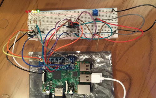
Figure 10-1. Example power meter connections
As you can see in the photo, I’m cheating a bit by using the Adafruit GPIO Reference Card for Raspberry Pi 2 or 3 ( www.adafruit.com/products/2263 ), which makes locating the SPI pins much easier than counting pin numbers.
The MCP3008 chip is in the center of the breadboard. You cannot see it in this photo, but chips have a small semicircular notch on one end. This indicates the side that contains pin 1 so that you can orient the chip correctly. In this case, you orient the chip on the breadboard with pins 1–8 on the far side of the breadboard (away from the Raspberry Pi as shown in the photo). This is because the SPI interface pins are located on the nearer side (pins 9–16). Orienting the pins closest to the Raspberry Pi makes the connections a bit easier. Figure 10-2 shows the pin layout of the MCP3008. Notice how the pins are numbered. Most are self-explanatory like the channel pins, but all are documented on the data sheet from Adafruit ( https://cdn-shop.adafruit.com/datasheets/MCP3008.pdf ).
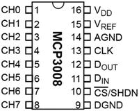
Figure 10-2. MCP3008 pinout
Figure 10-3 shows all the connections needed.
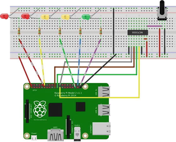
Figure 10-3. Connections for the power meter project
Notice how I arranged the LEDs. I placed the red LEDs to the left, the yellow in the middle, and the green to the right. More specifically, I plugged the negative leg of each LED into the GND rail on the breadboard. This allows me to make one connection from one of the ground pins on the GPIO to the breadboard rail, which I can then use to plug in the GND leg of the components. For example, each positive leg of each LED is plugged into the breadboard so that you can plug the corresponding resistor across the DIP trough and connect those to the appropriate GPIO pin. Also, I placed the MCP3008 in the center spanning the DIP trough. Make sure that you plug it in so that pins 1–8 are on one side of the breadboard and that pins 9–16 are on the other side.
If you are following along with this chapter working on the project, make the hardware connections now. Don’t power on the board yet; but do double- and triple-check the connections.
Write the Code
Now it’s time to write the code for our example. Since you are working with several new components, I introduce the code for each in turn. The code isn’t overly complicated, but may not be as clear as some of the code from previous projects. I’ve decided to use C#, but you could implement this project in C++. If you are a big C++ fan, I encourage you to do just that using the following as a pattern!
Note
Since you have learned all the basics of creating projects in Visual Studio, including how to build and deploy applications, I omit the details of the common operations for brevity.
The project uses a potentiometer. You read its value (via the ADC) and convert that to a scale that you can use to decide how many LEDs to turn on (and consequently those that need to be turned off). You also use a new technique for debugging the code. Thus, you need to start a new project, set up the SPI interface, write code to communicate with the ADC, and code to turn the LEDs on and off. You will use the DispatcherTimer class to periodically check the potentiometer and control the light sequence like you did in the last project.3 Let’s talk about the debugging feature first, and then we will walk through building the project.
Debug Output
Visual Studio supports an interesting and very powerful feature that permits you to insert print statements (and more!) in the code to help you debug your code. It is similar in some ways to the old school print statement trace (a log of statements written to a file), which are written as the code runs. However, in this case, the statements appear in the Output window of Visual Studio. To use the feature, add the following namespace to your code.
using System.Diagnostics; // add this for debuggingYou use the Debug class from this namespace to write out values so you can see them in the output window as you run the code in debug. The following code shows some examples of the methods you use to report data. Some are informational (the proverbial, “I’m here!”), while others show how you can print out the values of variables.
Debug.WriteLine("Sorry, the GPIO cannot be initialized. Drat.");Debug.Write("Val read = ");Debug.WriteLine(valRead);
Here I use two methods: Write(), which writes a string without a carriage return/line feed (CRLF) symbol (sometimes called a newline), and Writeline(), which writes the CRLF.
The output of this code is shown in the output window. The following shows an excerpt of the output from this project. It is to see the progress of the code. There is much more to this class, but this gives you a taste for what is possible with this alternative debugging technique.
...GPIO ready.Setting up GPIO pin 21.Setting up GPIO pin 20.Setting up GPIO pin 19.Setting up GPIO pin 18.Setting up GPIO pin 17.Setting up the MCP3008....
Tip
For more information about the system diagnostics debug class, see https://msdn.microsoft.com/en-us/library/system.diagnostics.debug%28v=vs.110%29.aspx .
You must compile your code in debug mode and run the debugger to see the output. If you compile in release mode, the debug code is ignored automatically and not included in the executable code (binary file).
New Project
You will use the same project template as the last project—the Blank App (Universal Windows) template. Use the name PowerMeter for the project name. You can save the project wherever you like or use the default location. Once the project opens, double-click the MainPage.xaml.cs file. This is where you put most of the code for the project. There are three namespaces you need to include. Go ahead and add those now, as shown next.
using Windows.Devices.Gpio; // add this for GPIO pinsusing System.Diagnostics; // add this for debuggingusing Windows.UI.Core; // DispatcherTimer
Tip
You may have noticed some of the namespaces are greyed out. This indicates the namespace may not be needed. If you right-click on one, you can remove any unnecessary namespaces.
Next, you need to add some variables and constants. You add constants for the number of LEDs and maximum potentiometer value (1023). You also add variables for the meter pin numbers and the GPIO pin variables. Finally, you add a variable for the timer.
// Power meter pins, variablesprivate const int numLEDs = 5;private const float maxPotVal = 1023;private int[] METER_PINS = { 21, 20, 19, 18, 17 };private GpioPin[] Meter = new GpioPin[numLEDs];// Add a Dispatch Timerprivate DispatcherTimer meterTimer;
Next, you’ll add a variable for the MCP3008 and instantiate an instance for the new class. In this case, you create a new class to encapsulate the code for the ADC. You’ll see this in a later section.
// Instantiate the new ADC Chip classADC_MCP3008 adc = new ADC_MCP3008();
Last, you’ll add a constant for the channel on the ADC that you will use. In this case, you use channel zero.
// Channel to read the potentiometerprivate const int POT_CHANNEL = 0;
The code in the MainPage() function initializes the components, the GPIO, and the new ADC class. You also set up the timer. In this case, you use a value of 500, which is one-half a second. If you adjust this lower, the solution is a bit more responsive. You can try this once you’ve got it to work and tested. Listing 10-1 shows the complete MainPage() method.
Listing 10-1. MainPage Method
public MainPage(){this.InitializeComponent();InitGPIO(); // Initialize GPIOadc.Initialize(); // Call initialize() method for ADC// Setup the timerthis.meterTimer = new DispatcherTimer();this.meterTimer.Interval = TimeSpan.FromMilliseconds(500);this.meterTimer.Tick += meterTimer_Tick;this.meterTimer.Start();}
Finally, you must add the reference to the Windows 10 IoT Extensions from the project property page. You do this by right clicking the References item on the project item in the Solution Explorer.
Initialize GPIO
As usual, you must provide the InitGPIO() method you called in the MainPage() method.4 Recall, you want to set up the GPIO controller and initialize the pins you are going to use. In this case, you must initialize the five LED pins and since you have them in an array, you can use a for loop to accomplish the task.
While you are at it, you’ll also use a few diagnostic statements to record whether the GPIO controller succeeds or not and the state of the pins. You can see these calls are made using the Debug.Write(), which does not write an end of line and Debug.Writeline(), which does write the end of line character. Listing 10-2 shows the completed InitGPIO() method.
Listing 10-2. Initialize GPIO Method
// Setup the GPIO initial statesprivate void InitGPIO(){var gpio = GpioController.GetDefault();// Show an error if there is no GPIO controllerif (gpio == null){Debug.WriteLine("Sorry, the GPIO cannot be initialized. Drat.");return;}Debug.WriteLine("GPIO ready.");// Initialize the GPIO pinsfor (int i = 0; i < numLEDs; i++){this.Meter[i] = gpio.OpenPin(METER_PINS[i]);this.Meter[i].SetDriveMode(GpioPinDriveMode.Output);this.Meter[i].Write(GpioPinValue.Low);Debug.Write("Setting up GPIO pin ");Debug.Write(METER_PINS[i]);Debug.WriteLine(".");}}
Controlling the LEDs
Next, you need code to control the LEDs. You’re using the timer class to fire an event every 500 milliseconds (one half of a second). In the MainPage() method, you assigned the name meterTimer_Tick() to the event. In this method, you must read the value from the potentiometer via the new ADC class (explanation is in the next section), and then calculate how many LEDs to turn on.
Since you are using five LEDs, you convert the value read from the potentiometer as a percentage, and then convert it to a scale from 0–5. You do this so you can use two loops: one to turn on those LEDs that should be on and another to turn the remainder off. Check the code to ensure that you understand how this works. You also see a copious amount of Debug.Write* methods to display the state of this method. Listing 10-3 shows the complete code for the meterTimer_Tick() method .
Listing 10-3. Controlling the LEDs
private void meterTimer_Tick(object sender, object e){float valRead = 0;int numLEDs_On = 0;Debug.WriteLine("Timer has fired the meterTimer_Tick() method.");// Read value from the ADCvalRead = adc.getValue(POT_CHANNEL);Debug.Write("Val read = ");Debug.WriteLine(valRead);float percentCalc = (valRead / maxPotVal) * (float)10.0;numLEDs_On = (int)percentCalc / 2;Debug.Write("Number of LEDs to turn on = ");Debug.WriteLine(numLEDs_On);// Adjust power meter LEDs On or Off based on value readfor (int i = 0; i < numLEDs_On; i++){this.Meter[i].Write(GpioPinValue.High);Debug.Write("Setting pin ");Debug.Write(METER_PINS[i]);Debug.WriteLine(" HIGH.");}for (int i = numLEDs_On; i < numLEDs; i++){this.Meter[i].Write(GpioPinValue.Low);Debug.Write("Setting pin ");Debug.Write(METER_PINS[i]);Debug.WriteLine(" LOW.");}}
Now that you’ve seen all the code for the main code file, let’s look at how the methods are placed in the class. Listing 10-4 shows the skeleton of the MainPage class. Use this as a guide to place the code in the right places. I omit the details of the methods for brevity.
Listing 10-4. MainPage Code Layout
...namespace PowerMeter{public sealed partial class MainPage : Page{...public MainPage(){...}// Setup the GPIO initial statesprivate void InitGPIO(){...}private void meterTimer_Tick(object sender, object e){...}}}
In the next section, you learn how to write the code to communicate with the ADC chip.
Code for the MCP3008
While you can write the code in this section in the project class MainPage, you’ll discover an example of making your code easier to maintain using a class module to group the code for the ADC. You’ve already seen a couple of references to this in the previous code, including the constructor (ADC_MCP3008 adc = new ADC_MCP3008();), initialization (adc.Initialize();), and reading a value on a channel (valRead = adc.getValue(POT_CHANNEL);). Thus, you will need these functions, at the minimum.
This class is pretty simple in scope but for larger classes and the objects they model, you want to create a design for the class. That is, you should consider everything the class needs to do to model the object or concept.
To add a new class, right-click the project and choose Add ä New Item.... Name the class ADC_MCP3008, as shown in Figure 10-4.
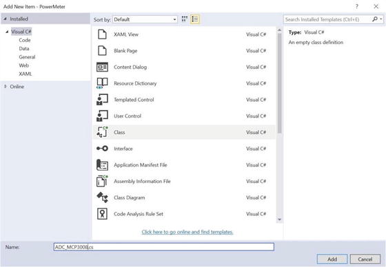
Figure 10-4. Adding a new class
When you create a class, you create a new file, as shown in Figure 10-4. Inside this new code file, you see a familiar skeleton. Of note is the same namespace as the main code and a list of namespaces that you will use. Open the file now and add the following namespaces. The need for each is shown in the comments.
using Windows.Devices.Spi; // add this for SPI communicationusing System.Diagnostics; // add this for debuggingusing Windows.Devices.Enumeration; // add this for DeviceInformation
Next, you need some variables and constants. You need a variable for the SPI device and constants for the MCP3008. In this case, you set constants for helping you read data as you shall see later in this section.
// SPI controller interfaceprivate SpiDevice mcp_var;const int SPI_CHIP_SELECT_LINE = 0;const byte MCP3008_SingleEnded = 0x08;const byte MCP3008_Differential = 0x00;
Next, you create the constructor method. You don’t need to do anything here so you’ll use a debug statement to indicate the class has been instantiated as follows .
public ADC_MCP3008(){Debug.WriteLine("New class instance of ADC_MCP3008 created.");}
Now that the preliminaries are set up, you can concentrate on the Initialize() and getValue() methods. The Initialize() method is used to set up the SPI interface for communicating with the ADC. I provide all the code that you need, but it is good to know what is going on. Listing 10-5 shows the Initialize() method .
Listing 10-5. Initializing the SPI Interface
// Setup the MCP3008 chippublic async void Initialize(){Debug.WriteLine("Setting up the MCP3008.");try{// Settings for the SPI busvar SPI_settings = new SpiConnectionSettings(SPI_CHIP_SELECT_LINE);SPI_settings.ClockFrequency = 3600000;SPI_settings.Mode = SpiMode.Mode0;// Get the list of devices on the SPI bus and get a device instancestring strDev = SpiDevice.GetDeviceSelector();var spidev = await DeviceInformation.FindAllAsync(strDev);// Create an SpiDevice with our bus controller and SPI settingsmcp_var = await SpiDevice.FromIdAsync(spidev[0].Id, SPI_settings);if (mcp_var == null){Debug.WriteLine("ERROR! SPI device {0} may be in used.", spidev[0].Id);return;}}catch (Exception e){Debug.WriteLine("EXEPTION CAUGHT: " + e.Message + " " + e.StackTrace);throw;}}
First, you set some variables of the SPI device class, including the line you will use (chip select = 0), the clock frequency (3.6 MHz) or 3.6 million times a second, and the mode (0), which is the default. Mode defines how the values are sampled.5 Next, you get the device name (string) and then call a system method named await() that spawns a thread to wait for the chip’s SPI interface to wake and set up. You do this because the SPI device is actually running on a separate thread.
You place all of this code in a try block in case the SPI bus fails (say if you misconnect one or more wires) using debug statements to track the progress and report success or failure. Don’t worry too much if this code seems very strange. I should note that this may not be the only way to set up an SPI communication, but it is compact and captures a failed initialization.
Now you’re ready to learn how to get data from the ADC. While the last method was a bit complex, reading a value is a bit more complex. Recall that you must write before you can read. In this case, you send an array of three bytes and you get back an array of three bytes, where the first byte sets the start bit, the second byte contains the command (shifted 4 bits to the left) and the channel select, and the third byte doesn’t matter.
How did I discover this information? I read the data sheet! While it takes a bit of patience because many data sheets are written in a style known as “by engineers for engineers,” which means that they can be a bit terse and not very easy to read. However, in this case you see a very good explanation of the data needed for reading and writing data. Figure 10-5 shows an excerpt from the data sheet.
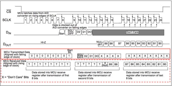
Figure 10-5. Communicating with the MCP_3008
I highlight the relevant portion for sending data to the chip in a solid box and the portion for receiving data in the dashed box. Here you see that the second byte for sending data holds the information for the single ended command and the command (0x8) shifted to the upper 4 bits (the order of bytes in memory is called endianness 6).
Notice the data you get back from the chip. Here you see you get 10 bits followed by a 0 (null) that are returned in the third and part of the second byte. Thus, you need to write code to capture the 10 bits in the second and third byte, and then mask out the bits starting with the null bit. Since the bits in the second byte are the higher bits, you need to mask out the bits that you don’t need, and then shift them so that you can interpret the two bytes as an integer (a common trick when working with byte streams). Listing 10-6 shows the completed getValue() method .
Tip
Although this may seem confusing, the number and order of the bits is defined by the manufacturer and not a general case. You should always read the data sheet for each device to learn how to implement its protocol. Fortunately, when you are able to use custom libraries (as you will see in later chapters), the protocol is implemented for you.
Listing 10-6. Reading Data from the ADC
// Communicate with the chip via the SPI bus. You must encode the command// as follows so that you can read the value returned (on byte boundaries).public int getValue(byte whichChannel){byte command = whichChannel;command |= MCP3008_SingleEnded;command <<= 4;byte[] commandBuf = new byte[] { 0x01, command, 0x00 };byte[] readBuf = new byte[] { 0x00, 0x00, 0x00 };mcp_var.TransferFullDuplex(commandBuf, readBuf);int sample = readBuf[2] + ((readBuf[1] & 0x03) << 8);int s2 = sample & 0x3FF;return sample;}
The first thing you may notice is the method takes the channel number as a parameter. This allows you to use the method to read other channels and indeed you do so in the next project.
Notice also how you perform the byte manipulations to set up the command, transmit it with the TransferFullDuplex() method , which returns three bytes to the read buffer. You then shift bytes and mask out the parts that you don’t need, and then shift the remaining bytes so that you can read the value as an integer.
Once again, don’t worry too much if this code seems overly complex. You can find out more about the chip from the data sheet at https://cdn-shop.adafruit.com/datasheets/MCP3008.pdf .
Now that you’ve seen the individual methods of this class, let’s see how they are placed in context in the class. Listing 10-7 shows the skeleton for the ADC_MCP3008 class. I omit the details of the methods for brevity.
Listing 10-7. ADC_MCP3008 Class Layout
...namespace PowerMeter{class ADC_MCP3008{...public ADC_MCP3008(){Debug.WriteLine("New class instance of ADC_MCP3008 created.");}public async void Initialize(){...}public int getValue(byte whichChannel){...}}}
Tip
If you’d like to explore all the capabilities of the MCP3008, see the data sheet at https://cdn-shop.adafruit.com/datasheets/MCP3008.pdf .
OK, the code is ready for compilation! Be sure to check the earlier listings to ensure that you have all the code in the right place. Once you have entered all the code, you should now attempt to compile the code. Correct any errors that you find until the code compiles without errors or warnings .
Deploy and Execute
Now it is time to deploy the application! Be sure to fix and compilation errors first. Like you have with other applications, you want to compile the application in debug first (but you can compile in release mode if you’d prefer) and you must turn on the debugger on the board. You do this with the device portal.
Power on your board, and then connect to the board and turn on the debugger. Next, open the project properties to target the device and run with the remote debugger. Recall from the last chapter, you must modify two settings: the Remote machine name and the Authentication Mode. Set the Remote machine name to the IP address of your device with the port specified by the remote debugger when you started it from the device portal. For example, my device gave me the port number 8116 so I use 10.0.1.89:8116. Set the Authentication Mode to None.
Now you can deploy your application. Go ahead and do that now. You can run the deployment from the Debug menu, and when you do, you see the debug statements in the output window. Listing 10-8 shows an excerpt of the data you should see. When you start the debugger, the output window automatically opens and displays the debug output. If it does not, you can open the window manually and select debug from the drop-down menu.
Listing 10-8. Example Debug (Output Window)
...New class instance of ADC_MCP3008 created....GPIO ready.Setting up GPIO pin 21.Setting up GPIO pin 20.Setting up GPIO pin 19.Setting up GPIO pin 18.Setting up GPIO pin 17.Setting up the MCP3008....Timer has fired the meterTimer_Tick() method.Val read = 327Number of LEDs to turn on = 1Setting pin 21 HIGH.Setting pin 20 LOW.Setting pin 19 LOW.Setting pin 18 LOW.Setting pin 17 LOW....Timer has fired the meterTimer_Tick() method.Val read = 570Number of LEDs to turn on = 2Setting pin 21 HIGH.Setting pin 20 HIGH.Setting pin 19 LOW.Setting pin 18 LOW.Setting pin 17 LOW.Timer has fired the meterTimer_Tick() method.Val read = 571
Of course, you can run the application by starting it on your device using the Apps pane. Use the small triangle or arrow next to the application name to start the application, the square icon to stop it, and the trash can icon to delete it.
If everything worked correctly, you should see the lights change when the potentiometer is turned. If the lights don’t change, be sure you have the potentiometer oriented correctly. Once it is working, try it out a few times to ensure that you see the lights sequence several times.
Summary
Learning how to build complex IoT projects requires learning how to use some components that may require a bit of effort to set up and use. You saw this with a very simple component—a potentiometer. In this case, since the Raspberry Pi does not have and ADC, you had to use the ADC to “bridge” the devices. Fortunately, you were able to use the potentiometer with the ADC using the SPI bus to control several LEDs as a power meter simulation.
You saw a number of new things in this chapter, including the ADC, how to connect and set up an SPI device, how to read a potentiometer, and finally, how to use the debug feature to write out statements to the output window. While the project itself is rather simplistic, the code clearly was not.
The next chapter continues our set of example IoT projects that you can use to learn more about building IoT solutions. You learn how to use another sensor to measure ambient light. Indeed, you will be making a cool, automatic night-light.
Footnotes
1 And here’s another one!
2 For more information about SPI, see https://en.wikipedia.org/wiki/Serial_Peripheral_Interface_Bus .
3 There are other ways to do this, but this uses a technique we’ve seen previously.
4 You don’t have to name it InitGPIO(), but that is the common theme. Actually, any reasonable name is fine; but if you are going to share your code, InitGPIO() is a good name.
5 For mode explanations, see http://www.byteparadigm.com/applications/introduction-to-i2c-and-spi-protocols/ .