
Some of the more interesting IoT solutions are those that implement actionable devices or features that allow you to control hardware remotely. This could be controlling a remote control toy (car, truck, drone, moving a camera (pan, tilt, zoom), opening or closing a gate, and so forth, or simply controlling lights or locks remotely.
That’s the real key and trick to the solution—making the solution available remotely. One of the best ways to do that is to write a web interface (web page) as the user interface. More specifically, you implement a web server that has one or more pages with controls that allow you to control the actionable devices, lights, locks, and so forth.
In this chapter, you will see one method for building IoT solutions that control hardware remotely using a web page. You have already discovered the tools and techniques for turning LEDs on/off, reading data from sensors, and implementing PWM-controlled devices.
Unlike previous projects, the code for this project is not overly complicated, but it is different from the techniques you’ve seen. That is, you will use HTML and Python to implement a simple web server to remotely control hardware. I’ve kept the hardware portion simple so that you can focus on the implementation. There is an optional part that requires some soldering and cutting or drilling to assemble making the hardware for this project a bit more complicated than previous projects. Regardless, you can take the concepts presented and make all manner of interesting solutions. Let’s get started.
Overview
If you work in a cube farm1 or have a similar office arrangement, you may enjoy this project. You’re going to implement an out of office sign that you can use to inform your coworkers whether you are in your office or not. To make it interesting, you will use a servo to raise or lower a flag for IN or OUT. You will combine that with a set of LEDs that you can use to indicate why you are out. More specifically, you will use the following states.
Available: You are available.
Do not disturb: You do not want to be interrupted.
Out to lunch: You are away from your desk on lunch break.
Be back later: You are away from your desk but expect to return.
Gone for the day: You are not returning to your desk until the next business day.
A servo operates with pulse-width modulation (PWM) .2 That is, the faster the pulses you send it, the more (further) it will rotate. Typically, you would choose specific patterns to move the servo to one of several positions. Servos are used in all manner of solutions from mechanical movements in toys, robots, remote control planes, cars, and even 3D printers. Basically, if you need a small motor to move a lever, rotate something, steer, or move something in a precision manner, you may want to use a servo.
The servo that you use in this project is a typical miniature servo that you can find at most online electronics stores, including Adafruit ( www.adafruit.com/products/169 ), SparkFun ( www.sparkfun.com/products/9065 ), and online auction sites. Figure 14-1 shows a typical micro hobby servo .

Figure 14-1. Micro servo (courtesy of Adafruit)
As you can see in the photo, servos typically come with a number of arms you can use to connect a thin wire or rod from the servo to another component that you want to move. Servos have a range of motion of 90 degrees. A special form of servo—called a continuous rotation servo—can rotate 360 degrees. For this project, the normal 90-degree range of motion is all that you need.
When you use a servo, you must discover the positions you want for the feature. For example, in this project, you simply want to raise a flag so you need to know only two positions: one for when the flag is down and one for when the flag is raised. To do this, you need to know how to use PWM in your projects. Fortunately, you have seen an example of how to do this. Recall that you saw how to use PWM in Chapter 11. However, you’re going to cheat a little and use a nifty new product from SparkFun called a servo trigger ( www.sparkfun.com/products/13118 ).
The servo trigger is a breakout board that has three small potentiometers that you can use to control the fully counterclockwise position (or “off”) and fully clockwise position (or “on”/triggered) as well as the speed at which the servo turns. This is perfect for this project because you only need the two positions. Furthermore, since the board is designed to use a simple trigger event, you can use a single GPIO pin to toggle the board. How cool is that? Figure 14-2 shows the servo trigger with the connections highlighted.
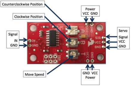
Figure 14-2. Servo Trigger from SparkFun
On the left is the signal connector with only two wires - a ground and signal. On the right is the connector for the servo. On the top and bottom are power connectors for the servo. This allows you to power the servo using 5V (most servos can operate on 3-9V). There are two connectors so that you can wire several servo triggers in series so you can use less wire for connecting power.
While the servo trigger makes using a servo for this project really easy, it does not come with any headers soldered. Thus, you will have to solder headers to the board. At a minimum, you need male headers on the signal, one of the power connections, and the servo connector. Soldering is not difficult but if you do not know how to solder, ask a friend to help you. If nothing else, you now have a really good reason to learn how to solder!
Note
The servo trigger is customized via the programming interface. See the product site on SparkFun for a complete guide (called the hookup guide).
Servos have three wires: one for the signal, one for ground, and another for power. These are normally colored brown, orange, and yellow respectfully. However, not all servos have the same colored wires. Table 14-1 shows some of the possible color schemes that vendors use (but there are many such variations. Just make sure that you don’t connect it backward! It is always best to check with your vendor on how to wire your servo.
Table 14-1. Servo Wires
Ground (pin 1) | Power (pin 2) | Signal (pin 3) |
|---|---|---|
Black | Red | White |
Black | Brown | Yellow |
Black | Brown | White |
Black | Red | Yellow |
Brown | Red | White |
Brown | Orange | Yellow |
Tip
To learn more about servos, see jameco.com/jameco/workshop/howitworks/how-servo-motors-work.html.
You will also use a number of LEDs to indicate a message for your coworkers. That is, when the LED is on, it indicates the current state. For example, if the flag is set to IN and the LED for “Do not disturb” is turned on, you are in the office but working on things that require your attention (such as a phone call or similar meeting) and do not want to be interrupted.
Finally, you will use HTML to write a small web page that you can use to control the hardware. To keep things as simple as possible, you will also use Python to write the code and use the Python web server library to implement a very basic web server. You will also keep the HTML code simple.
What you should gain from this project is how to write small applications to control hardware via a web page, how to use a servo (with help from SparkFun), and how to create specialized web-based solutions in Windows 10 IoT Core.
The really fun part of this project is building the sign itself. You have two options: (1) build the circuit on the breadboard, which allows you to explore all the basic concepts without the extra work, or (2) build the solution in an enclosure using a simple cardboard box that you can mount the LEDs, servo, and flag. You can hang this box on your cubical wall so that visitors can see your office status at a glance. However, this option does require a bit of soldering.
I present both options; thus, I recommend doing the first (on a breadboard) and then later build the solution in an enclosure. But first, let’s look at the hardware needed for this project.
Required Components
The following lists the components that you need. You can get the LEDs and servo from Adafruit ( www.adafruit.com ), SparkFun ( www.sparkfun.com ), or any electronics store that carries electronic components. The Servo Trigger board is available from SparkFun ( www.sparkfun.com/products/13118 ). Since this solution is a headless application, you need a monitor, a keyboard, and a mouse.
SparkFun Servo Trigger ( www.sparkfun.com/products/13118 )
Servo ( www.adafruit.com/products/169 ) or ( www.sparkfun.com/products/9065 )
(4) red LEDs
(1) green LED
(5) 150 ohm resistors
jumper wires: (10) male-to-female, (1) male-to-male
breadboard (full size recommended but half size is OK)
Raspberry Pi 2 or 3
power supply
Tip
The servo mount and flag are available in the source code download. They are 3D printer STL files that you can download and print or have printed for you using a 3D printing service.
Set up the Hardware
There are a number of connections needed for this project, and as usual, you will make a plan for how things should connect. To connect the components to the Raspberry Pi, you need five pins for the LEDs, one pin for the servo trigger, 5V power, ground, and four jumpers to complete the connections to the servo trigger breakout board. Table 14-2 shows the map I designed for this project.
Table 14-2. Connection Map for Out of Office Project
GPIO | Connection | Function | Notes |
|---|---|---|---|
5V (2) | Power for Servo Trigger | Power to breakout board | |
GND (6) | Ground for Servo Trigger, LEDs | GND on breakout board | |
20 | Servo Trigger Signal | Engage Servo | |
21 | Green LED | LED on | |
22 | Red LED #1 | LED on | |
23 | Red LED #2 | LED on | |
24 | Red LED #3 | LED on | |
25 | Red LED #4 | LED on |
Next, you need to make a number of connections on the breadboard for joining the ground rails together and connecting the servo trigger. Table 14-3shows the connections needed.
Table 14-3. Connections on the Breadboard
From | To | Notes |
|---|---|---|
Breadboard GND Rail#1 | Breadboard GND Rail#2 | |
Breadboard Power | Servo Trigger VCC | |
Breadboard GND | Servo GND (power in) | |
Breadboard GND | Servo GND (signal) | |
Servo | Servo Trigger servo header |
Figure 14-3 shows all the connections needed.

Figure 14-3. Connections for the Out of Office project
Here you see the breadboard implementation of the project. Recall from earlier discussions, this is how most projects start out—as a set of circuits implemented on a breadboard before being transferred to an enclosure, a printed circuit board designed, and so forth.
There are GPIO connections for each of the LEDs with the negative lead plugged into the breadboard for each LED. You also see a GPIO pin for the servo trigger as well as power connections for the servo trigger and ground for the LEDs. Lastly, you see the servo depicted connected to the servo trigger and an arm connected to the flag to raise and lower it on command.
If you are following along with this chapter working on the project, go ahead and make the hardware connections now. Don’t power on the board yet, but do double and triple check the connections.
Cool Gadget
SparkFun has a really neat adapter for working with the GPIO header on a Raspberry Pi with a breadboard. It’s called a Raspberry Pi Wedge ( www.sparkfun.com/products/13717 ). It comes with a 40-pin ribbon cable that you connect to your Raspberry Pi thereby allowing you to position the Raspberry Pi farther away from the breadboard or simply reposition the device without disturbing the breadboard circuits.
What I like most about it is it plugs into the breadboard along the DIP channel allowing you to connect more than one jumper to the pins, which is really helpful for connecting power or ground. The following is a photo of the Pi Wedge.
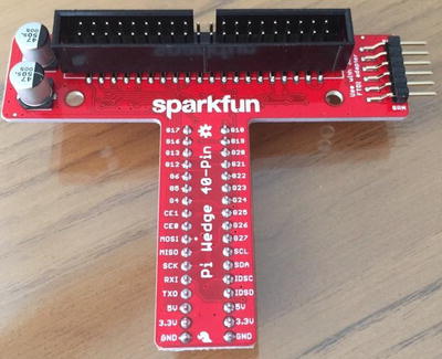
If you use this device, you can save yourself some time looking for the correct GPIO pin since they are clearly marked on the board (but they are not in the same order as the GPIO header on the board but, in my opinion, grouped together a bit more logically).
Write the Code
Now it is time to write the code for the project. Since it is written in Python, it is very easy to follow however the web server portion is not as intuitive as some of the previous projects. Let’s begin with creating the project and then walk through each of the parts that you need to implement.
New Project
Begin by opening a new project template. Choose Python ➤ Windows IoT Core in the tree and the Background Application (IoT) template in the list. This template creates a new solution with all the source files and resources you need for a UWP headed application. Figure 14-4 shows the project template that you need. Use the project name OutOfOfficefor the project name.

Figure 14-4. New Project dialog: Background Application (IoT)
The first thing you need to do is add a reference to the GPIO Python module. This is contained in the pywindevices.zip file from CPython UWP SDK. To add the reference, right-click the References in the Solution Explorer and choose Add Reference.... Once the dialog opens, click Browse and then navigate to the folder where you extracted the files. In that folder are subfolders for ARM or x86 builds. Choose the folder that matches your board (e.g., ARM for Raspberry Pi). Figure 14-5 shows the dialog that you can use to add the reference.

Figure 14-5. Adding the Python module references
Recall from Chapter 7, the module you want is named _wingpio. There are two versions of the reference: one for release builds (_wingpio.pyd), and one for debug builds (_wingpio_d.pyd). I recommend using the debug version until your application runs correctly. Once selected, you see all the available modules.
Now you can return to the code file and add the modules you want to use. You need two: the GPIO module and the http server module. You can add them as follows.
import http.server # Add for html webpage supportimport _wingpio as gpio # Add for GPIO
Next, you can write the code to create some variables that you need and initialize the GPIO module . The code to do this is as follows. There are a number of ways you could write these constants. I chose to use GPIO pins 20-25 and constants for each pin along with an array to make it easier to initialize the pins in a loop.
# Constants for GPIO pinsSERVO_PIN = 20AVAIL = 21DND = 22BBL = 23LUNCH = 24GFTD = 25LED_PINS = [AVAIL, DND, BBL, LUNCH, GFTD]
Next, you’ll add the HTML code for the web page.
Web Interface
To keep things as simple as possible, I decided to use a Python string to store the HTML code for the user interface. Further, I keep the code as simple as possible as not to detract from the goals of the project. That is, you want to learn how to interact with your IoT device via a web interface. I am certain those who know how to write HTML can improve the code, but it is fine to use as it is. Listing 14-1 shows the complete HTML code for the project.
Listing 14-1. HTML Code
## Create the HTML for the body of the page post (or get).# This is a parameterized string to make it easy to modify# without building the HTML code dynamically. Specifically,# the following are the parameters in the code.## 0 - "" or disabled to turn input "IN" on/off# 1 - "" or disabled to turn input "OUT" on/off# 2 - checked or "" to turn radio button Available on/off# 3 - checked or "" to turn radio button Do Not Disturb on/off# 4 - checked or "" to turn radio button Be Back Later on/off# 5 - checked or "" to turn radio button Out to lunch on/off# 6 - checked or "" to turn radio button Gone for the day on/off## Initial states are:# OUT = disabled# Available = checked#HTML = """<html><title>Windows 10 Hardware Control Example</title><body><form method=POST><br>Chuck's Office Status Board: <br><P><input type=submit Value='Set Status to IN ' name='in' {0}/><br><P><input type=submit Value='Set Status to OUT' name='out' {1}/><br><br><input type="radio" name="status" value="avail" {2}> Available<br><input type="radio" name="status" value="dnd" {3}>Do not disturb <br><input type="radio" name="status" value="bbl" {4}> Be back later<br><input type="radio" name="status" value="lunch" {5}> At lunch <br><input type="radio" name="status" value="gftd" {6}> Gone for the day <br></form></body></html>"""
There are a number of integers (0–6) surrounded by {}. These are placeholders for variables that you can complete with the format() function. You’ll see how to do that in the next section.
Also, the web page supports two input areas (like a button) that you use to choose whether you are in the office or out of the office. You also have a set of five radio buttons for choosing a status of your occupancy. Take a moment to read through the comments and code to understand the interface.
To make the code that updates the interface easier, I use an array of values to help populate the variables. In this case, you want to control which input areas are unavailable for clicking on (you use disabled to signal the state) and which radio button is checked (you use checked to turn it on). Thus, you create a variable called states, as follows. This is the default state for the input controls. More specifically, the IN input area is disabled and the available radio button is checked. Thus, the default starting state is IN and Available.
# List of states for the HTML code; each position is one of the controls.states = ["disabled", "", "checked", "", "", "", ""]
Again, if you feel you want to make the interface a bit better (or simply change the name), I encourage you to do so. Now, let’s look at the web server code.
Web Server Code
The web server code is a Python class derived from the http.server.BaseHTTPRequestHandler class named RequestHandler. There are several methods you need to implement: three required methods and one helper method. The following describes the purpose of each.
do_HEAD(): This method is used to return the headers and is called by the web server class itself. It is used to set the headers for the web page.
do_GET(): This method is called when the user connects to the web server to “get” the web page. Normally, this method is implemented to read an HTML file, such as index.html and send the contents to the client but for this project, you’ll use a string constant.
do_POST(): This method is called when the user submits input; in this case, when either of the input areas that you use as buttons.
_set_headers(): This is a private helper method to send the headers rather than duplicating the code in the preceding methods.
This sounds pretty simple and it really is a bare bones, lightweight web server . All you are going to implement is a simple sending of the preceding HTML code with the variables filled in. Let’s walk through what each of the preceding methods. Let’s begin with the basic layout of the class. The following shows the skeleton for the class.
# Implement a class for the request handlerclass RequestHandler(http.server.BaseHTTPRequestHandler):def _set_headers(self):...def do_GET(self):...def do_HEAD(self):...def do_POST(self):...
Note
I use a number of debug print() methods in the code. You can see this in the output window when interactively debugging the code.
The _set_headers() method sends the header back to the client. This is a standard mechanism and is coded as follows.
def _set_headers(self):# Prepare headersself.send_response(200)self.send_header('Content-type', 'text/html')self.end_headers()
The do_GET() method calls the _set_headers() method, and then prints a debug statement, and finally sends the HTML code to the client with the self.wfile.write() method. The following shows the code for this method.
def do_GET(self):# Prepare webpageself._set_headers()print("Setting states: {0}".format(",".join(states)))self.wfile.write(HTML.format(states[0], states[1], states[2], states[3],states[4], states[5], states[6]).encode())
Notice the HTML.format() call. Here you are formatting the HTML string populating it with the states values. The format() method replaces the variables in the string with the arguments passed (in order). In this case, you simply return the current status of the states.
The do_HEAD() method is simply a placeholder to call the _set_headers() method as follows.
def do_HEAD(self):# Send headerself._set_headers()
The do_POST() method is where all the work for the functionality takes place. I walk through this code a section at a time, followed by a complete listing to show the code in context. This method is called when the user submits the form. For example, when the input area is clicked. To determine what the user chose as input, you have to read and parse the data sent from the client.
To do this, you read the data sent to the server (the posted data) using the self.rfile.read() method . But first, you have to know how much data to read. You get this information from the self.headers.get() method passing content-length as the option. This returns the number of bytes in text (all data is in text) that you convert to an integer and use that to tell how many bytes to read. The following shows the code for this part of the method.
def do_POST(self):# Get response and repost resultscontent_len = int(self.headers.get('content-length', 0))post_body = self.rfile.read(content_len)option = None
Next, you reset the states array and all the GPIO pins to ensure that they are set correctly. This is not entirely necessary but helps when debugging the code to ensure that you know what the states are. It also helps to ensure that only the LED you want turned on is on at the end of the method. The following shows the code to accomplish these goals.
# reset states for safetyfor i in range(0,7):states[i] = ""# Turn all pins offfor i in LED_PINS:gpio.output(i, gpio.LOW)
Next, you check the data posted to see if the user clicked the IN or OUT input area. If it is the IN input area, the post data starts with “IN” and similarly, “OUT” if the OUT input area was clicked. We need to compare bytes not characters so you use the byte conversion shortcut.
If the IN input area was clicked, you trigger the servo to the LOW position, which rotates the servo to the default position. Note that it doesn’t matter which you choose for the default—LOW or HIGH—provided you orient the servo and flag (and label it) correctly to display IN for the default. If the OUT input area was clicked, you trigger the servo to the HIGH position, which rotates the server so that the flag displays OUT.
You also set the states for the input areas to toggle between the IN and OUT input areas by making one disabled. More specifically, if IN is clicked, the OUT input area is enabled and the IN input area is disabled. The reverse occurs when OUT is clicked. The following shows how you can accomplish these goals.
# Engage the servoprint("post body = {0}".format(post_body))if post_body.startswith(b"in"):gpio.output(SERVO_PIN, gpio.LOW)states[0] = "disabled"states[1] = ""# Turn on the LEDSelif post_body.startswith(b"out"):gpio.output(SERVO_PIN, gpio.HIGH)states[0] = ""states[1] = "disabled"
Notice the use of b before the strings. This is because the server class is expecting bytes rather than characters. Thus, you can convert a string to bytes using the shortcut b. You use these everywhere you work with strings in the method.
Next, you parse the body of the post to get which of LED switches (radio buttons) is checked. This information is passed in the post along with the name of the input area clicked. All you need to do is split the data return on the ampersand or “and” sign (&). Then, you can determine the option that was checked by splitting the second part (position 1) by the equal sign (=). This allows you to get the option (radio button) selected when the data was posted. Depending on which it is, you turn on that LED. The following shows the code needed.
# Need to parse to get the LED switchesparts = post_body.split(b"&", 1)if len(parts) > 1:option = parts[1].split(b'=')[1]self._set_headers()if option:if option == b"avail":states[2] = "checked"gpio.output(AVAIL, gpio.HIGH)elif option == b"dnd":states[3] = "checked"gpio.output(DND, gpio.HIGH)elif option == b"bbl":states[4] = "checked"gpio.output(BBL, gpio.HIGH)elif option == b"lunch":states[5] = "checked"gpio.output(LUNCH, gpio.HIGH)elif option == b"gftd":states[6] = "checked"gpio.output(GFTD, gpio.HIGH)
Notice that you once again use the byte conversion shortcut to compare the option (radio button selected). You also set the state for the radio buttons so that only the radio button that is checked is displayed. You do this because you are sending a new HTML stream to the client thus overriding the client state.
Finally, you call the self.wfile.write() method and format the HTML string with the variables as determined by the previous code.
print("Setting states: {0}".format(",".join(states)))self.wfile.write(HTML.format(states[0], states[1], states[2], states[3],states[4], states[5], states[6]).encode())
Listing 14-2 shows the completed web server code with all the methods placed in the class for reference (notice the indentation).
Listing 14-2. Completed Web Server Code
# Implement a class for the request handlerclass RequestHandler(http.server.BaseHTTPRequestHandler):def _set_headers(self):# Prepare headersself.send_response(200)self.send_header('Content-type', 'text/html')self.end_headers()def do_GET(self):# Prepare webpageself._set_headers()print("Setting states: {0}".format(",".join(states)))self.wfile.write(HTML.format(states[0], states[1], states[2],states[3], states[4], states[5],states[6]).encode())def do_HEAD(self):# Send headerself._set_headers()def do_POST(self):# Get response and repost resultscontent_len = int(self.headers.get('content-length', 0))post_body = self.rfile.read(content_len)option = None# reset states for safetyfor i in range(0,7):states[i] = ""# Turn all pins offfor i in LED_PINS:gpio.output(i, gpio.LOW)# Engage the servoprint("post body = {0}".format(post_body))if post_body.startswith(b"in"):gpio.output(SERVO_PIN, gpio.LOW)states[0] = "disabled"states[1] = ""# Turn on the LEDSelif post_body.startswith(b"out"):gpio.output(SERVO_PIN, gpio.HIGH)states[0] = ""states[1] = "disabled"# Need to parse to get the LED switchesparts = post_body.split(b"&", 1)if len(parts) > 1:option = parts[1].split(b'=')[1]self._set_headers()if option:if option == b"avail":states[2] = "checked"gpio.output(AVAIL, gpio.HIGH)elif option == b"dnd":states[3] = "checked"gpio.output(DND, gpio.HIGH)elif option == b"bbl":states[4] = "checked"gpio.output(BBL, gpio.HIGH)elif option == b"lunch":states[5] = "checked"gpio.output(LUNCH, gpio.HIGH)elif option == b"gftd":states[6] = "checked"gpio.output(GFTD, gpio.HIGH)print("Setting states: {0}".format(",".join(states)))self.wfile.write(HTML.format(states[0], states[1], states[2],states[3], states[4], states[5],states[6]).encode())
Wow! That’s a lot of code. Fortunately, the code isn’t too difficult but could use a bit of refactoring. That is, I kept the code simple and limited to the four methods described, but you could move the code to detect the input radio button and act on it to a separate method. But that is something you can do as an exercise .
Tip
In yet another effort to keep the code simple, there are no checks for validity of the radio button selections and the IN/OUT state. For example, it is possible to have the out to lunch button selected and the state IN. I leave this as an exercise for you to experiment with putting some practical limits on what can be selected. Hint: move the code for this to a new method to help keep the do_POST() method small.
Now, let’s discuss the code to initialize the GPIO pins and start the web server class.
Initializing the GPIO and Starting the Web Server
The last part of the code is used to initialize the GPIO pins and start the web server. For the GPIO pins, I use a loop to set up the pins and set the pins to LOW (off). Note that since the Available state is on at the start, you turn that GPIO HIGH (on).
Starting the web server requires making a call to http.server.HTTPServer() where you pass in the port you want to use (8081) and the name of our class (RequestHandler). This returns an instance to the HTTP server (you use the variable name httpd) and simply calls the httpd.serve_forever() method to start the web server and run indefinitely. Listing 14-3 shows the initialization and web server startup code.
Listing 14-3. Initialization and Web Server Startup Code
# Initialize the pins, set to LOW (OFF)for i in LED_PINS:gpio.setup(i, gpio.OUT, gpio.PUD_OFF, gpio.HIGH)gpio.output(i, gpio.LOW)gpio.setup(SERVO_PIN, gpio.OUT, gpio.PUD_OFF, gpio.HIGH)gpio.output(SERVO_PIN, gpio.LOW)# default is "Available"gpio.output(AVAIL, gpio.HIGH)# Run the http server indefinitelyhttpd = http.server.HTTPServer(("", 8081), RequestHandler)print('Started web server on port %d' % httpd.server_address[1])httpd.serve_forever()
Now let’s look at all of this code in context.
Completing the Code
So far, you’ve seen each part of the code separately. Listing 14-4 shows a code skeleton for reference to help you understand the order in which you put the code.
Listing 14-4. Complete Code for Out of Office Project
## Out of Office sign with mechanical IN/OUT sign## Windows 10 for the Internet of Things (Apress)## Dr. Charles Bell#import http.server # Add for html webpage supportimport _wingpio as gpio # Add for GPIO# Constants for GPIO pins...## Create the HTML for the body of the page post (or get).# This is a parameterized string to make it easy to modify# without building the HTML code dynamically. Specifically,# the following are the parameters in the code.#...HTML = """<html>...</html>"""# List of states for the HTML codestates = ["disabled", "", "checked", "", "", "", ""]# Implement a class for the request handlerclass RequestHandler(http.server.BaseHTTPRequestHandler):def _set_headers(self):...def do_GET(self):...def do_HEAD(self):...def do_POST(self):...# Initalize the pins, set to LOW (OFF)...# default is "Available"gpio.output(AVAIL, gpio.HIGH)# Run the http server indefinitely...
Caution
Compiling or building the code performs only the most basic of tests. It does not verify that the code is correct.
OK, now you're ready to deploy the application to your device. Go ahead, set everything up and power on your device .
Deploy and Execute
Once the Raspberry Pi has booted, you’re ready to deploy the application to your Raspberry Pi (or other device). Recall from Chapter 7, you have to set up the debug settings to specify the IP address of your Raspberry Pi. Fortunately, you only have to change two items as indicated in Figure 14-6. Remember to choose ARM for the platform. Click Apply and then OK to close the dialog.
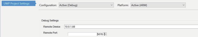
Figure 14-6. Debug Settings for deployment
Once these are set, you can deploy the application from the Build menu. Once the deployment is complete, you can start the application. We do this by visiting the Device Portal and selecting the application from the Apps panel. Figure 14-7 shows an excerpt from this page.
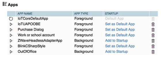
Figure 14-7. Device Portal apps page: Starting the app
Since this is a headless application, you must add it as a startup application in order to execute. To do so, click the Add to Startup link. This launches the application and in a moment you should see the triangle icon turn into a small square (toggles from start to stop) and the link changes to Remove from Startup. You cannot start the application with the triangle icon because this is a startup project. If you try to do this, you get a message that the application failed to start. Be sure to click the link instead. To stop the application, click the Remove from Startup link. Figure 14-8 shows how the link changes once the application starts.

Figure 14-8. Device Portal apps page: stopping the app
Once the application has started, you can now connect to the device via the web server port 8081 using the following link. Be sure to substitute the IP address of your device.
10.0.1.89:8081Once you connect, you should see the web page as shown in Figure 14-9. This is the default settings for the first run of the page and is generated from the preceding do_GET() method.
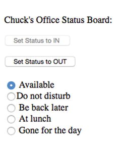
Figure 14-9. Web interface: default state
Now, play around with the input areas and radio buttons for a bit. You should see the servo trigger from one position to another as you change the IN/OUT state. Similarly, the LEDs should illuminate corresponding with the radio buttons you chose. Figure 14-10 shows one such state you could toggle.
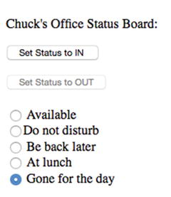
Figure 14-10. Web interface : out of office status
You should see the servo turn to one position when the IN input is clicked and another when the OUT input is clicked (and back again). This may not seem very interesting since you want to use the servo to raise and lower a flag, but you can use your imagination at least and see the wonder of remotely controlling mechanical devices. In fact, I show you how to prototype an enclosure complete with the mechanical flag apparatus in the next section.
Tip
You do not have to complete the enclosure task. I provide it as a mild diversion to show what is possible. As you will see, it requires a bit of mechanical aptitude (must be able to use a hobby knife, scissors, etc.) as well as a bit of patience to get it going. If nothing else, it may be an interesting read that sparks your own ideas.
If you got this to work, congratulations! You have now been introduced to a whole new venue of IoT applications—making things move. If this interests you, I encourage you to look for more helpers and aides, such as the Servo Trigger board from SparkFun. There are an awful lot of cool projects you can imagine with just a servo or a dozen. But making things move in your IoT projects isn’t limited to servos. There are stepper motors, continuous rotation motors, actuators and much more that you can explore.
If you are having trouble getting this project to run or deploy, be sure to revisit Chapter 4 and Chapter 7 for tips. If the application starts but doesn’t respond correctly, double-check your code to ensure that it is the same as listed in this chapter. Remember, you can always run the interactive debugger and step through the code. If you decide to do this, I recommend placing breakpoints in each of the do_GET() and do_POST() methods so you can trace them to diagnose errors.
Now let’s go over how to get started embellishing this project by prototyping an enclosure.
Prototyping the Out of Office Sign Enclosure
The following is a brief detour from your discovery of Windows 10 for the IoT. In this section, I present one possible way to take the preceding project and make it into something you could use every day. That is, one thing that separates an experiment from a practical application is how it is packaged.
You could leave your components plugged into a breadboard and use it, but some projects like the one in this chapter aren’t very practical. In this case, it is because you have a mechanical element—the IN/OUT flag. Wouldn’t it be nice to see this in an enclosure so you can see the flag move?
You may be wondering how to get started. Or perhaps you have doubts about how to build such a thing. Read on to see one approach to discovering how to build a permanent enclosure. You’re going to use a technique called prototyping, where you build a solution with the intent to experiment on how best to solve the problem.
Most prototypes therefore are called throwaway prototypesbecause they often are of lower quality and makeshift at best. Moreover, they often have little or no aesthetic value. Finally, prototypes are often used to prove a concept. That is what you will do in this section. The goal is to see how to design an enclosure but you also build it so that you can dismantle it either to build a permanent solution or to recover the components for use in other projects.
As you can imagine, this task requires a bit of work and of course you need to power down your device and partially disassemble the project. You can leave the breadboard connections to the Raspberry Pi because you reuse those, but all others can be disconnected.
I try to keep it relatively easy by using a cardboard box and as few tools and additional components as possible. That said, the following lists some additional parts you need if you want to follow along with this exercise .
Small cardboard box with or without lid
Double-sided tape (e.g., 3M mirror mounting tape)
Assorted M3 screws and nuts (or equivalent)
Mini breadboard (optional, but helpful)
Additional male/female jumper wires
Small solder prototyping board (called a protoboard)
Soldering iron and solder
6 to 8 inches of small gauge wire to connect servo to the flag
3D printed parts from the source download
OK, so that’s a lot more than a few items. And, yes, you are going to be soldering a bit. You could skip this part, but you need some way to attach wires to the LED legs and resistors to the LEDs. As you will see, the board that you will build isn’t complicated. If you do not know how to solder, ask a friend to help you—now is a great time to learn!3
The 3D printed parts are pretty simple and can be found in the source code archive for the book from the Apress web site. The parts are shown in Figure 14-11 and include an example flag and a mount for the servo.
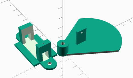
Figure 14-11. 3D Printed parts for enclosure
If you do not have a 3D printer or don’t know anyone who does, you can visit a number of online 3D printing services, which you can upload design and (for a fee) they will print and ship them to you. I like shapeways.com as they have an excellent reputation and offer a variety of materials and finishes. However, you could also checkout freelance 3D printing services, such as 3D Hubs ( www.3dhubs.com ), which allows you to search in your area for someone willing to print parts for you—sometimes at a much reduced price or even for only the price of the weight of filament (plastic) used. Enthusiasts are cool like that.
The nice thing about these parts is you can either bolt them to the enclosure or in the case of the servo mount, glue them to the enclosure (if you don’t want to see bolts through the face of the enclosure).
Of course, you could invent your own parts for mounting the servo and creating a flag. For example, you could use double-sided tape or glue to attach the servo to the box. For the flag, you could cutout another piece of cardboard or other material. The good news is this is a prototype and you are free to experiment at will with whatever ideas or materials you have at hand.
Now, let’s see how to assemble a circuit board for mounting the LEDs and resistors.
Assembling the Circuit Board
I chose to use a soldered prototyping board (called a protoboard for short) to mount the LEDs to make it easier to mount them in the enclosure . As I mentioned, you could simply solder the resistors to the LEDs and then solder a wire to them eliminating the need for a breadboard or circuit board, but having them on the board makes it easier to transfer the components from the prototype to a permanent enclosure.
In fact, you are going to use the solder protoboard to mount the LEDs and resistors just like you did on the breadboard. More specifically, you are going to solder all the ground legs together and each positive leg to its own resistor. You then use the legs of the resistor and one of the legs from the LEDs as mounting pins for your female jumper wires. Don’t worry. It’s not as crazy or difficult as it sounds.
Begin by placing the LEDs on the protoboard so that the legs are in separate solder pads. Take a look at the protoboard closely. You want to use the solder pads to hold the LED, but you need to make sure that you don’t solder the legs to together. Go ahead and solder them in place. Figure 14-12 shows how the LEDs should look when soldered in place.
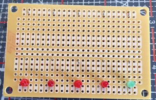
Figure 14-12. LEDs soldered to protoboard
I placed the green LED on the right side. I plan to use this as the “Available” indicator. It doesn’t really matter which color you choose and it could be a bit easier to use the same color. That is, using a different color means having to orient the board a certain way. Just be sure to imagine the LEDs positioned on the reverse side so you can place them in the correct order if you are using different colors.
Next, place the resistor on the opposite side of the protoboard bending the LED leg so that it touches on side of the resistor. Take the other side and push it through and back out the backside of the protoboard. Now solder the LED leg to the resistor and the other side of the resistor to the protoboard solder pad.
While you are soldering on the reverse side of the protoboard, go ahead and bend the GND pins of the LEDs toward one edge (the long edge). This allows you to solder them all together saving the last one as a mounting point. This is easier to visualize in a photo. Figure 14-13 shows the completed reverse side of the protoboard.

Figure 14-13. Completed protoboard (LED circuit board)
Notice how I use the extra leg from the resistors as mounting points. Here I just bent them 90 degrees to the board. They were a bit long so I cut them off but be sure to leave at least 12-15 mm so you can fit the jumper wires. Look closely and you will see on the left side how I joined the GND legs of the LEDs together, terminating with one leg of the last LED used for mounting the jumper wire from the Raspberry Pi.
I have two 3-pin headers on the bottom edge of the board. I placed these here so that I can connect one VCC and one GND from the Raspberry Pi but I decided to not use these. You can safely ignore them.
Now that you have the LED circuit board, the mount for the servo, and flag, let’s now see how to modify the cardboard box to house these components. In other words, here’s where the prototype effort pays the bills.
Making the Enclosure
Let’s begin by mounting the servo onto the servo mount. You can use two M1.5 screws or similar to mount the servo. The fit will be tight, but you can thread the wire leads through the opening in the side of the mount before you bolt it down. If the box has an attached lid or cover, you may want to cut it off to make it easier to work with.
Next, take a section of thin wire, such as the type used in auto and motorcycle racing. The wire I use is called safety wire, which is used to secure nuts and bolts from coming loose or worse falling out.4 A length of about 6 to 8 inches should be enough. This wire is often called a cable or a rod when used with a servo. The small plastic piece that mounts to the servo is called the servo arm. Choose the longest of the arms and place it on the servo. Don’t secure it yet. You need to make some modifications first. Take the wire and end it so that one end forms a vertical area that the servo can use to push and pull. The other end can be bent in a U shape for the same purpose when mounted to the flag. Finally, you need to put another bend in the center so that the arm can align with the flag (the servo is taller than the flag mount). Figure 14-4 shows an illustration of how the arm should be shaped.
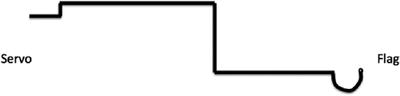
Figure 14-14. Forming the servo rod/cable
Next, you need to place the servo and flag on the inside of the box. Be sure to orient the flag so that it is about 40mm above the servo. Go ahead and attach the rod to the servo and the flag. You may need to drill out the servo arm and the flag mount a bit depending on the thickness of the wire. Looser is better.
Without the servo connected and powered on, try moving the arm in a 90-degree arc to see where to place the flag. The placement will depend on the size of the box you are using and the length of the rod. For my box, a 6-inch rod (before bending) was a perfect fit. I aligned the center of the servo with the pivot mount for the flag. Take some time to experiment with this until you’re convinced it will work. That’s part of the fun—seeing where to place things.
Once you have the general placement of the servo and flag, you can start marking and cutting the box.
Marking the Box for Holes
Let’s start with the LED circuit board. For this, you can place five 2.5mm holes spaced 13mm apart on the right side of the box. Press or drill out these holes, and then mount the LED circuit board with double-sided tape to the inside of the box.
Next, place the servo and flag inside the box and once again rotate the servo to ensure that there are no collisions. Once you figure out where to place the servo, mount it with double-sided tape or drill holes, and use bolts to mount the servo.
Next, place the flag in the box and mark where the hole for the bolt should be. Don’t mount the flag yet, just drill the hole for it, and then mark a box approximately 22mm wide by 17mm high next to it. This is the window in which the IN or OUT values will show. Figure 14-15 shows the box with holes for the LEDs, flag, and flag mount.
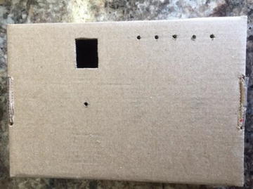
Figure 14-15. Box with holes drilled
Before you mount the flag, place a piece of white paper over the flag, cut it to fit with some overlap, and then tape the ears down, as shown in Figure 14-16. This allows you to write on the flag from outside the box. Go ahead and mount the flag in the box with a long M3 bolt and nut or similar.
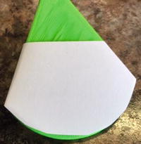
Figure 14-16. Masking the flag
Now you can put the rest of the components in the box.
Putting it all Together
Use double-sided tape to mount the Servo Trigger in the box away from the flag. Also, mount the mini breadboard inside the box to the right of the servo. Most mini breadboards come with double-sided tape. Now you can wire everything together. Use the mini breadboard to route the 5 LED wires, GND wires for the Servo Trigger and LEDs (you use the same row on the breadboard). Connect the servo to the Servo Trigger and finally GND and 5V power from the Servo Trigger to the breadboard. Figure 14-17 shows the completed wiring inside the box .
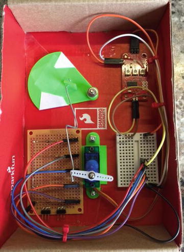
Figure 14-17. Components mounted
Be sure the Servo Trigger is unobstructed or at least positioned so that you can get to the three potentiometers on the board to tune it.
Caution
Never rotate a servo when it is powered on. Also, never connect or disconnect a servo when the circuit is powered on.
Now you can connect your enclosure to the Raspberry Pi via the original breadboard. Once again, you wire the 5 LEDs, Servo Trigger, GND, and 5V power from the Raspberry Pi breadboard to the mini breadboard in the enclosure. Figure 14-18 shows the completed enclosure minus the Raspberry Pi .
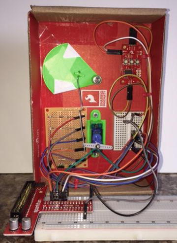
Figure 14-18. Raspberry Pi connected
I used a couple of zip ties to keep the unruly wires under control. Take a moment to examine the photo for ideas on where to place components in your box. Be sure there are no collisions in the movement of the servo and flag.
Caution
Be sure to double-check and triple-check your wiring before powering on your device. There are a lot of wires in there and it is very easy to get things mixed up. Use the tables earlier in the chapter as a guide to trace each and every wire from the Raspberry Pi GPIO pin to the device. For example, ensure that GPIO 20 is connected to the Servo Trigger signal pin.
There’s just one more step to perform. You need to tune the servo so that the flag moves correctly and it is shown in the window.
Tuning the Servo Trigger
The Servo Trigger has three small potentiometers on the board for adjusting the servo. Use these to change the off and on (triggered) positions of the servo so that your flag clearly shows in the cutout window and that it travels far enough to change from one value to another (from IN to OUT).
Use a small flat blade screwdriver to adjust the potentiometers. The A potentiometer adjusts the off position and the B potentiometer adjusts the on (triggered) position. If you find this to be the opposite, you can either roll with it that way or simply rotate the entire servo mount 180 degrees.
You may find that you have to experiment a bit to get this right. This is really the hardest part of the prototype and the reason you’re using a temporary housing. You may have to adjust the wire that connects the servo arm to the flag shortening or bending it so that the action runs smooth. You may also have to detach and realign the servo arm to get it in the correct location.
Once you get the servo tuned correctly, take a moment to draw a small outline of the cutout on the flag in each position. You can then disassemble the flag and write IN and OUT in those locations.
OK, now you have your components assembled and the servo tuned. Let’s test it out!
Testing the Prototype
OK, so now the real fun begins. Before you power on the device, if you haven’t already done so, turn the box over and write the IN/OUT values on the flag and label the LEDs. I added my own comments here and there. Yes, my handwriting is terrible,5 but since it’s a prototype, all that matters is that it is legible.
Now, fire up the device and start the application. Your prototype should look very similar to the one in Figure 14-19.

Figure 14-19. Chuck is in his office!
If you’re thinking it looks a little crude and very handmade, that’s OK. It’s a prototype and by definition (or practice), you don’t worry about aesthetics. Rather, once it works, you can then decide to implement it using a different medium with nicer materials, better handwriting (or better still printed labels), and more.
Now, try out your application and watch your sign change according to your commands. Isn’t that cool? The sound of the servo cycling is a really powerful satisfying aspect of this prototype. Figure 14-20 shows the end state of my prototype for the day. I’m out of here!

Figure 14-20. Chuck has left the building...
Now that everything is working, I am sad to say the coolness and jubilation eventually wears off. Sure, you can impress your office mates with your prototype, but it eventually starts to look like a fifth grader made it. But remember, you built this as an exercise with the expectation you would either use it to design and build a better enclosure or simply dismantle the components for later reuse. Either way, bask in the delight of becoming a Maker and show it to all of your friends!
Taking it a Step Further
I chose to use a cardboard box for the enclosure for the project because it is easy to modify with a small hobby knife, you can write on it with a marker, and doesn’t detract from the lessons learned in writing the code. However, you may want to consider implementing this project using a more robust enclosure.6 Moreover, you could use an enclosure large enough to house your Raspberry Pi, too.
For example, you could purchase a plastic or aluminum enclosure and cut or drill the holes for the LEDS and flag mount. If you have access to a 3D printer, you could not only print the mounts and flag, as described earlier, or you can even design and print your own bezel. Another possibility is using a small piece of thin plywood to make the bezel and mount it in a deep photo frame or shadow box.
If you like this project and had as much fun as I did building it or better still if you want to take it to work and put it in service, I encourage you to consider taking the project a step further with a better enclosure. See Chapter 17 for ideas on where to publish your work. Be sure to reference this book as the origins of your idea.
Summary
I find those IoT projects (or any project) with mechanical elements really fun to design and implement. Mechanical movements allow you to bring a bit of whimsy and wonder to your projects. My interest in mechanical movements began as a child when I saw the early animatronics displays at Disney World and other amusement parks. Now that you have had a small taste of one method you can use to create such devices, you can begin to think about how to incorporate similar mechanisms in your projects.
In this chapter, you discovered how to build a nifty out of office sign with a mechanical flag and LEDs controlled from a web page. This represents the fundamental building blocks for other remote controlled IoT projects.
In the next chapter, you explore an exciting new venue for Windows 10 IoT development—the use of the widely popular Arduino microcontroller boards. Yes, that’s right. You can even make use of the Arduino with Windows 10! How cool is that?
Footnotes
3 Depending on the temperament of your friend, it could be a good time to watch someone solder. Be sure to take notes and pay attention so you can learn on your own.
5 Thereby supporting the assumption that academics and medical doctors, however successful, have all failed basic handwriting and penmanship in elementary school. Guilty.
6 Or at least one that looks better!