
The projects that you’ve encountered thus far have used GPIO pins to turn LEDs on or off. But what if you wanted to control the brightness of an LED? Given that you can only turn pins on (high: 3.3V) or off (low: 0V), you have no way to send less power to the LED. Recall the lower the power, the dimmer the LED. If you consider solutions (or features) of devices that are sensitive to ambient light—such as a backlight keyboard—you may have noticed it changes brightness as the room becomes darker. In this project, you’re going to explore how such a feature works. That is, you’re going to build a fancy LED night-light.
Unlike the last project, this project is a bit more complex in concept. You must measure the ambient light in the room, and then calculate how much power to send to the LED using a technique called pulse-width modulation(PWM). You will also use the same analog to digital converter (ADC) and SPI interface from the last project, but you will implement it in a slightly different way. Let’s get started.
Note
Although this project is written in C#, other than the syntax and mechanics of building, the concepts of using a class are the same in C++.
Overview
You will design and implement an LED night-light using a light-dependent resistor (LDR, also called a photocell or photoresistor)1 read from an ADC (the LRD is an analog component like a potentiometer). The LDR is a special resistor that changes resistance depending on the intensity of ambient light.
You need to use the ADC because you want to read analog values and the Raspberry Pi (and many other boards) does not have analog-to-digital logic. That is, the GPIO pins are digital only. The ADC acts like a “bridge” between digital and analog devices. You will use the MCP3008 that you used in the last chapter .
The real trick to this solution is you must use a special library (namespace) in order to access the pulse-width modulation features of your Raspberry Pi. The library you will use is a contributed library and not part of the standard Visual Studio built-in libraries for Windows 10 IoT Core. However, the library isn’t difficult to install and you will reuse the class you built in the last chapter as the basis for implementing a class for controlling an LED (fading), as well as the ADC. The library is named the Microsoft IoT Lightning Provider (also called the Lightning software development kit or SDK).
Note
In order to use the Lightning SDK, you need Windows 10 IoT Core Version 10.0.10586.0 or later.
Since the LDR responds to light and the ambient light can vary, you will also use a simple user interface to allow you to adjust the sensitivity of the light sensor by restricting its range. That is, you will be able to set the minimum and maximum values for the range. Thus, you will be able to tune the solution to fit the ambient light levels.
Let’s look at the components that you need, and then see how to wire everything together.
Required Components
The following lists the components that you need. You can find these components in either of the kits mentioned in Chapter 9 or you can purchase the components separately from Adafruit ( www.adafruit.com ), SparkFun ( www.sparkfun.com ), or any electronics store that carries electronic components. Since this solution is a headed application, you will also need a monitor, a keyboard, and a mouse. If you want to run this application headless, you can but I recommend experimenting with the user interface to help tune the values that you need to make the fade effect work properly.
(1) LED (any color)
(1) 10K ohm resistor
(1) 150 ohm resistors (or appropriate for your LEDs)
(1) light-dependent resistor (photocell)
MCP3008 ADC chip
Jumper wires: (5) male-to-male, (8) male-to-female
Breadboard (full size recommended but half size is OK)
Raspberry Pi 2 or 3
Power supply
Monitor
Keyboard and mouse
Set up the Hardware
Once again, in order to help get everything connected correctly, you will make a plan for how things should connect. To connect the components to the Raspberry Pi, you need four pins for the ADC, one for the LED, one for the LDR, and one each for power and ground. You will also need to make a number of connections on the breadboard to configure the ADC chip and connect the LDR to the ADS. Table 11-1 shows the map I designed for this project. I list the physical pin numbers in parenthesis for the named pins. You will use male/female jumper wires to make these connections.
Table 11-1. Connection Map for Power Meter Project
GPIO | Connection | Function | Notes |
|---|---|---|---|
3.3V (1) | Breadboard power rail | Power | |
5V (2) | 10K resistor | Power to LDR | |
GND (6) | Breadboard ground rail | GND | |
MOSI (19) | SPI | MCP3008 pin 4 | |
MISO (21) | SPI | MCP3008 pin 4 | |
SCLK (23) | SPI | MCP3008 pin 3 | |
CC0 (24) | SPI | MCP3008 pin 5 | |
27 | LED | Resistor for LED |
Next, you need to make a number of connections on the breadboard. For these, you will use male-to-male jumpers. Table 11-2 shows the connections needed on the breadboard.
Table 11-2. Connections on the Breadboard
From | To | Notes |
|---|---|---|
Breadboard GND | LDR | |
Breadboard power | ADC VDD (pin 16) | |
Breadboard power | ADC VREF (pin 15) | |
Breadboard GND | ADC AGND (pin 14) | |
Breadboard GND | ADC GND (pin 9) |
Tip
See Chapter 9 for details on how to determine the correct resistor for your LED.
Once again, I am cheating a bit by using the Adafruit GPIO Reference Card for Raspberry Pi 2 or 3 ( www.adafruit.com/products/2263 ), which makes locating GPIO pins much easier than counting pin numbers.
Figure 11-1 shows all the connections needed. Take a close look at this drawing, because some connections may not be obvious (e.g., sending 5V power to the LDR).

Figure 11-1. Connections for the night-light project
Notice how the LDR and 10k resistor are configured. This is not a mistake. You want the resistor to connect to the second leg of the LDR and the LDR connecting to the channel 0 pin of the ADC as a pullup resistor. Also note how power to the LDR comes from the 5V pin (2) on the GPIO. The SPI connections are the same as the last project.
What is Pulse-Width Modulation?
IoT devices such as the Raspberry Pi can switch between exactly two voltages on their GPIO pins (0.0V or 3.3V). The problem is that many components can operate on a range of voltage. For example, a fan can rotate at different speeds based on the current fed to it. The higher the current, the faster the fan spins. The same is true for other components, such as LEDs, servos, and motors.
It is possible to simulate sending different current levels to a component using a technique called pulse-width modulation (PWM) . The process works by rapidly switching a pin (line) on and off at different frequencies (hence the pulse) for a given very short period of time (hence the width). The end effect is the device appears to be operating at lower voltages. For example, if you want only 3.0V from 3.3V, you must set the pin to operate at 90% or the pin will be on (through pulsing) at most 90% of the time.
This may sound a little strange and you may expect to see an LED fed by PWM flicker. The fact is, it is flickering, but it is doing so very quickly—too fast for humans to detect. In fact, many of the lights in your home or office cycle in a similar manner. The following diagram (see https://en.wikipedia.org/wiki/Pulse-width_modulation )2 is an illustration of how PWM generates current.
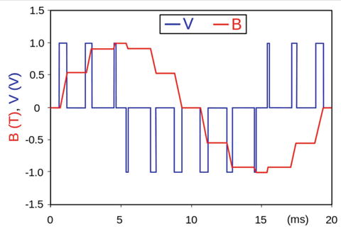
This shows a voltage source (V) modulated as a series of pulses creating a sine-like wave. The result is a sine-like current in the inductor (B). The current waveform is the integral of the voltage waveform. While this sounds all scientific/mathematical, just remember PWM is a technique for simulating different current values by turning the pin on and off rapidly in a specific pattern.
If you are following along with this chapter working on the project, go ahead and make the hardware connections now. Don’t power on the board yet, but do double- and triple-check the connections.
Write the Code
Now it’s time to write the code for our example. Since you are working with several new concepts as well as a new component, I will introduce the code for each in turn. I’ve decided to use C#, but you could implement this project in C++.
Note
Since you have learned all the basics of creating projects in Visual Studio, including how to build and deploy applications, I omit the details of the common operations for brevity.
The project uses an LDR to measure ambient light read via an ADC (MCP3008), the value read is used to control the percentage of current sent to an LED via PWM. Unfortunately, while the IoT devices you have for Windows 10 IoT Core have PWM support, Windows 10 IoT Core has only rudimentary support for PWM. Fortunately, there is an add-on library called the Microsoft IoT Lightning Providers that get you what you need to create a PWM output on a GPIO pin .
I like to use modularization to help make the code easier to write and maintain. It also helps to focus your efforts by concentrating on a specific concept to model. You will see this as you walk through the code. You will create a class for the ADC and a class for the PWM control of the LED. Finally, you use the DispatcherTimer class to periodically check the LDR and set the PWM percentage for the LED.3
Let’s talk about starting a new project and adding the resources that you need first (e.g., the Microsoft IoT Lightning Providers), and then we will walk through the entire code.
New Project
You will use the same project template as the last project—the Blank App (Universal Windows) template. Use the name NightLight for the project name. You can save the project wherever you like or use the default location. Once the project opens, double-click the MainPage.xaml.cs file. There are two namespaces you need to include. Go ahead and add those now, as shown next.
using System.Diagnostics; // add this for debuggingusing Microsoft.IoT.Lightning.Providers; // add for Lightning inteface
Next, you need to add some variables and constants. First, you create a constant for the GPIO pin for the LED (27) and an instance of one of the new classes that you create named LED_Fade. You see this class in a later section.
// Constants and variables for pinprivate const int LED_PIN = 27;private LED_Fade fader = new LED_Fade(LED_PIN);
Next, you create an instance for the timer.
// Timer to refresh the LED brightnessprivate DispatcherTimer refreshTimer;
Next, you add an instance of the ADC class, which you name MCP3008 to distinguish it from the class you created in the last project. You will see this described in a later section.
// Add the new ADC Chip classprivate MCP3008 adc = new MCP3008();
Finally, you need some variables and a constant for the LDR. You use these variables in conjunction with the user interface to adjust the lower and upper bounds for the light sensitivity. This is really nice because it allows you to experiment with the project while it runs rather than using constants or variables that you must modify, compile, and then rerun to test.
// Channel to read the photocell with initial min/max settingsprivate const int LDR_CHANNEL = 0;private int max_LDR = 300; // Tune this to match lightingprivate int min_LDR = 100; // Tune this to match lighting
The code in the MainPage() function initializes the components, the new LED fade class (fader), and the new MCP3008 class (adc). Each of these classes has an Initialize() method. There is also a method to initialize the lightning providers that must be called first. You will see this method in the next section.
You also set up the timer. In this case, you use a value of 500, which is one-half a second. If you adjust this lower, the solution will be a bit more responsive. You can try this once you’ve got it to work and tested. Listing 11-1 shows the complete MainPage() method .
Listing 11-1. MainPage Method
public MainPage(){InitializeComponent(); // init UIInitLightningProvider(); // setup lightning providerfader.Initialize(); // setup PWMadc.Initialize(); // setup ADC// Add code to setup timerrefreshTimer = new DispatcherTimer();refreshTimer.Interval = TimeSpan.FromMilliseconds(500);refreshTimer.Tick += refreshTimer_Tick;refreshTimer.Start();}
You need two references added to the solution. You need the Windows 10 IoT Extensions from the project property page. You do this by right-clicking the References item under the project in the Solution Explorer. You also need to install the Microsoft IoT Lightning Providers library.
Lighting Providers
The Microsoft IoT Lightning Provider is a set of providers to interface with GPIO, SPI, PWM, and I2C support via a direct memory access driver on the device. The lightning providers are implemented as a set of classes you can use to interface with components. In order to use the library, you must first turn on the Lightning driver on your device via the Device Portal. Figure 11-2 shows the Devices tab and the drop-down menu that you use to change the driver.

Figure 11-2. Setting the Lighting Driver on the Device Portal
When you select the direct memory mapped driver from the drop-down menu and click Update Driver, the portal warns you that the driver is a development-level pre-release and may not perform at peak efficiency. For our purposes, you can ignore the warning, as it has no bearing on the project. The device needs to reboot to complete the change.
Caution
You want to reverse this step once you have finished the project and before starting a new project that does not use the lightning library.
To add the lightning library, use the NuGet Package Manager from the Tools ➤ NuGet Package Manager ➤ Manage NuGet Packages for Solution ... menu. Click the Browse tab and then type lightning in the search box. After a moment, the list updates. You should see a list with names that include lightning, as shown in Figure 11-3.
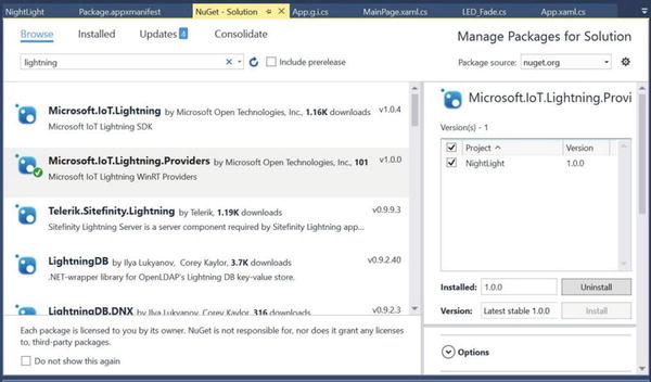
Figure 11-3. NuGet Package Manager
Select the entry named Microsoft.IoT.Lightning.Providers in the list, tick the project name (solution) in the list on the right, and finally, click Install. The installation starts. Visual Studio downloads a number of packages and then asks you permission to install them. Go ahead and let the installation complete. A dialog box tells you when the installation is complete.
Tip
You can also download this library and install it manually if the NuGet manager fails. See https://developer.microsoft.com/en-us/windows/iot/win10/lightningproviders for more details.
Since this library isn’t integrated with Visual Studio or the Windows UWP libraries, you must make a small alteration to the project files to grant permission to use the library (reference) in the project. Failure to do this step leads to some strange execution issues (but it compiles without errors or warnings). More specifically, the InitLightingProvder() method fails because the LightningProvider.IsLightningEnabled property is False.
In order to use the library, you need to manually update the Package.appxmanifest file to reference the Lightning device interface . To edit the file, right-click it in the Solution Explorer and then choose View Code. In the code editor, change the code at the top of the file as follows. I have noted the required changes in bold. The first line is a capability setting that enables the application to access custom devices and the second line is the globally unique identifier (GUID) for the lightning interface. Finally, you add iot to the namespaces list.
<Packagexmlns="http://schemas.microsoft.com/appx/manifest/foundation/windows10"xmlns:mp="http://schemas.microsoft.com/appx/2014/phone/manifest"xmlns:uap="http://schemas.microsoft.com/appx/manifest/uap/windows10"xmlns:iot="http://schemas.microsoft.com/appx/manifest/iot/windows10"IgnorableNamespaces="uap mp iot">...
Next, scroll to the bottom of the file and make the following changes. This adds the capabilities to match the changes at the top of the file.
...<Capabilities><Capability Name="internetClient" /><iot:Capability Name="lowLevelDevices" /><DeviceCapability Name="109b86ad-f53d-4b76-aa5f-821e2ddf2141"/></Capabilities></Package>
Now you’re ready to add code to initialize the lightning providers. Since you are using the lightning providers, you must initialize the provider library in the MainPageclass. The following method shows how to initialize the lightning provider.
private void InitLightningProvider(){// Set the Lightning Provider as the default if Lightning driver is enabled on the target deviceif (LightningProvider.IsLightningEnabled){LowLevelDevicesController.DefaultProvider = LightningProvider.GetAggregateProvider();}}
The bulk of the code for the SPI and PWM are contained in the new classes you will add shortly. But first, let’s implement the user interface and complete the MainPage class.
User Interface
The user interface is deliberately simple consisting of only a few labels and two sliders. The sliders control the minimum and maximum values for the range of sensitivity for the LDR. One of the labels displays the value read from the LDR. You can use this value to help tune the fade effect.
That is, you can set the lower value to the value read during ambient light levels. This effectively sets the percent power to 0 where the LED is off (or very dim). You can use the higher value slider to set the maximum value for the scale. You can find out what that value is by placing your hand over the LDR and reading the value. Thus, you can tune the night-light effect to match ambient light readings.
Listing 11-2 shows the code for the user interface. Open the MainPage.xaml file and make the changes as shown. This code uses a stacked panel to contain the controls. Note the lower value slider. You add a reference to a method to be called when the slider is updated. This helps you control the slider to avoid a nasty surprise should the lower value exceed the higher value. Speaking of which, I have added code to restrict the range to 0.0–1.0.
Listing 11-2. User Interface (XAML) Code
<Pagex:Class="NightLight.MainPage"xmlns="http://schemas.microsoft.com/winfx/2006/xaml/presentation"xmlns:x="http://schemas.microsoft.com/winfx/2006/xaml"xmlns:local="using:NightLight"xmlns:d="http://schemas.microsoft.com/expression/blend/2008"xmlns:mc="http://schemas.openxmlformats.org/markup-compatibility/2006"mc:Ignorable="d"><Grid Background="{ThemeResource ApplicationPageBackgroundThemeBrush}"><StackPanel Width="400" Height="400"><TextBlock x:Name="title" Height="60" TextWrapping="NoWrap"Text="Night Light Experiment" FontSize="28" Foreground="Blue"Margin="10" HorizontalAlignment="Center"/><TextBlock Height="60" TextWrapping="NoWrap"Text="High Value" FontSize="28" Foreground="Blue"Margin="10" HorizontalAlignment="Center"/><Slider x:Name="ldrHigh" Width="400" Value="350"Orientation="Horizontal" HorizontalAlignment="Left"Maximum="1023"/><TextBlock Height="60" TextWrapping="NoWrap"Text="Low Value" FontSize="28" Foreground="Blue"Margin="10" HorizontalAlignment="Center"/><Slider x:Name="ldrLow" Width="400" Value="125"Orientation="Horizontal" HorizontalAlignment="Left"Maximum="1023"ValueChanged="ldrLow_ValueChanged"/><TextBlock x:Name="status" Height="60" TextWrapping="NoWrap"Text="LDR Value = 0" FontSize="28" Foreground="Blue"Margin="10" HorizontalAlignment="Center"/></StackPanel></Grid></Page>
Figure 11-4 shows an example of the user interface.

Figure 11-4. Sample User Interface
The sliders can be moved independently. This presents a problem if the user slides the lower value to a setting greater than the higher value. Thus, you want to control the sliders so that the lower value never exceeds the higher value. To do this, you complete the code for the ldrLow_ValueChanged() method as follows. This illustrates a common technique to manage the range of user input.
private void ldrLow_ValueChanged(object sender, Windows.UI.Xaml.Controls.Primitives.RangeBaseValueChangedEventArgs e){// Make sure the low value doesn't exceed the high valueif (ldrLow.Value > ldrHigh.Value){ldrHigh.Value = ldrLow.Value + 1;}}
Tip
This code needs one extra step to ensure that you stay within the limits of the slider. See if you can spot it yourself. Hint: What happens when the high value is already at the highest setting? Although not essential for our experiment, you should strive to improve error handling to include the fringe values and conditions.
Now let’s see the code to read from the value of the LDR and fade the LED.
Controlling the LED
You are using a timer to refresh the project. This method, named refreshTimer_Tick(), first reads the value of the LDR from the MCP3008 class, and then calculates a percentage based on the minimum and maximum value scale as set via the user interface. You may have noticed that I used some constants values to set the initial range. Listing 11-3 shows the completed refreshTimer_Tick() method .
Listing 11-3. Timer Code
private void refreshTimer_Tick(object sender, object e){float valRead = 0;float brightness = 0;Debug.WriteLine("Timer has fired the refreshTimer_Tick() method.");// Read value from the ADCvalRead = adc.getValue(LDR_CHANNEL);Debug.Write("Val read = ");Debug.WriteLine(valRead);status.Text = "LDR Value = " + valRead;// Get min, max from slidersmin_LDR = (int)ldrLow.Value;max_LDR = (int)ldrHigh.Value;Debug.WriteLine("Min LDR = " + min_LDR);Debug.WriteLine("Max LDR = " + max_LDR);// Calculate the brightnessbrightness = ((valRead - min_LDR) / (max_LDR - min_LDR));// Make sure the range stays 0.0 - 1.0if (brightness > 1){brightness = (float)1.0;}else if (brightness < 0){brightness = (float)0.0;}Debug.Write("Brightness percent = ");Debug.WriteLine(brightness);// Set the brightnessfader.set_fade(brightness);// For extra credit, show the voltage returned from the LDR// convert the ADC readings to voltages to make them more friendly.float ldrVolts = adc.ADCToVoltage((int)valRead);// Let us know what was read in.Debug.WriteLine(String.Format("Voltage for value read: {0}, {1}v",valRead, ldrVolts));}
Wow, that’s a lot of code. For the most part, it is similar to the timer event from the last project. However, the calculation for the percentage to use for the PWM is new. Here the percentage represents the brightness of the LED. The higher the percentage calculated means the faster the LED pulses and therefore appears brighter.
I have added an interesting bit of data at the end of the method. This demonstrates how to calculate the voltage that is flowing through the LDR. You may need this technique for any projects where you are reading analog voltage.
Take some time to read through the code. You will see a number of additional debug statements that you can use when testing the project in debug mode. There is code to update the label in the user interface with the value read and the voltage calculated. If you are curious, you can use a multimeter to measure the voltage on the ADC side of the LDR (positive lead on the LDR and negative lead on ground). You should see the same voltage on the multimeter as shown in the user interface.
Now let’s see how to put all of these pieces together.
Completing the Main Class
Now that you’ve seen all the code for the main code file, let’s look at how the methods are placed in the class. Listing 11-4 shows the skeleton of the MainPage class. Use this as a guide to place the code in the right places. I omit the details of the methods for brevity.
Listing 11-4. MainPage Code Layout
...namespace NightLight{public sealed partial class MainPage : Page{...public MainPage(){...}private void InitLightningProvider(){...}private void refreshTimer_Tick(object sender, object e){...}private void ldrLow_ValueChanged(object sender,Windows.UI.Xaml.Controls.Primitives.RangeBaseValueChangedEventArgs e){...}}}
Now let’s see how to create the code for the two new classes.
Code for the MCP3008
The code for the ADC class is very similar to the class you used in the last project. The difference is you will use the lightning providers to communicate with the ADC rather than the Windows 10 IoT extension. This is because the Windows 10 IoT extension and the lightning provider are incompatible. That is, you cannot use the same code from the last project together with the PWM code from the lightning provider. Fortunately, the lightning provider has SPI support.
The methods that you use in this class are same as you had in the last project. The following summarizes the methods that you need. The last method is a bonus method that you may need in the future if you reuse this code for more advanced projects.
Constructor – MCP3008(): Log instantiation with a debug statement
Initialize(): Initialize the SPI interface
getValue(): Read a value from the ADC on a specified channel
ADCToVoltage (): Return the voltage read for a specific value
Recall from Chapter 10 that to add a new class, right-click the project and choose Add ➤ New Item.... Name the class MCP3008 to distinguish it from the similar class in the last project. When you create a class, you create a new file, as shown earlier. Inside this new code file, you see a familiar skeleton. Of note is the same namespace as the main code and a list of namespaces that you will use. Open the file now and add the following namespaces. The need for each is shown in the comments.
using Windows.Devices.Spi; // add this for SPI communicationusing System.Diagnostics; // add this for debugging
Next, you need some variables and constants. You need a variable for the SPI device and constants for the MCP3008. In this case, you set constants for helping you read data.
// SPI controller interfaceprivate SpiDevice mcp_var;const int SPI_CHIP_SELECT_LINE = 0;const byte MCP3008_SingleEnded = 0x08;const byte MCP3008_Differential = 0x00;
You also add a variable to store the reference voltage for the value read. You also store the maximum value of the component read from the ADC (1023). Of note is how I converted the constant 5.0 to a float by adding F to the end. This is a common shortcut that you can use instead of casting with (float). Also, be sure to change the reference voltage if you use a different voltage to power the components connected to the ADC channels. Recall from the wiring layout in Figure 11-1, you’re using 5V on the LDR.
// These are used when you calculate the voltage from the ADC unitsfloat ReferenceVoltage = 5.0F;private const int MAX = 1023;
The constructor is simple; you just announce that you’ve instantiated the class via a debug statement. You will see this in the class layout later in the section. The really interesting changes appear in the Initialize() method. Listing 11-5 shows the updated method that uses the lightning provider class methods.
Listing 11-5. The Initialize() Method
// Setup the MCP3008 chippublic async void Initialize(){Debug.WriteLine("Setting up the MCP3008.");try{// Settings for the SPI busvar SPI_settings = new SpiConnectionSettings(SPI_CHIP_SELECT_LINE);SPI_settings.ClockFrequency = 3600000;SPI_settings.Mode = SpiMode.Mode0;SpiController controller = await SpiController.GetDefaultAsync();mcp_var = controller.GetDevice(SPI_settings);if (mcp_var == null){Debug.WriteLine("ERROR! SPI device may be in use.");return;}}catch (Exception e){Debug.WriteLine("EXEPTION CAUGHT: " + e.Message + " " + e.StackTrace);throw;}}
This method is very similar to the class that you used in the last project. The biggest difference is you can get the SPI device with a single class to the provider. This code is a pattern for the other providers in the Lightning Providers library. In fact, you see very similar code in the PWM class.
The getValue() method is the same as the class used in the previous class. You can simply copy it from the last project and past it in the new class. I omit the details from the list for brevity.
Now, let’s see how all of these pieces fit together. Listing 11-6 shows the class layout for the MCP3008 class.
Listing 11-6. The MCP3008 Class Layout
...namespace NightLight{class MCP3008{...public MCP3008(){Debug.WriteLine("New class instance of MCP3008 created.");}// Setup the MCP3008 chippublic async void Initialize(){...}public int getValue(byte whichChannel){...}// Utility function to get voltage from ADCpublic float ADCToVoltage(int value){return (float)value * ReferenceVoltage / (float)MAX;}}}
Notice the last method. This is a helper method that you can use to calculate the voltage read from the channel. You used this in the MainPage class to display the voltage when the value is read from the LDR.
Tip
If you want to copy a class from another project, you can copy the file into the project folder and optionally rename the file. To add the class to the solution, right-click the project and choose Add ➤ Existing Item... and select the class file. If you renamed the class file, you may also have to rename the class itself as well as change the namespace to match the current project/solution.
Now let’s look at the code for the PWM class.
Code for the PWM
The code to implement PWM on a GPIO pin is very straightforward and models the code in the MCP3008 class. The following summarizes the methods that you need. The last method is a bonus method that you may need in the future if you reuse this code for more advanced projects.
Constructor – LED_Fade(): Log instantiation with a debug statement
Initialize(): Initialize the PWM interface
set_fade(): Set the duty cycle (percentage of time the LED is on) for the GPIO (LED) pin
Recall from Chapter 10, to add a new class, right-click the project and choose Add ➤ New Item.... Name the class LED_Fade. When you create a class, you create a new file, as shown. Inside this new code file, you will see a familiar skeleton. Of note is the same namespace as the main code and a list of namespaces that you will use. Open the file now and add the following namespaces. The need for each is shown in the comments.
using System.Diagnostics; // add for Debug.Write()using Windows.Devices.Pwm; // add for PWM control (10586 and newer)using Microsoft.IoT.Lightning.Providers; // add for Lightning driver for Pwm
There are only two variables required: one for the GPIO (LED) pin and another for the PWM class instance from the lightning provider. You use this variable to communicate with the PWM features.
// Variables for controlling the PWM classprivate int LED_pin;private PwmPin Pwm;
The constructor sets the pin number as a parameter and prints a debug statement indicating the instance has been created. The code is shown next.
public LED_Fade(int pin_num = 27){LED_pin = pin_num; // GPIO pinDebug.WriteLine("New class instance of LED_Fade created.");}
The Initialize() method is very similar to the same method in the MCP3008 class. In this case, you are setting up the PWM provider. Listing 11-7 shows the complete Initialize() method .
Listing 11-7. The Initialize() Method
// Initialize the PwmController class instancepublic async void Initialize(){try{var pwmControllers = awaitPwmController.GetControllersAsync(LightningPwmProvider.GetPwmProvider());var pwmController = pwmControllers[1]; // the device controllerpwmController.SetDesiredFrequency(50);Pwm = pwmController.OpenPin(LED_pin);Pwm.SetActiveDutyCyclePercentage(0); // start at 0%Pwm.Start();if (Pwm == null){Debug.WriteLine("ERROR! Pwm device {0} may be in use.");return;}Debug.WriteLine("GPIO pin setup for Pwm.");}catch (Exception e){Debug.WriteLine("EXEPTION CAUGHT: " + e.Message + " " + e.StackTrace);throw;}}
This code is a bit different than the SPI code. In this case, you need to open a pin for controlling the PWM and set the starting duty cycle (percent). In this case, you set it to 0, which effectively turns off the LED. Finally, you start the PWM class.
To control the fading effect, you provide a method named set_fade()that takes a floating point value (percent) that you use to change the duty cycle of the PWM. The following shows the complete code.
// Set percentage of brightness (or how many cycles are pulsed) wherepublic void set_fade(float percent){if (Pwm != null){Pwm.SetActiveDutyCyclePercentage(percent);Debug.WriteLine("Pwm set.");}else{Debug.WriteLine("Cannot trigger Pwm.");}}
Now, let’s see how all of these pieces fit together. Listing 11-8 shows the class layout for the LED_Fade class.
Listing 11-8. The LED_Fade Class Layout
...namespace NightLight{class LED_Fade{...public LED_Fade(int pin_num = 27){LED_pin = pin_num; // GPIO pin}// Initialize the PwmController class instancepublic async void Initialize(){...}// Set percentage of brightness (or how many cycles are pulsed) where// 100 is fast or "bright" and 0 is slow or "dim"public void set_fade(float percent){...}}}
That’s it! The code is complete and ready for compilation. Be sure to check the prior listings to ensure that you have all the code in the right place. Once you have entered all the code, you should then attempt to compile the code. Correct any errors that you find until the code compiles without errors or warnings.
Deploy and Execute
Now it is time to deploy the application! Be sure to fix any compilation errors first. Like you have with other applications, you want to compile the application in debug first (but you can compile in release mode if you’d prefer) and you must turn on the debugger on your board. You do this with the device portal.
Go ahead and power on your board. Be sure to connect a monitor, mouse, and keyboard so you can use the user interface. When ready, connect to the board to run the device portal, turn on the debugger, and then open the project properties to target the device and run with the remote debugger.
Recall from the Chapter 9, you must modify two settings: the Remote machine name and the Authentication Mode. Set the Remote machine name to the IP address of your device with the port specified by the remote debugger when you started it from the device portal. For example, my device gave me the port number 8116 so I use 10.0.1.89:8116. Set the Authentication Mode to None.
Now you can deploy your application. Go ahead and do that now. You can run the deployment from the Debug menu and when you do, you see the debug statements in the output window. Listing 11-9 shows an excerpt of the data you should see. When you start the debugger, the output window automatically opens and displays the debug output. If it does not, you can open the window manually and select debug from the drop-down menu.
Listing 11-9. Example Debug (Output Window)
...New class instance of MCP3008 created.New class instance of LED_Fade created.Setting up the MCP3008.GPIO pin setup for Pwm....Timer has fired the refreshTimer_Tick() method.commandBuf = 11280readBuf = 00239Val read = 239Min LDR = 235Max LDR = 384Brightness percent = 0.02684564Pwm set.Voltage for value read: 239, 1.168133vTimer has fired the refreshTimer_Tick() method.commandBuf = 11280readBuf = 00239Val read = 239Min LDR = 235Max LDR = 384Brightness percent = 0.02684564Pwm set.Voltage for value read: 239, 1.168133vTimer has fired the refreshTimer_Tick() method.commandBuf = 11280readBuf = 00238Val read = 238Min LDR = 235Max LDR = 384Brightness percent = 0.02013423Pwm set.Voltage for value read: 238, 1.163245v
Of course, you can run the application by starting it on your device using the Apps pane. You use the small triangle or arrow next to the application name to start it and the square icon to stop it or the trashcan icon to delete the application.
If everything worked correctly, you should be able to place your hand over the LDR and see the LED brighten. If it doesn’t (and there is a good chance it won’t), don’t worry. Conduct an experiment by clearing away anything that can cast a shadow on the LDR and take note of the value in the user interface. Let it run for a few minutes and note the values. You should see it bounce around a bit but should settle to within about 20–30 of normal. For example, in my office, the ambient light level value was about 220. Next place your hand over the LDR and note the change in value. Let the values settle and note the value range. In my office, the value was about 450.
Now, adjust the high value slider to the value when your hand was over the LDR and the low value to the value for ambient light. Once set, you can experiment with the LED brightness by slowly placing your hand over the LDR. The LED should go from a very dim setting to full (or nearly) brightness. It may take some additional runs to fine tune the high and low values but once set, the project acts as a light-sensing night-light. How cool is that?
Summary
IoT solutions often require using analog components. Moreover, you may need to control analog components by adjusting the voltage to the component. This often requires using additional libraries and features that may not be in the standard libraries. In this case, you had to use a special library named the Microsoft IoT Lightning Providers to get access to PWM and SPI interfaces.
You saw a number of new things in this project, including another way to use an ADC with an SPI interface, how to read values from an LDR, and how to use PWM to control the brightness of an LED. While the project itself is rather simplistic, the code clearly was not and it was a bit more code than you’ve seen so far.4
The next chapter continues the set of example IoT projects that you can use to learn more about building IoT solutions. You learn how to write code to read more sensors. In Chapter 12, you create a project to report weather data from several sensors, and then in Chapter 13, you learn how to collect and store the data generated.