
Chapter 6. Built-In Shader Effects
All modern games are rendered using a variety of shader effects, and the XNA Game Studio runtime comes with several built in effects. In this chapter you’ll learn about them, including:
• BasicEffect
• The built in effect interfaces
• DualTextureEffect
• AlphaTestEffect
• EnvironmentMapEffect
• SkinnedEffect
You’ve actually used built-in effects for the rendering you’ve done up until now, even if you didn’t realize it! In Chapter 4, “Introduction to 3D Graphics,” you learned about pixel shaders and vertex shaders, which are combined into an effect. Although an effect doesn’t have to have both a vertex shader and a pixel shader, you see the term effect used interchangeably throughout this book for the word shader. As mentioned before, a shader is a simple program that runs on the GPU (graphics hardware) that either manipulates vertices (the vertex shaders), pixels (the pixel shaders), or both.
XNA Game Studio 4.0 includes five built-in effects. BasicEffect has existed since the first version of XNA, and although the shader is quite complex, it provides the basic functionality you need to do common rendering. Version 4.0 includes four new built-in effect types, including DualTextureEffect, which supports rendering and blending two textures at once. The AlphaTestEffect is a simple shader for doing alpha tests. There is also the EnvironmentMapEffect that enables you to easily do environment maps (explained later), and the SkinnedEffect that enables basic character animations.
These five effects are guaranteed to work in any Reach profile game and work on all platforms. The same cannot be said for custom effects (which is discussed in Chapter 8, “Introduction to Custom Effects”).
Using BasicEffect
Because it has been around the longest, it makes sense to start with BasicEffect. This effect is anything but basic, and the various permutations of things it can do are downright mind boggling at times. However, we might as well dive right in! Start by creating a new game project, and add box.fbx to the content project. Declare both the model variable and a basic effect:
Model model;
BasicEffect effect;
Update your LoadContent method to instantiate these objects:

Loading the model has been done several times, and creating the basic effect is pretty simple as well. It takes in the graphics device as its only parameter. You also use the Projection and View matrix parameters on the basic effect to set up your default camera. Because you’re creating and manipulating your own effect (BasicEffect), add a DrawModel method that is similar to the previous chapter:
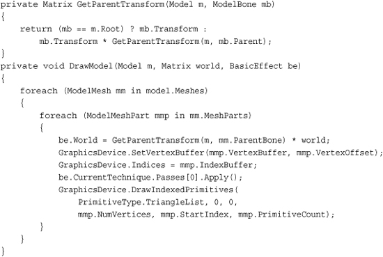
This takes the model you passed in and renders it using the supplied world matrix and basic effect. It uses the mesh parts of the model to render directly, using the graphics device rather than the Draw helper methods on the model. BasicEffect has only one pass for its rendering, so the for loop around the effect apply is not needed.
Note
BasicEffect is the default effect that is created for this model during content importing, but you use a new one for ease of these examples.
Finally, replace your Draw method to render the model, and notice an ugly white box on the screen, much like you see in Figure 6.1.
protected override void Draw(GameTime gameTime)
{
GraphicsDevice.Clear(Color.CornflowerBlue);
DrawModel(model, Matrix.Identity, effect);
}
Figure 6.1. An ugly, unshaded box

As you can see, the box is not visually appealing. It doesn’t even appear 3D! This is because it has no lighting on it, so everything has the same color, which means you can’t see edges that make everything appear flat. Adding a simple call to EnableDefaultLighting on the effect after you have set the view matrix makes your box appear 3D because it turns on lights and makes the different faces of the box shaded differently. You’ve seen the box like this many times before. So instead, let’s try something different.
Basic Lighting
If you added the call to EnableDefaultLighting, remove it and add the following after the view matrix is set in LoadContent:
effect.LightingEnabled = true;
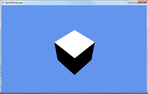
This tells the effect to enable the lightning engine. Now run the application, and notice a similar shape as the first time you ran this application, but there is a bright white square in the center followed by the other portions of the block looking flat and black as in Figure 6.2.
Figure 6.2. Default lighting
To understand how enabling lighting made portions of the box turn pitch black, first take a basic look at how lighting works. Basic effect gives you four different functions of lights for you to modify: an ambient light, directional lights, specular highlights, and the emissive color.
The ambient light is the easiest to visualize and understand. You can think of ambient light as the light that is always on, always around, comes from every direction, and lights everything equally. Notice an AmbientLightColor property on BasicEffect that defaults to black, which is why the sides of your box look pure black. Add the following line after enabling the lights in LoadContent:
effect.AmbientLightColor = Color.Purple.ToVector3();
Running the application now changes the black portions of the box to purple because that is the color of the ambient light. The top of the box is still bright white.
Note
Notice that all colors used in the built-in effects are not Color objects, but vector objects. The x, y, and z components of the vector object map to the red, green, and blue color components where 0.0f is fully off and 1.0f is fully on. Vector3.Zero is pure black, and Vector3.One is pure white. The Color object also has two helper methods, ToVector3 and ToVector4, to easily get the appropriate data.
Changing the ambient light color to another color shows you that the portions of your box that were originally black and are now purple change to the color you are using as the ambient light color. If you change it back to white, you are back to where you started with a pure white square-like shape. That’s because of the next light type, directional lights.
As the name implies, directional lights come from a certain direction. The sun is a good example of a directional light conceptually. The light goes in a particular direction infinitely without becoming more dim the farther away it goes, and without having a real source. Although the sun doesn’t meet these criteria, from the perspective of the Earth, it is close enough. The built-in basic effect has support for up to three different directional lights, and by default, only the first one is enabled. These lights are accessed via three separate properties called DirectionalLight0, DirectionalLight1, and DirectionalLight2. Each directional light has a few properties that are interesting to look at, too.
First, the directional light has an Enabled property to determine whether it is on or not on. Much like the ambient light color, there is a DiffuseColor property that is the diffuse color of the light (you can think of this as simply the color of the light). This property defaults to pure white (Vector3.One), which is why the top of the box currently as white. A directional light also needs to have a Direction property that defaults to Vector3.Down, which also explains why the top of the box is pure white. The final property is the SpecularColor, which we discuss later in the chapter.
By switching LightingEnabled to true, you not only turn on lighting, but you also get the defaults for all of the lighting-centric properties, so a black ambient light and a single directional light turned on, pointing straight down with a white light. This explains the appearance of the box.
If you switch the direction, notice the box is lit differently. For example, add the following line after enabling the lights:
effect.DirectionalLight0.Direction = Vector3.Left;
This causes the top of the box to turn black again (the direction is no longer on top of it), but the right side of the box to turn white. This is because the direction of the light moves to the left, causing the right side to illuminate. If you use Vector3.Right, a pure black box appears because the left side of the box is lit, but you cannot see that side from where your camera is. Of course, having only one side of the cube light up isn’t interesting, so change the direction slightly such as the following line:
effect.DirectionalLight0.Direction = Vector3.Normalize(new Vector3(-1,-1,0));
Both the top and the right portions of the box are now gray. Notice that you normalized the vector before passing it into the direction, because Direction is required to be a unit vector (meaning that the length of the vector must be one, which is also what Normalize does). The top and side are the same color gray because the angle between the direction of the light and the normal of the face is the same on each side with that vector (equally lighting the right and top faces). Change the direction to the following line:
effect.DirectionalLight0.Direction = Vector3.Normalize(new Vector3(-1,-1.5f,0));
All three sides of the cube now have different colors with the top as the lightest gray, the right as a dark gray, and the front as completely black.
Lighting Calculations
The final color of each piece of your model when it is lit comes from a wide variety of sources. Directional light is calculated using the dot product of the direction vector and the normal vector for the current face. The normal vector is perpendicular to the plane of the face. Without normal vectors, all lighting calculations (aside from ambient, which is everywhere equally) would not work. The color of the light is scaled by the dot product. That color is combined with vertex colors on the model, textures that are being rendered, and the ambient light.
If you change the color, the light changes to that color. Add the following line after setting the direction:
effect.DirectionalLight0.DiffuseColor = Color.Yellow.ToVector3();
The box is now a yellow color. If you use the previous direction, the top of the box is a light yellow, the right is a dark yellow, and the front is pitch black. This is because there is no light on the front of the box and it uses the ambient color (see Figure 6.3).
Figure 6.3. A box lit by a single directional light

The basic effect class supports up to three different directional lights. These lights can be turned on all at once, one at a time, or not at all. Just because they happen to be named in a numeric order doesn’t mean you have to use them in that order. For example, add the following lines after your current light settings in LoadContent:
effect.DirectionalLight1.Enabled = true;
effect.DirectionalLight1.DiffuseColor = Color.Blue.ToVector3();
effect.DirectionalLight1.Direction = Vector3.Left;
This is setting the second of the directional lights basic effect uses to a blue color pointing to the left. Running the application shows you that the top square of the box is the same dark yellow color, and the right side (which now has a light yellow light as well as a solid blue light) is an odd purplish color. This is because the two light colors blend together. You can tell this by setting the DirectionalLight0.Enabled property to false and see that the right face is now a solid blue because it isn’t combined with the yellow light. Set it back to true, so you can see the combination of all three lights. Replace your lightning code with the following lines:
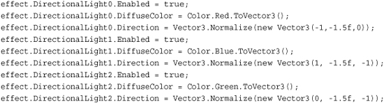
This takes three different lights: red, green, blue, shining all on the box in different directions. Each light hits more than one face, so you see a combination of the colors (mostly red on the right face, a pinkish color on the top face, and mostly blue on the front face). Each of these lights can be controlled individually or combined.
There is also a helper method on BasicEffect called EnableDefaultLighting, which sets up a standard lighting rig. This is actually not something unique to games or even 3D graphics. Photographers and movie makers discovered long ago that taking pictures of things looked much better when using more than one light and specifically, they looked best with at least three lights (this is also why this class supports three lights).
This is normally done with a key light that is the brightest of the lights and is pointed directly at the subject. A fill light that is dimmer also points at the subject, although usually at a ninety degree angle from the key light. This light helps balance out the image by illuminating some of the shadows that are too dark from the key light. Finally, the backlight, which as the name implies, shines from behind the subject to help separate him or her from the background and to give subtle detail. The back light is normally the dimmest light.
With all the basics of directional lighting out of the way, let’s move on to the other major light, specular lighting. This is used in the standard lighting rig that the EnableDefaultLighting helper method creates for you. What are specular highlights?
A specular highlight is the bright spot on an object. It makes objects appear shiny. You can’t see this on a box though, so let’s make a few changes to the current project. First, delete the lighting code you added so far (you should just have the world and view matrices set on the effect). Next, add the sphere.x object from the downloadable examples to your content project. It is much easier to see this effect on a sphere. Finally, change your model loading to use the sphere rather than the box.
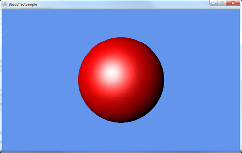
Run the application and notice a white circle in the middle of your screen, much like you saw the box before. Again, this is because there are no lights in the scene anymore. So first, turn on a directional light, so you can see the sphere as a sphere, not a circle, as follows:

The sphere looks like a sphere rather than a circle, but it doesn’t have a shiny look. This is because the specular color of the directional light defaults to black, so you do not see it. Add the following line directly after setting the direction:
effect.DirectionalLight0.SpecularColor = Color.White.ToVector3();
This turns on the specular color to a full white color, and much like you see in Figure 6.4, your sphere now has a bright white spot on it.
Figure 6.4. A sphere with a specular highlight
The specular color is much like the other colors because you can combine it with any of the others. The white specular light is combined with the red diffuse light and forms the bright spot. If you change the specular color from white to blue, notice that your white spot turns more purplish (the red diffuse light and the blue specular light combine to a purple color). Each directional light in the effect includes a specular color.
There are two other properties of specular lighting that are on the effect itself, not on any of the directional lights:the SpecularColor of the material and the SpecularPower of the effect. The power property is a float value that determines how concentrated the shiny spot is. Higher values make the effect more concentrated (a smaller spotlight on the sphere), and larger values lower the concentration and make the spotlight effect larger.
To see this behavior in action, add the following code to your Draw method before the DrawModel call:
effect.SpecularPower = (float)gameTime.TotalGameTime.TotalSeconds * 2.0f;
This starts the specular power at 0 (and your sphere looks almost completely white) and raises it higher as the application runs (it gains a power of 1.0f every half second). Notice that the spotlight effect quickly concentrates from the full sphere to a smaller spot, and then slowly gets more concentrated to a small point if you let it run long enough. Remove the line and let’s talk about the specular material color.
The SpecularColor on the effect is the color that is reflected by the lights. The default of this property is white, so all color is reflected making the spotlight effect white. Add this line after setting the light’s specular color in the LoadContent method:
effect.SpecularColor = Color.Red.ToVector3();
This reflects only the red light of the white specular light. If you run this, the sphere looks similar to before, but rather than a bright white spot, you see a red spot instead. If you change the SpecularColor on the directional light to a color without red light, for example, say blue, the specular effect completely disappears. This is because there is no red light to reflect a pure blue light and no specular effect.
Notice that you can see portions of how the sphere was created in the light because the vertices of the sphere stick out in the spotlight effect. This is because colors are determined by default per vertex, which show you these vertices when they’re close. If your graphics card can support it, you can have this effect do its lighting calculations per pixel rather than per vertex to give a much more smooth (and realistic) effect.
Add this line to the end of your lighting code in LoadContent to turn on per pixel light if your system supports it:
effect.PreferPerPixelLighting = true;
Notice that the spotlight is smooth. See Figure 6.5 for a comparison between per vertex and per pixel lighting.
Figure 6.5. Per-pixel and per-vertex comparison

Note
Per pixel lighting can look amazing, but at a cost. On Windows Phone 7, this process can hinder performance. This is discussed more in depth in Chapter 11, “Understanding Performance.”
The last lighting property is the EmissiveColor of the material. Unlike the specular material, this color is not reflected. It can be thought of as the color of light that the object actually emits. The default value of this is a pure black color (the object doesn’t emit anything). To see how this affects your sphere, replace your lighting code in LoadContent (after view and projection matrices are set) with the following:

This makes a sphere lit with a single white directional light. To make the sphere emit some red light, add the following line:
effect.EmissiveColor = Color.Red.ToVector3();
Notice a vastly different sphere. The dark portions without the emissive color are now bright red, and they lighten to white as the light from the directional light takes over. If you switch the color of the directional light to blue, it lightens to purple instead of white, because the blue light is combining with the red light to form purple.
Textures, Vertex Colors, and Fog
The basic effect also handles rendering a texture. If the model you are loading from the content pipeline includes textures, they are included as part of your model and rendered automatically. If they aren’t included, you can control that directly through the effect. To do this, add a new texture variable:
Texture2D texture;
To include a texture to load, add the file cat.jpg from your content project. Next, in your LoadContent method, switch the model you’re loading back to the box you used earlier. Remove the lighting code you used for the emissive color example, and create the texture and set it to the effect, as follows:
texture = Content.Load<Texture2D>("cat");
effect.TextureEnabled = true;
effect.Texture = texture;
Running the application shows you the box again, except this time you see each face of the box covered in the cat (see Figure 6.6).
Figure 6.6. A textured box
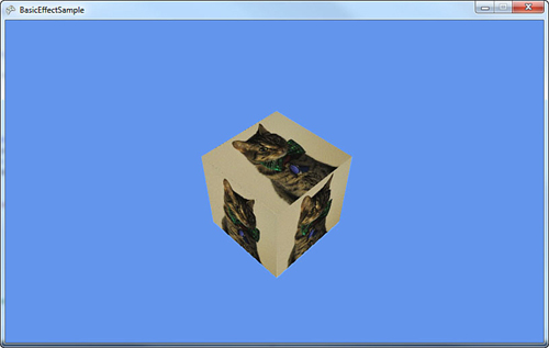
Notice that each face of the box looks the same. Because you’re using BasicEffect, you can use the other features as well. Add the standard lighting rig in your LoadContent method:
effect.EnableDefaultLighting();
The top of box is now slightly lighter than the other two faces due to the lighting. If you had a different model, you would see the specular highlights on it. You don’t see them because you rendered a cube, which has only a small number of vertices.
You’re almost done with the BasicEffect class. You can also use this effect for rendering vertex colors that are baked into the model. First, delete the code in your LoadContent method after the view and projection matrices are set, and add the following line:
effect.VertexColorEnabled = true;
This turns on the mode to render with vertex colors enabled. If you run the application, you see a black square-like blob. This is because the box model has no vertex colors in it. Let’s modify the model to add vertex colors. Add a new vertex buffer variable that will hold the updated data:
VertexBuffer vb;
Before you create the vertex buffer to hold the updated data, define the structure for what kind of data it will hold. The structure does not exist, so you need to create it. Add the following lines to your project:

Whew, that’s a lot of information, so let’s break it down. First, notice that the structure expects to implement IVertexType. This is used to describe the data to the graphics device, and has only one method to get the VertexDeclaration. Next, you have the actual data you want to store. The current box has three pieces of data it stores: the position of each vertex, the normal of each vertex, and the texture coordinates of each vertex. You keep these three, but you also add the color.
Next, you create a static VertexDeclaration (so you don’t create a new one every time you use the property that the interface implementation requires). This is done by describing the data this structure has in a language the graphics device understands. This is done through an array of VertexElement, with each of the members in the array describing a piece of the data that will be held. Let’s look at the VertexElement constructor that’s used here.
The first parameter of the constructor is the offset of the data (in bytes) from the beginning of the vertex. For the first member, use zero; for the second member, use 12. This is because the first piece of data is a Vector3, which contains three floats that are each four bytes large, and three times four is 12. The others are calculated in the same manner. The second parameter in the constructor is the format of the data. In your first two members, your data is in the Vector3 format. Your third member is a Vector2, and the last is a Color. This parameter tells the graphics device how much data is required for each member.
The third parameter of the constructor is how the effects will use this data. In the first member, it is a Position, the second is a Normal, the third is a TextureCoordinate, and the last is a Color. You can ignore the last parameter for now—just use zero.
There is then a constructor on the structure itself taking in the data type of vertices in the model, VertexPositionNormalTexture, which uses the old data. This constructor simply sets the default color to white, and then uses the data from the passed in structure to fill out the current structure.
This describes the new data, so let’s take a look at creating the vertex buffer and filling it up with good data. Add the following lines to the end of your LoadContent method:
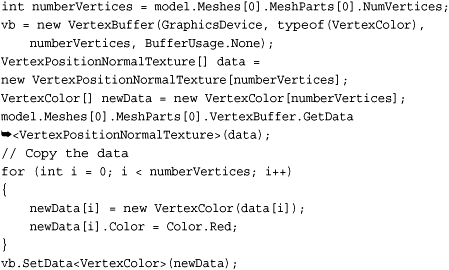
The box model you used has exactly one mesh with one mesh part in it, so getting the total number of vertices here is easy. You have to do a bit more work to make this more generic, which is beyond the scope of this example. You can then create your new vertex buffer using the type of structure you previously defined that dictates what type of data you’re using.
Now you need to get the old data from the model. First, create two new arrays of vertices: one of the type VertexPositionNormalTexture, which is the type of data currently in the model, and the other of type VertexColor, the new data you use. Then, you can simply call the GetData method passing in the first array to have the model’s data push into that array. You then can use the for loop to go through each of pieces of old data, filling up the new data and setting the vertex color to red. Finally, call SetData on your vertex buffer to fill it with the newly created data including the vertex color.
You’re not quite ready to render yet because your current DrawModel call uses the model’s vertex buffer, not the one you just created. Add the following method to draw with a specific vertex buffer:

This is almost identical to the previous DrawModel call; it uses the passed in vertex buffer instead. Update your Draw method to call this instead of DrawModel, and notice the black box is now a red box. However, just like everything else, this effect can be combined with all the other effects. For example, to see the box shaded by the standard lighting rig, add the following line after your SetData call in LoadContent:
effect.EnableDefaultLighting();
You can texture this as well by adding the following code:
texture = Content.Load<Texture2D>("cat");
effect.Texture = texture;
effect.TextureEnabled = true;
Now, the box with the cat picture has everything shaded red. If you change the previous vertex color to blue, everything is shaded blue.
The last thing to talk about is the fog effect. Your project is a bit crowded, so to show this, replace your LoadContent method with the following lines:
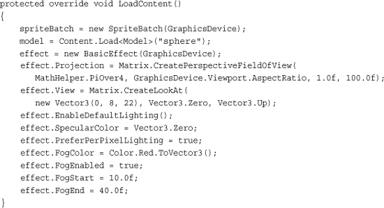
The majority of the previous code should be old hat by now. You switched back to the sphere to see the effect slightly better. You modified the view matrix to be a little bit higher and quite a bit farther away, and then turned on the standard lighting rig. Setting the specular color back to black isn’t necessary, but it’s easier to see the effect without the specular highlights.
Next, let’s set the four fog parameters. Enabling the fog is pretty straightforward, as is setting the color. The start and end parameters determine where the fog effect starts and where it ends, although “end” is a bit of a misnomer. These numbers are distances from the camera, where everything closer than the start value has no fog effect, everything beyond the end value has the full fog effect, and everything in between those values scale linearly between no effect and full effect.
It is easier to visualize this by seeing it in action, so let’s update the Draw method to render some spheres. Delete everything from this method except the Clear call and add the following lines:
const int NumberSpheres = 55;
for (int i = 0; i < NumberSpheres; i++)
{
Matrix world =Matrix.CreateTranslation(
((i % 5) - 2) * 4, 0, (i/5-3) * -4);
DrawModel(model, world, effect);
}
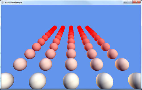
This renders a set of fifty-five spheres across the screen (you can change the constant to lower/raise the amount you are rendering). The spheres start close to the screen, and every set of five moves the next set a bit farther from the camera. Eventually, as you get ten units away, the spheres start having a red tint. The farther way they get from the camera, the moreof the tint they get until they’re completely red (see Figure 6.7).
Figure 6.7. A first look at fog
Fog adds another way to set the final color of objects in the world. By using fog, you can make objects appear to “disappear” the farther away they are. Using red doesn’t make that apparent, but go back and change the FogColor in your LoadContent method to CornflowerBlue. Much like you see in Figure 6.8, the farthest spheres simply disappear, while the ones in the fog range appear to be faded.
Figure 6.8. Spheres disappearing in fog

As before, all of these effects that BasicEffect uses can be combined with each other. To show this, switch your model back to the box, and add the following to the end of the LoadContent method:
texture = Content.Load<Texture2D>("cat");
effect.TextureEnabled = true;
effect.Texture = texture;
Notice your spheres are replaced with boxes that have pictures of cats on them, and they slowly fade out into the distance (see Figure 6.9).
Figure 6.9. Textured boxes disappearing in fog

As you can see, BasicEffect does quite a bit. Before moving on to the other built-in effects, let’s take a few minutes to see the interfaces it uses.
Using the Effect Interfaces
BasicEffect implements three different interfaces that are generic enough to be used by multiple types of effects. Each of the built-in effects in Game Studio 4.0 uses at least one of these interfaces, and your own custom effects could also. This enables you to easily cast your effects to these interface types to do common operations. The most common is the following:
public interface IEffectMatrices
{
Matrix Projection { get; set; }
Matrix View { get; set; }
Matrix World { get; set; }
}
This is to give you a spot to set your matrices generically. As expected, there is also one to handle basic lighting:
public interface IEffectLights
{
Vector3 AmbientLightColor { get; set; }
DirectionalLight DirectionalLight0 { get; }
DirectionalLight DirectionalLight1 { get; }
DirectionalLight DirectionalLight2 { get; }
bool LightingEnabled { get; set; }
void EnableDefaultLighting();
}
Finally, there is an interface you can use if your effect supports fog:
public interface IEffectFog
{
Vector3 FogColor { get; set; }
bool FogEnabled { get; set; }
float FogEnd { get; set; }
float FogStart { get; set; }
}
All of these interfaces are used by the built-in effects and are there for you to implement in your own custom effect classes to write generic code for many common operations. Now let’s move on to the next built-in effect type.
Using DualTextureEffect
You might have noticed that while using BasicEffect, you can use only a single texture. The DualTextureEffect enables you to use two. A common use of a dual texture is for either light maps or decals. This effect implements IEffectMatrices and IEffectFog, but not IEffectLights, so you don’t get lights here! Because a common use of this is for light maps, that makes sense, too. Let’s see it in action. Create a new project and add a few files in your content project. Add the model (dualtextureplane.fbx), the first texture (ground.jpg), and the light map (lightmap.png). Also add a couple new variables to your project:
Model model;
DualTextureEffect effect;
To show this effect, render a single plane with a texture on it (it can be the “ground”). To do this, add the following code to your LoadContent method:

This loads your model and effect and sets up your camera. It also sets the first texture and updates the diffuse color (the default is bright white). You need to add a DrawModel call to use this effect, so add that as follows:
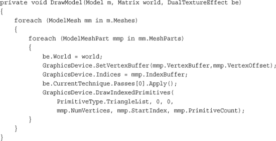
This is similar to your last DrawModel call, except without the generalization of enabling a hierarchy of world transforms, it simply sets the effect and draws the geometry. Now include a call to this method in your Draw call:
DrawModel(model, Matrix.Identity, effect);
After you run this, you expect to see the plane rendered on the screen with the single texture showing up, but all you see is a black square. This is because you don’t have the second texture loaded, and the default color it returns if the texture isn’t there is black. It then combines the two colors from the textures, but black combined with anything else gives you black, so you see nothing. Temporarily set your second texture to light grey using the following code at the end of your LoadContent method:
effect.Texture2 = new Texture2D(GraphicsDevice, 1, 1);
effect.Texture2.SetData(new Color[] { new Color(196, 196, 196, 255) });
This shows you the plane rendered on the ground with a single texture. Well, it is two textures, with the second texture as a single light gray pixel. Not hugely exciting, but if you add this line to the end of your LoadContent method, the second texture is loaded, and running the application makes the ground appear to have spotlights on it (see Figure 6.10):
effect.Texture2 = Content.Load<Texture2D>("lightmap");
Figure 6.10. Spotlights with DualTextureEffect

You can also set effect.Texture to the single light gray pixel and see the light map rendered alone on the plane. With this effect, you can perform quite a range of techniques using two textures, and light maps as one of them!
Using AlphaTestEffect
At a high level, the AlphaTestEffect enables you to get performance benefits by quickly (and early) rejecting pixels based off their alpha level. There are only a few things important on this effect, so we won’t have a large example here.
Like the DualTextureEffect, AlphaTestEffect implements the IEffectMatrices and IEffectFog interfaces. There are two important properties on this effect: first is the AlphaFunction, which describes how to compare the alpha, and second is the ReferenceAlpha, which is what each pixel’s alpha component is compared to (using the AlphaFunction).
The CompareFunction enumeration has a variety of ways each pixel can be compared to the ReferenceAlpha, and if the compare function evaluates as true, that pixel is accepted, processed, and potentially rendered. If you use the Always value, all pixels are accepted much like the Never value accepts no pixels. Each of the others behaves as expected with Less, LessEqual, Equal, Greater, GreaterEqual, and NotEqual.
Using EnvironmentMapEffect
Have you ever seen (either in the real world or in a game) a brand new car sitting outside on a bright and sunny day? Did you notice how the car looked so shiny? Did you notice how the car reflected the outside world on itself? This effect is called the EnvironmentMapEffect because you map the environment onto an object. Like BasicEffect, this effect implements all three interfaces.
Environment maps are done by rendering a cube texture (the TextureCube class) as a reflection over any objects that need to have the reflection. A cube texture is (as the name implies) a texture that covers a cube, so it has six different faces. However, it covers the inside of the cube. The effect is rendered as if the object is sitting inside the cube with the texture reflecting off the object.
To show this effect, create a new game project. Add some content from the downloadable examples to your content project. You need the model that you will render the reflection, so add the environmentmapmodel.fbx model. Add the six textures the skybox will use (skybox0-5.jpg).
Next, add a few variables:
Model model;
EnvironmentMapEffect envEffect;
TextureCube texture;
Like always, you’ll need to instantiate these variables, too, so update your LoadContent method by adding the following:

The beginning of this code is familiar: Load the model, create the effect, and set up the camera. You then need to create a new TextureCube object that is used as your environment map, and that needs to be filled with data.
Note
In a real game, you probably wouldn’t want to load your cube texture (environment map) in this manner; you would use a custom content pipeline processor. The Content Pipeline will be discussed in depth in Chapter 9, “Using the Content Pipeline.”
To easily fill the environment map with data, load each face of the cube map into its own temporary texture and copy the data to the appropriate face of the cube texture. After the cube texture has data, set the parameters for the effect and you’re ready to start rendering.
The Texture parameter, much like BasicEffect, is simply the texture the object is supposed to have, what it would look like without reflections. The EnvironmentMap parameter is the cube texture that contains the reflection data, and EnvironmentMapAmount is a float describing how much of the environment map could show up (from 0.0f, or nothing, to 1.0f, or the max). The default amount is 1.0f.
The FresnelFactor parameter describes how Fresnel lighting should be applied to environment map, independent of the viewing angle. With a low value, the environment map is visible everywhere. With a value of 0.0f, the environment map covers the entire object, and a large value shows only the environment around the edges. The default value is also 1.0f.
The EnvironmentMapSpecular parameter is a bit special. It blends the alpha from the environment map into the final image using this value. This enables you to embed maps into your environment map to have cheap specular highlights (rather than having to actually use the GPU to render more lights). Even though it is set, its default value is also Vector3.Zero.
Lastly, enable the standard lighting rig. Now you’re ready to render this model. Include the DrawModel method you used several times so far.
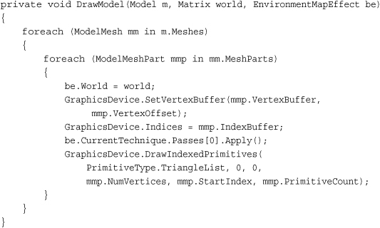
Finally, to see how the model reflects the environment map, add the following lines to the Draw method and see your reflection map (see Figure 6.11).
float time = (float)gameTime.TotalGameTime.TotalSeconds;
DrawModel(model, Matrix.CreateRotationY(time * 0.3f) *
Matrix.CreateRotationX(time), envEffect);
Figure 6.11. An environment map
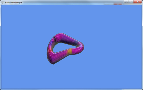
As the model rotates, you can see the reflection of the environment around it. Manipulating the EnvironmentMapAmount parameter as well as the FresnelFactor parameter changes how much reflection you see. With that, let’s move on to the last of the built-in effects.
Using SkinnedEffect
Much like BasicEffect and EnvironmentMapEffect, SkinnedEffect implements all three of the standard interfaces: IEffectMatrices, IEffectLighting, and IEffectFog. This section focuses only on the new pieces of functionality. This effect is primarily used to enable you to render animated objects (or “skinned” objects).
Animation for a particular model is normally stored within the model itself and is included when you are importing and processing the model. However, by default, you won’t be able to get this data at runtime, so you need to build a content processor to store this data.
Note
Content importers and processors are discussed more in depth in Chapter 9—think of this as a crash course for a processor.
This appears to be the most complex example you’ve seen so far, but despite the number of projects, it isn’t that complicated. First, you need the actual example project, so create a new game project called SkinnedEffectExample. You also need two other projects though: your content processor project and another game library project to hold these shared types.
In your solution, you should have two projects: the SkinnedEffectExample game project and the SkinnedEffectExampleContent project. Right-click your solution file in Visual Studio, select Add -> New Project, and then choose a Game Library project that will hold all of the shared types between your game and the content processor. You can call this one SkinningInformation. Lastly, right-click the solution again in Visual Studio and choose Add -> New Project, but this time choose the Content Pipeline Extension Library. You can call this SkinnedModelProcessor.
To make sure that both your game and the content processor have access to your shared data types, right-click the References node (located under your SkinnedModelProcessor project) and select Add Reference. Choose the Projects tab, and select your SkinningInformation project. Next, do the same thing for the SkinnedEffectExample project, and now you’re basically ready to get started.
To add the shared data types, remove the class1.cs from your SkiningInformation project, right-click the project, select Add -> New Item, and choose a new code file called SharedTypes.cs. Add the following code to that file:

The first shared type is a KeyFrame. This is essentially the state of a bone at a given point in time. Remember that the bone describes the transform of a particular portion of the model. By using key frames, a model can define a wide variety of animations by simply having the bones placed at particular places in time.
Next, you need another piece of shared data, so add the following lines to the code file:
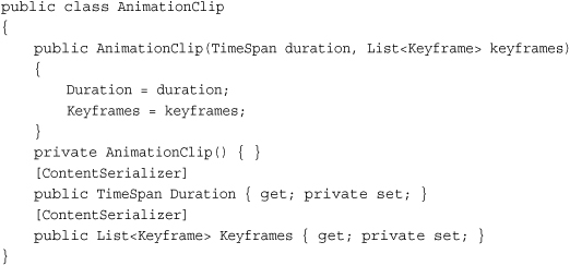
This defines the total animation as a list of key frames. The duration is the total length of animation, and the key frames are also stored. Because this class is self-explanatory, add another shared type here:

This is the data type that holds the animations for use at runtime. It has a few properties, namely a list of animation clips that the model supports along with the bind pose, the inverse of the bind pose, and a skeleton hierarchy. The bind pose is the “pose” of the model before any animation occurs (where the inverse is, of course, the inverse of this). The skeleton hierarchy is the list of indices into the bones.
Notice that many of the properties in these shared data types include the ContentSerializer attribute. This is discussed later in Chapter 9.
There is one more type to add before you can start with the processor. Add the following class:

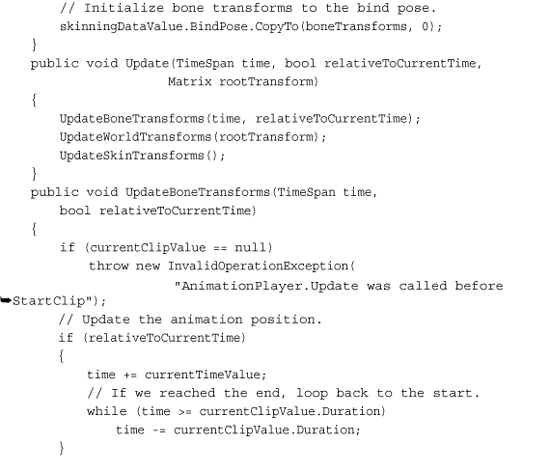


Well, that was a lot of code! Use this class to control the currently playing animation for your model. It has a few pieces of data it needs, starting with the current clip that is played, the current time in the animation, and the current key frame used. It also includes three sets of matrices used to control the animation model and the previously defined SkinningData information.
This object is created from a SkinningData object, and the constructor validates the data and creates the arrays of matrices that are used. The next method is StartClip, which tells the animation player to start a new set of animation. This method resets the current animation members, and then copies the bind pose transforms to the bone transforms.
As your animation plays, the various matrices need to be updated, so the Update method does exactly this. It takes in the amount of time that has elapsed, whether or not the time is relative to the current time, and the root transform of the animation. This in turn calls three helper methods to update the sets of matrices.
The first of these helper methods updates the bone transforms by looking at the list of key frames. First, it checks the time, does a few parameter checks, determines whether the animation has reached the end (and loops back to start if it has), and then begins looking through the key frames. It sets the bone transforms for the key frames required, and then exits the loop. These key frames come from the model during content processing.
Next, it updates the world transforms, which is nothing more than transforming the root bone by the root transform passed in to update, then transforming each child bone by its bone transform and its parent’s bone transforms.
For the last of the helper methods, it updates the skin transforms by transforming the inverse bind pose of each bone with the world transform. Finally, there are a few extra methods and properties to expose the private members publicly.
With the shared types out of the way, you can actually create your content processor now to get the animation data into your game.
Go to your SkinnedModelProcessor project, remove the code file it created, and add a new one called SkinnedModelProcessor.cs. First, add the following code:
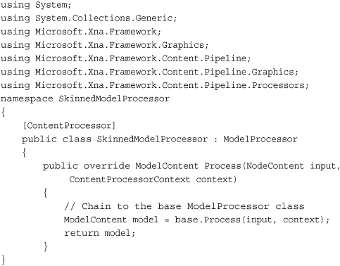
Although this isn’t exciting, it is the basis for the processor you create next. You created a new content processor, and it is derived from the already existing ModelProcessor. In the Process method (currently), call the base Process method to get all the model data and return it. Although this does nothing more than the ModelProcessor (yet), it now has the infrastructure to do so.
To get the animation data through, add the following as the first line of code in your Process overload:
ValidateMesh(input, context, null);
This method validates the mesh, however, it doesn’t exist yet, so let’s add it to the class:

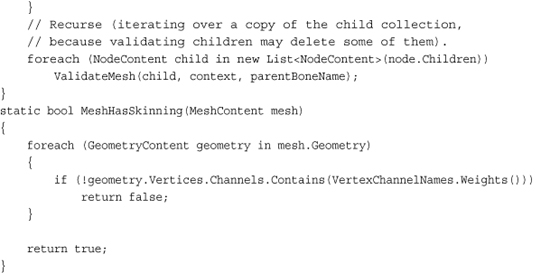
This method uses a helper method defined at the end to determine whether the mesh has skinning information. It does this by looking through each piece of geometry to see whether it has a vertex channel called Weights. If it does not, it assumes it has not skinning information. Meanwhile, in the actual method, it determines whether this is a valid mesh.
As it checks the parameters, if it finds problems, it uses the context.Logger property to log warnings. This class is part of the content pipeline that runs during build time, so these logged warnings show up in the Visual Studio IDE as warnings during build time.
First, this method checks whether the node is a mesh and if it is, it performs two checks. It determines whether the mesh is a child of a bone and log a warning if so because this processor isn’t equipped to handle that scenario. Next, it checks whether the mesh has skinning information and if it does not, it removes itself and logs a warning.
If the current node being checked isn’t a mesh, it stores the bone instead because the bone is naturally the parent for all children of this node. After it checks these parameters, this method also recursively iterates over the entire list of children to validate that they’re all valid meshes.
In the Process override, add the following code after your ValidateMesh call to get the animation data:
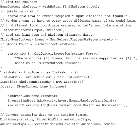
First, find the skeleton with the built-in helper method FindSkeleton. If one isn’t found, this model doesn’t have the data this processor needs, so an exception is thrown (which shows up as an error in the Visual Studio IDE). After that, use the following FlattenTransforms helper method:
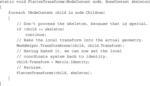
This recursively looks through all nodes in this piece of content and transforms the portions of the scene into the same (local) coordinate system. This makes dealing with the various transforms much easier. Next, you get the bind pose of the skeleton and throw an error if it has too many bones for this effect. Then, create the three lists you need to maintain the animation data, and fill them with the appropriate information. Finally, create a set of animation clips to store with the following ProcessAnimations helper methods:
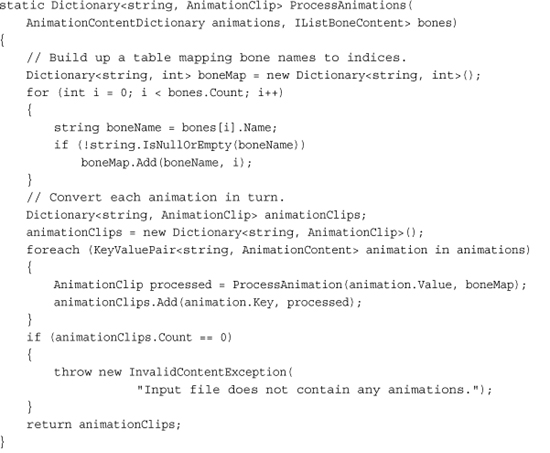
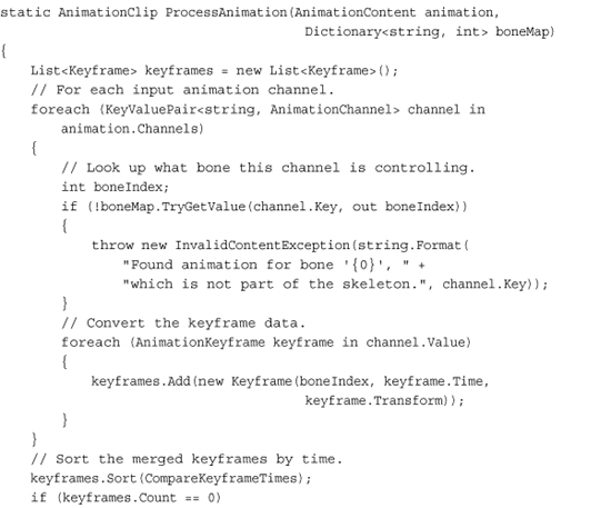

The helper methods go through the animations listed on the skeleton and convert them into a list of key frames sorted by time. If there are errors found during this conversion, exceptions are thrown to notify the user during build time; otherwise, the list of animations is returned.
Finally, store this data back into the model before you return it from being processed. So at the end of the Process override, before you return the model, add the following code:
model.Tag = new SkinningData(animationClips, bindPose,
inverseBindPose, skeletonHierarchy);
This stores the data you processed during build time into the model object at runtime and in the Tag parameter. Build your solution to get the content processor built and ready for use.
Now, you need to add a reference to your content pipeline processor project to your content project. So under the SkinnedEffectExampleContent node, right-click the references node, select Add Reference, and choose the projects tab. Then double-click the SkinnedModelProcessor project to add the reference.
Now, you’re ready for the example, which is simple now. First, add a model to your content project, namely dude.fbx. Unlike the models you’ve added before, change the default processor that this model uses. Under the Content Processor property, choose SkinnedModelProcessor from the list, and then open up the tree of properties under this. Under these, change the Default Effect property to SkinnedEffect, which is the effect we’re using for this example (see Figure 6.12).
Figure 6.12. Animated model properties

You might be surprised at how little code is required for the rest of this. Because you did a bulk of the work in the content processor (during build time), the runtime components are simple and easy.
Note
The content pipeline is a powerful tool you will want to take advantage of at every opportunity. Anything you can do at build time rather than runtime is a performance saving.
Add the following variables to your game project:
Model model;
AnimationPlayer animationPlayer;
Matrix view;
Matrix proj;
In your LoadContent method, instantiate the following code:

Notice that you use the Tag parameter of the model to load the SkinningData object that is set as part of the content processing. If this value is null, an error is thrown because it probably means you didn’t set the correct content processor. Next, create a new animation player using the data, and start the first clip. In this case, Dude has only one animation named “Take 001,” and that is what you use. If there are multiple animations, pick the one you want. Finally, set up your camera matrices.
Because animation is happening, you need to have your character’s animation update while the game is running—no better place for that than the Update method, so add the following to that override:
animationPlayer.Update(gameTime.ElapsedGameTime, true, Matrix.Identity);
This calls your animation Update helper method. You use the elapsed time and have no special root transform, so this is pretty simplistic. The only thing left to do now is to draw, so replace your Draw method with the following:

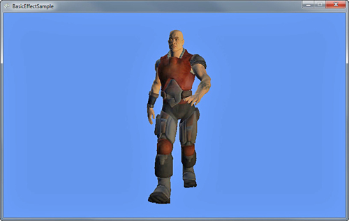
Next, get the list of skin transforms for the current animation, and then loop through each mesh (and each effect on them) to set the bones and the camera information before finally drawing your model. Running the application now is an amazing way to end the chapter; you can see the character walking on the screen (see Figure 6.13).
Figure 6.13. An animated character walking
Summary
This chapter contained a lot of information. You learned about built-in effects in the XNA Game Studio framework and the basics of how these effects work. You can do a wide variety of compelling visual techniques with these effects, and they work on all platforms!
In the next chapter, look at blending, textures and the states of the device.