Chapter 7. States, Blending, and Textures
One of the things you’ve seen only indirectly is how graphics devices’ states and textures interact to form the final output that is rendered to the screen. This chapter delves into this topic more deeply.
Those who are familiar with the previous versions of XNA Game Studio might notice that this is one area where major changes were made. There was a wide variety of reasons, including the fact that it was confusing (and difficult) to ensure the correct values were set, and there were many different options. Although there are still quite a few options available, they’re better organized now and much easier to use and set. In this chapter you will learn about:
• Blend States
• Depth States
• Render Targets
• Sampler States
Device States
In previous versions, there were three main objects used to control the graphics device state: namely the RenderState object, the SamplerState object, and the StateBlock object. As the names implied, the first controlled various rendering states, the second sampler states (textures), and the last was a way to control an entire “block” of states.
The StateBlock objects looked very useful, but in reality, they were a bit confusing to understand, and the performance of them was abysmal. Even when people used them correctly, the performance hit for using them was enough that they would have been better off not using them at all!
Knowing this, the object type was completely removed for Game Studio 4. Various features that relied on this type (such as the SaveStateMode enumeration) were also removed. Don’t worry, though, we made using the states themselves so much easier that you won’t even miss it being gone.
The SamplerState object still exists, although it’s behavior and members have changed. The RenderState object has changed quite drastically. It has mainly split into three new objects: BlendState, RasterizerState, and DepthStencilState. Again, as the name implies, these objects control the blending and rasterization of the scene, along with the depth and stencil buffer options.
Each of these new state objects has a number of properties that they control, and when they are set on the device, all of the properties are set at once. This enables you to easily set a wide variety of states in a single call, where in previous versions the same operation could take quite a few separate calls.
BlendState
One of the most common states you’ll want to change is the BlendState object, which controls how each color in your scene blends with another. At a high level, the blend operation is little more than taking two colors, performing some operation on them, and returning a third blended color. The first color is normally called the source color, and the second color is called the destination color. Knowing this, the actual formula for blending is quite simple:
output = (sourceColor * sourceBlendFactor) blendFunction (destColor * destBlendFactor)
There are several different permutations of this. The following example demonstrates the differences. As they say, pictures are worth a thousand words! Create a new Windows Game project. Add a new item that is a sprite font called Font, and add a piece of content from the accompanying CD, namely alphasprite.png. This is used to easily show the differences in state. Add the following variables to your game class:
SpriteFont font;
Texture2D background;
Texture2D alphaImage;
Texture2D red;
To load and create these as well, add the following to your LoadContent overload:

This example shows the difference between the various blending modes. To do this, you have one background image (that is the destination color) that is the ubiquitous cornflower blue color and one source image (which includes the source color), which is either a solid red color or the data in the alpha sprite. Replace your Draw overload to include the rendering of the background:

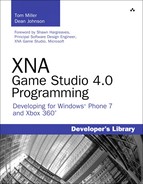
To render your source image easily and compare how it is rendered, add the following method, which helps render the source image with varying blend states:
There are several sprite batch begins and ends in this code, because you need to draw the images differently so you can tell the difference. After you set the blend mode for a sprite batch, it cannot be changed. Because you draw things with (potentially) different blend modes, you need a separate sprite batch Begin/End pair for each.
The first call draws the source image using the built-in BlendState.Opaque object. The built-in objects are described more in depth in a moment, but for now, this object replaces the destination color with the source, ignoring alpha blending. This enables the source image to be rendered without any blending at all. The source image is drawn at the position passed into this helper method.
Next, draw some text describing which blend operation is shown here. Rendering text requires alpha blending to be enabled, so use the default sprite batch Begin call (which uses SpriteSortMode.Deferred and BlendState.AlphaBlend). Also use the MeasureString call on the font so you know how big it is (so you can start the blended image at the correct spot).
Finally, use your last Begin/End pair to draw the image with the specified blending state. During this next section of code, you create state objects on the fly, and every frame. Although this certainly works, it is a bad idea. It creates garbage, and unnecessarily makes your game run slower. In a real game, these are cached and reused.
Warning
You should not create new state objects every frame. This example does it for clarity reasons.
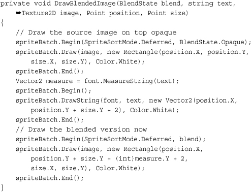
Before you create your new blend object and call the helper function, add two more helper functions to easily calculate the point and size parameters you pass in to DrawBlendedImage:
These simply offset the point by a factor of the size based on the index of the current call. Now add the following code before the base.Draw call in your Draw overload:

Note
After you set a particular state onto the device, it becomes immutable (you can no longer change it). You need to have separate state objects for each permutation you plan on using.
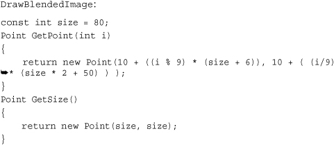
In the previous formula, the blended color for this image is the following:
output = (sourceColor * 1) + (destColor * 1)
Essentially, you add the two colors. Can you predict what it would look like without running the example? If you guessed that it would look like a brighter version of the source red, you’d be correct. Let’s look at why this is using real numbers in the formula. Assume the source color is RGB (Red, Green, Blue) of (255,0,0) and the destination color is (0,0, 255). You have the following:
output = ( (255,0,0) * 1) + ((0,0,255) * 1)
output = (255,0,0) + (0,0,255)
output = (255,0,255)
Pure red added with pure blue gives you a purple color. What if your source and destination colors were the same, and they were each (127,127,127) a mid-gray? Using this formula for the colors gives you the following:
output = ( (127,127,127) * 1) + ((127,127,127) * 1)
output = (127,127,127) + (127,127,127)
output = (254, 254, 254)
This gives you almost a pure white. Adding can be a powerful way to blend. However, what if you wanted to subtract instead? Add this code before your base.Draw call in your Draw overload:

Can you predict what this one will do? This is simply the opposite of the addition, so you should see a dark version of the source image. Using the previous examples, if you use both source and destination colors of (127,127,127), it returns pure black (0,0,0). If you use a source color of purple (255,0,255) and a destination of red (255,0,0), it returns pure blue (0,0,255).
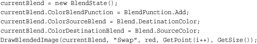
Here’s an interesting one. Add the following code:
currentBlend = new BlendState();
currentBlend.ColorBlendFunction = BlendFunction.ReverseSubtract;
currentBlend.ColorSourceBlend = Blend.One;
currentBlend.ColorDestinationBlend = Blend.One;
DrawBlendedImage(currentBlend, "RSubOne", red, GetPoint(i++), GetSize());
The ReverseSubract value is similar to the Subtract operation except, reversed. At a high level, instead of source-dest, this is dest-source. The formula is the following:
output = (destColor * 1) - (sourceColor * 1)
Knowing this, can you predict what this output color would be? If you guessed it would appear to be a negative of the source image, then bravo for you again! Let’s discuss the last two blend functions. Add the following code:

These two functions are basically self-explanatory. It looks at both pixel colors and picks the largest value if you specified Max, and the smallest value if you specified Min. You see a brighter image for the max function and a darker image for the min function.
Note
The Max and Min values of the BlendFunction enumeration require that both the source and destination use Blend.One.
For each of these examples so far, you used Blend. One for both the source and destination. This is easy to understand because it simply leaves the color unchanged; however, there are quite a few different blend operations available. Blend.Zero is just as easy to understand, because it multiplies the color by zero, effectively ignoring it (depending on the blend function, of course).
To set the blend operation to simply use the source or destination color, add the following code:
Notice that you use the blend operation for the source to be the source color. It doesn’t mean that you are simply using the color as is! Remember the formula, plugging in the data gets you the following:
output = (sourceColor * sourceColor) + (destColor * 0)
Using this essentially doubles the amount of the source in the final color. You can do the same with the following destination:

This makes the following formula:
output = (sourceColor * 0) + (destColor * destColor)
Again, it essentially doubles the destination color. Now, you can also use the inverse of either of these colors by choosing InverseSourceColor or InverseDestinationColor. Calculate the values by subtracting the current color value from the maximum color value for the channel; for example, if you used single byte RGB values such as solid green (0,255,0), inversing this color gives you (255 - 0, 255 - 255, 255 - 0) or a purple color of (255,0,255). Using the inverse of a color on itself cancels itself out, as you can see in the following code:

If you look at the formula, it makes sense (for example, for the first state):
output = (sourceColor * inv(sourceColor)) + (destColor * 1)
output = (destColor * 1)
However, you can just as easily blend with the opposite colors.
This makes the following formula:
output = (sourceColor * destColor) + (destColor * sourceColor)
You can even use the inverse of the colors swapped.

Let’s discuss the last blend operation, BlendFactor (and it also has the InverseBlendFactor to go along with it). This essentially lets you blend either of your colors with an arbitrary color of your choice, for example:

This makes the formula for the output color the following:
output = (sourceColor * 1) + (destColor * blue)
Given the red color of the source image and the slightly blue background color, this color ends up as a bright purple. A common use of a blend factor is to have it change over time to perform fancy effects.
Note
It is unreasonable to force someone to use a new state object for every blend factor (remember that the state objects are immutable). Therefore, use a BlendFactor property on the graphics device to override what is in the state object. Note that the graphics device’s value is updated when the state is applied, so make sure you change it only after the state is set.
There are two more properties to discuss briefly. First are the ColorWriteChannel properties (there are four total) that specify which color channels can be written during the blend operation. Each channel corresponds to a render target, and by default it writes all the channels.
The MultisampleMask property enables you to control which samples are valid for multisampling. By default, all bits are on, so all samples are valid, but you can change this on the fly.
Note
Like BlendFactor, MultisampleMask is also a property on the device so it can be changed without using the blend state.
Premultiplied Alpha
Another change in this release of Game Studio involves the default mechanism used to perform alpha blending. In previous versions, “normal” interpolated blending was performed for alpha blending, which in the formula you’ve been using now was defined as:
output = (sourceColor * sourceAlpha) + (destColor * inv(sourceAlpha))
This was the standard way to declare transparency, but in Game Studio 4.0, the default changed to premultiplied alpha. This mode assumes that the color’s RGB values are multiplied by the alpha value before the blend takes place (hence, the term premultiplied), and the formula for this alpha blending is the following:
output = sourceColor + (destColor * inv(sourceAlpha)
This is similar to the original one, but subtly different enough to matter. Game Studio’s defaults changed to use premultiplied alpha because (while it is not perfect) in the majority of cases, it is the blending mode that most developers actually want in the first place. Plus, it is easy to switch back to the old default way of blending.
What does it mean that Game Studio uses premultiplied alpha as the default? Look at the properties of the AlphaSprite.png that you added to your content project. Under the texture content processor, notice a property for PremultipliedAlpha that is set to true. This means that during build time when the content pipeline is processing this texture, for each pixel that it processes it premultiplies the alpha in this formula:
pixelColor.rgb *= pixelColor.a;
Add the following code to your project to see how the alpha computation changes:
DrawBlendedImage(BlendState.AlphaBlend, "Alpha", alphaImage, GetPoint(i++), GetSize());
If you render this now, the source image has a black background where the alpha channel is when drawn opaque, with a transparent background and the image showing up alpha blended below it. Now, go to the properties of AlphaSprite.Png and change the PremultipliedAlpha value to false. Run the application, and notice that the top and bottom images look the same, and rather than a black background, it has a white background with no alpha blending at all.
I’m sure you can guess why. The blend operation expects the alpha value to be premultiplied, and it is not. The background turned white because without the premultiplication multiplying the 0 alpha value with the white RGB value, returning a 0 RGB value of black, it maintains the white color. However, add the following code to the project:
DrawBlendedImage(BlendState.NonPremultiplied, "NPAlpha",
alphaImage, GetPoint(i++), GetSize());
Because the image isn’t premultiplied anymore, this shows the image normally alpha blended. Lastly, switch the image back to PremultipliedAlpha true. Notice that now both premultiplied and non-premultiplied seem to render alpha blended, and appear to look identical. This is because this particular image only has an alpha value of completely on or completely off. There are no partial alpha values, so the two blend operations come up with the same values. This wouldn’t be the case otherwise.
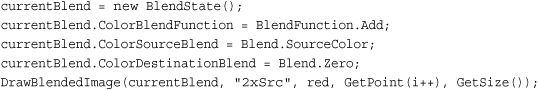
Whew, that was a long discussion about blending. There are a number of built-in blend states for the more commonly used operations as well that are static objects off of the BlendState itself. These include Opaque, Alphablend, Additive, and Nonpremultiplied. After all that, running the app gives you quite a few examples of varying blend modes, much like you see in Figure 7.1.
Figure 7.1. An example of blending states

DepthStencilState
Next up on the list is the depth stencil state. This state has all of the settings and properties required to control the depth and stencil buffers. The previous example is a little dry with just blending the colors, so start a new game project now. Add the depthmodel.fbx model to your content project, and add a few variables to the game, too:
Model model;
Matrix proj;
Matrix view;
Load the model and create the matrices, which you can do in your LoadContent overload:
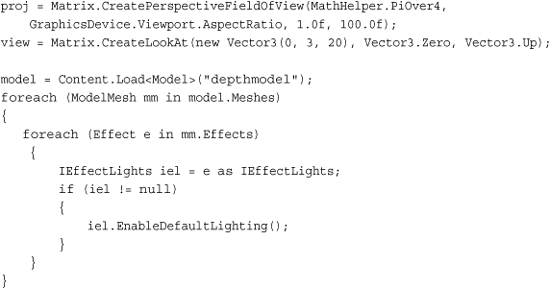
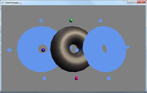
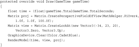
Here, set up a basic camera, load the model, and turn on the lights on the model (because it would look boring and flat otherwise). To draw the model, replace your Draw overload with the following:
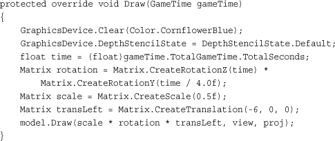
This code renders the model to the left of the screen with it slowly rotating around. Notice that the model is a donut-shaped object with four spheres spinning around with it along its outside border. You also should see that at the beginning of the method, you set the DepthStencilState property on the device, although you just set it to Default. In this particular case, it doesn’t matter if you don’t make this call. When you draw this model again to the right, it will matter.
What exactly is a depth buffer? Well, it’s a buffer to hold depth, of course. If you render a scene with the depth buffer enabled (which is the case by default), for every pixel that is rendered, the depth of that pixel is also stored. You can think of the depth as the distance from the camera. Something near the camera has a depth close to 0.0f, and objects far away have a depth close to 1.0f (the depth runs from 0.0f to 1.0f).
Each time a new pixel is rendered, the system checks whether a depth is written for the position already. If it is, it compares the depth of the current pixel with the one that is already stored, and depending on the function of the depth buffer (which is discussed later), it decides what to do with it. If, for example, the function is CompareFunction.LessEqual, it looks at the current pixel’s depth. If it is less than or equal to the stored pixel’s depth, it writes the new pixel to the buffer; otherwise, it discards it. This enables you to render scenes in 3D, with objects appearing behind (and occluded) by other objects.
To give you an idea of why having the depth buffer is so valuable in a 3D application, add the following code at the end of your Draw overload:
Matrix transRight = Matrix.CreateTranslation(6, 0, 0);
GraphicsDevice.DepthStencilState = DepthStencilState.None;
model.Draw(scale * rotation * transRight, view, proj);
This turns the depth buffer completely off, and then draws the same model again to the right side of the screen, much like you see in Figure 7.2.
Figure 7.2. Rendering a scene with and without depth

Notice that the model on the right looks odd. You can see the small spheres whether they’re in front of the torus or not. You can even see some of the inside of the torus through the other portions of itself. With no depth buffer, the last pixel drawn at a particular depth wins.
In the case of this model, it is composed of five different meshes (the torus, and each sphere is its own mesh). The torus is drawn first, and the spheres next, so the spheres always appear on top of the torus, as they’re drawn later. Depending on how the torus itself is drawn (and which angle it is at), certain pixels in the center of the torus might be drawn after pixels that would normally block it, so you can also get an odd visual with the center.
Before moving on to the specific properties of the DepthStencilState object, let’s take a look at the last static member. You used Default (which turns the depth buffer on) and None (which turns it off). The last one is DepthRead, which reads from the depth buffer, but doesn’t write to it. What does that exactly mean?
It means that it does the same operation as the default depth buffer state—it rejects pixels that don’t pass the depth test, but when it finds a new pixel that does pass the depth test, it doesn’t write the pixel’s depth to the buffer. For example, add the following variable to your game:
Texture2D grey;
Then, create and initialize it in your LoadContent method:
grey = new Texture2D(GraphicsDevice, 1, 1);
grey.SetData<Color>(new Color[] { Color.Gray });
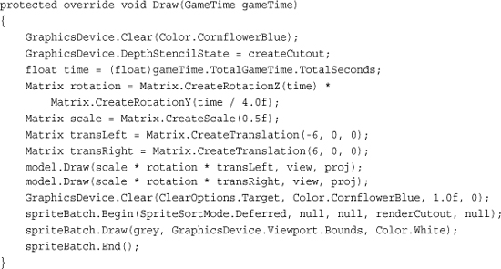
Next, make one change to your current Draw overload, namely deleting the line that sets the graphics device to DepthStencilState.None before adding this code to the end of the method:

Notice that you’re calling a version of Clear that you haven’t seen before. You’re clearing again because you want to erase the two models you just drew, because for this example, they were to write only depth into the depth buffer. However, you cannot use the prototype of Clear that you normally use, because it also clears the depth buffer. So instead, tell Clear to clear only the ClearOptions.Target (the color buffer) to the normal CornflowerBlue, and the rest of the parameters are ignored because they depend on other ClearOptions that you didn’t specify. You can use ClearOptions.DepthBuffer to clear the depth and ClearOptions.Stencil to clear the stencil, with the latter two properties as the values to clear each buffer to respectively.
Draw the model again in the center of the screen (this is where you see the effect of DepthRead in a few moments).
Next, you use one of the more complex spriteBatch.Begin overloads. Aside from the DepthStencilState.Default, the rest of the parameters are the defaults for sprite batches though, so you can ignore those for now. Render the texture to cover the entire screen at a layer depth of 1.0f (the last parameter). Specify the Default depth state because sprite batch (in its default) turns the depth off. Because you turned it on for this sprite, rendering the texture tests its depth (1.0f) against all the pixels in the depth buffer. Any pixels where the models were drawn have a lesser depth, so the pixels in the texture are discarded and not drawn. As you can see in Figure 7.3, this is exactly what happens because you see a gray screen with the outline of the model’s circling there with your extra model floating in between them.
Figure 7.3. Cutouts using depth
Notice that the middle (colored) model looks perfectly normal in the scene. It gets occluded by the cutouts sometimes (when they are behind it), but it shows up in front of the cutouts when it is closer to the camera. This is because it is writing its depth into the depth buffer. Add the following line of code directly after the second Clear call:
GraphicsDevice.DepthStencilState = DepthStencilState.DepthRead;
This is a different output than before. Because it is not writing its depth to the scene, the only places you actually see the rendered model are the portions inside the cutouts where it passed the depth test. So why does this happen?
Let’s trace the lifetime of a pixel through this scene. Imagine the pixel is one in which the colored model is drawn through the cutout and intersecting the left model. First, the scene is cleared; the pixel has the default color and a depth value of 1.0f. Next, the left model is drawn, so now the pixel has the left model color in it, and its depth, you can call it 0.1f to have a nice round number. The right model is drawn next, but it doesn’t affect the pixel, so now the clear call happens again. This time, the color is reset back to default, but the depth isn’t changed, so it’s still 0.1f. Now, the colored model is drawn, it has a depth of 0.09f and passes the pixel test, so the color is now updated, but you aren’t writing depth, so it is still 0.1f. Finally, the grey texture is drawn, and its depth of 1.0f doesn’t pass the depth test, so the colored model’s pixel stays there.
If you are looking at a pixel outside of the cutout, though, something else happens. First, the left and right model don’t intersect the pixel (otherwise, it would be in a cutout), so this pixel is cleared, has a depth of 1.0f, and then cleared again without modifying the depth. Next, the colored model is drawn; it passes the depth test, updates the pixel color, but hasn’t modified the depth, which is still 1.0f. When the sprite comes to render, its value of 1.0f passes the depth test, it overwrites the pixel color with its grey, and you get the scene you see when running this example.
There are only three properties on the DepthStencilState object that deal directly with the depth buffer, and they’re all basically covered by the static members you’ve used already. However, because you aren’t setting them directly, let’s take a look at what they are.
First, you have the DepthBufferEnable property, which enables (or disables) the depth buffer completely. The default value for this is true. You should note that everything in this state object is only meaningful if you actually have a depth buffer. If you don’t need a depth buffer (for example, a purely 2D game with no layered sprites), you can simply turn the depth buffer off for the entire game by changing your PreferredDepthStencilFormat type to DepthFormat.None (the default is DepthFormat.Depth24) in your constructor:
graphics.PreferredDepthStencilFormat = DepthFormat.None;
Next is DepthBufferWriteEnable, which is by default true. This sets whether the system will take pixels that pass the depth test and write them to the depth buffer. You’ve seen the behavior when the write is false in the previous example.
The last depth buffer specific property is DepthBufferFunction, which has a default of CompareFunction.LessEqual. This enables you to dictate how the depth buffer decides whether to allow the pixel or not. By default, the depth buffer is cleared to a value of 1.0f (this is the parameter of the Clear function called depth). Because this is the farthest away point in the depth buffer, anything within the viewing frustum passes the depth test at first. However, you can change this behavior with the various values of the CompareFunction enumeration.
The rest of the properties deal with the stencil portion of the depth buffer, but first, let’s take a bit of time to talk about render targets.
Render Targets
Up until this point, the rendering has been directly onto the screen. You perform a rendering operation, and it appears on the screen. You can go so far as to say that the display was your render target (as in the target of your rendering).
What if you need to render something that you don’t need to show on the screen? You would need a different type of render target, and as luck would have it, there is a RenderTarget2D class available for you!
A RenderTarget2D object is a special kind of texture (it inherits from Texture2D) that enables you to use it as a source for rendering, instead of the device. This enables you to use the render target on your device, and then later, use that rendered scene as a texture. To help visualize this concept, create a new Game project and add the depthmodel.fbx from the downloadable examples to the Content project.
Add the following variables to the project so you can draw the model later and use your render target:
Model model;
RenderTarget2D rt;
Like always, initialize these as well by adding the following code in your LoadContent overload:

Load the model and update the lights as you’ve done many times before. Next is the render target creation. There are three different overloads for creating a render target, with the first as the simplest by taking in the graphics device, the width, and the height. You don’t use this one here because a render target created with this overload does not have an associated depth buffer.
The difference between a render target and a texture is render targets can have associated depth buffers. If you think about it, it seems obvious because it can be a target of your rendering, and rendering 3D scenes without a depth buffer can give you ugly scenes.
The overload for creation used here includes the three parameters, and a Boolean parameter to dictate whether the render target includes mipmaps (which are discussed later this chapter), followed by the color format and depth format for the render target. Notice that this example uses a 256×256 render target. Render targets do not have to be the same size as your display or back buffer. This size was chosen because later in the example, it is rendered overlaid on the screen.
Understanding The RenderTargetUsage Options
The last overload includes the parameter to specify RenderTargetUsage. This enumeration has three values: PreserveContents, PlatformContents, and DiscardContents. The default value for new render targets is DiscardContents, which means whenever a render target is set onto the device its previous contents are destroyed. The framework attempts to help you realize this by clearing the buffer to a solid purple color, a familiar color when working with render targets. If you choose to use PreserveContents, then the data associated with the render target is maintained when you switch to and from the render target. Be warned though, that this can have a significant performance impact because, in many cases, it requires storing the data, and then copying it all back into the render target when you use it again. At a high level, the PlatformContents chooses between the other two depending on the platform, preserving the data on Windows in most cases, and discarding it on Windows Phone and Xbox 360.
Note
The RenderTargetUsage option can be specified for the device as well if you want your device to have preserve semantics.
To show the rendering into the render target, render the model multiple times, and add the following helper method to encapsulate the operation:

This sets up a simple rotating world matrix, turns the depth buffer back to its defaults (you render via the default sprite batch later), and draws the model. This is not fancy, but let’s call it. Replace your Draw overload with the following:
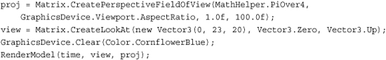
There’s nothing here that’s extremely new and exciting, unless of course you consider the different clear color to be new and exciting. Running the example now shows you the model spinning in the center of the screen. Well, the aspect ratio is different too, because you use this (in a moment) on a render target with a 1.0 aspect ratio (width and height are the same). Now, switch to your render target before you call clear using the following line:
GraphicsDevice.SetRenderTarget(rt);/
Note
You can set up to four render targets at a time for HiDef projects by using the SetRenderTargets method instead.
You probably shouldn’t run the example now, because you’ll just get an exception complaining that you can’t call Present when a render target is set. To unset the render target when you’re done, add the following to the end of your Draw method:
GraphicsDevice.SetRenderTarget(null);
With your rendering now happening onto a separate render target, when you run the example you get a purple screen. As mentioned earlier, this is because your render target (and the device) each have a usage of DiscardContents. When a render target is set with this usage, its contents are cleared to a purple color. In this case, when you set the render target back to null (the device’s back buffer), its contents are cleared and you see purple. Add the following to the end of your Draw method:
Notice that the view matrix has changed so you’re looking at the model from a different direction. However, when you run the example, the model spins in the middle of the scene, and there is only one copy of it. It is as if the first version you rendered vanished, which is somewhat true.
Remember earlier when the RenderTarget2D object was just a special kind of texture? That means you can use it exactly as you would a texture! So, add the following to the end of the Draw method in your example to show both views of the model rendering at the same time:
spriteBatch.Begin();
spriteBatch.Draw(rt, Vector2.Zero, Color.White);
spriteBatch.End();
There it is! Now you can see that the model you drew originally is now in the upper left corner of the screen as in Figure 7.4, and the second model is still spinning in the center. Also, notice that they’re viewed from different angles.
Figure 7.4. Seeing two views from a render target

Note
Just like there is a RenderTarget2D, there is also a RenderTargetCube, which derives from TextureCube.
Faking a Shadow with a Depth Buffer and Render Targets
Why would you want to render something not on the screen? There are quite a few techniques you can use with this type of capability. Let’s take a look at one now, by using what you learned so far in this chapter with the depth buffer and the render targets to fake a shadow on a scene. Create a new game project to get started.
The model you are using so far works well for casting shadows, so add depthmodel.fbx to your content project. For something to render the shadow onto, add dualtextureplane.fbx and ground.jpg to your content project. Open the Content Processor property for dualtextureplane.fbx, and change the Default Effect property to DualTextureEffect, because you will render the shadows as a second texture on the plane. Add the following variables to your game:
Model model;
Matrix proj;
Matrix view;
RenderTarget2D lightmap;
Texture2D lightGray;
Texture2D ground;
Model groundModel;
The render target object is used to store the shadow data (which manifests itself like the light map in the previous chapter). You also need a small texture to form the cutout of your objects, along with the ground texture. You can initialize these in your LoadContent overload:
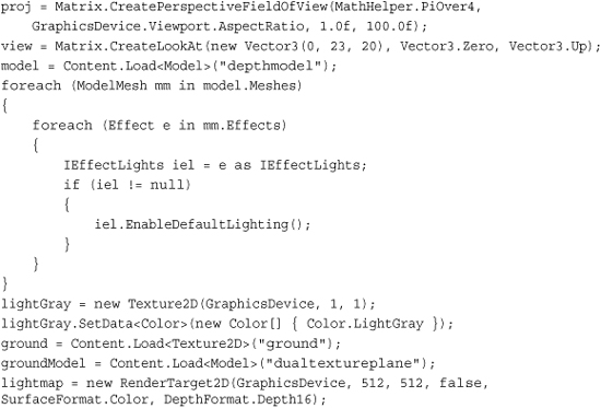
Most of this should look familiar. Note the size of the render target. The smaller the size, the less memory it takes naturally, but you can also get some visual artifacts for having so few pixels to work with. So instead, a medium-sized render target is created. Lower the size from 512 to something much lower (say 64) after the example is complete, and notice how your shadow appears pixelated. Now, because you render the torus models a few times, add the following helper method to your class:

This draw your two models side by side—one to the left and one to the right. Now, let’s take a few different techniques you’ve seen over the last couple chapters and combine them into something awesome. Earlier in this chapter, we discussed using the depth buffer and extra clearing to draw a cutout of an object. This is the basis of your shadows, so you can draw these onto your render target. Replace your Draw method with the following:
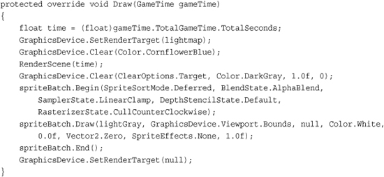
After setting the render target to a custom one, clear the buffer as normal and call your RenderScene helper to draw your two models on the screen. Then, clear the color buffer again (but not the depth buffer) to a dark gray color. This is the color of your cutouts, because right after this you draw your simple sprite across the entire render target. If you remember from your LoadContent method, your sprite texture is a light gray, which means the render target after this is a light gray solid color with a couple of dark gray cutouts of your model.
Remember that a common usage of DualTextureEffect is to render lightmaps onto objects, and your render target now contains essentially just that. Add the following to the end of your Draw method to complete rendering of the scene:
GraphicsDevice.Clear(Color.CornflowerBlue);
RenderScene(time);
foreach (ModelMesh mesh in groundModel.Meshes)
{
foreach (DualTextureEffect de in mesh.Effects)
{
de.Texture = ground;
de.Texture2 = lightmap;
}
}
groundModel.Draw(Matrix.CreateTranslation(0, -20, 0), view, proj);
With everything in place, it’s simply a matter of rendering your scene again, setting the textures on your DualTextureEffect instances on the mesh, and rendering the ground model (that uses those textures) slightly lower in the scene. Your objects now have real-time shadow’s as in Figure 7.5.
Figure 7.5. Using the depth buffer to form shadows

Back to Device States
Along with the depth buffer, you can also have a portion of that reserved for the stencil buffer. This is similar to the depth buffer in that it is evaluated on a per pixel basis, using a series of tests. Let’s look at emulating the cutout you did earlier, but by using the stencil buffer instead.
The Stencil Buffer
Create a new Game project and add the depthmodel.fbx to your Content project. Then, add the following variables to your project:
Model model;
Matrix proj;
Matrix view;
Texture2D grey;
DepthStencilState createCutout;
DepthStencilState renderCutout;
The last two are the states you use for the stencil buffer—the first to create the cutout, and the second to use the cutout to render. However, by default, your application doesn’t even have a stencil buffer; it has only a depth buffer. Go to your game’s constructor and add the following line to the end:
graphics.PreferredDepthStencilFormat = DepthFormat.Depth24Stencil8;
This tells the runtime that you prefer a depth buffer that includes eight bits reserved for the stencil buffer. This is actually the only stencil buffer available in the XNA runtime. With that, instantiate your variables in the LoadContent overload:

You should recognize the earlier portion of the snippet, but notice something new after creating the two DepthStencilState objects. Before looking at the drawing code (which is quite simple), let’s take a look at what these properties are actually doing.
Unlike the depth buffer, the stencil buffer is slightly more complicated than a simple comparison of two values (although, in many cases, it is the same). The basic formula for computing a stencil value is the following:
(ReferenceStencil & StencilMask) Function (StencilBufferValue & StencilMask)
If your mask value is always all bits, then this is a comparison of the reference value to the buffer value. As you see previously, you use the ReferenceStencil property to dictate what the value is. You have the same compare functions that you had with depth buffers, but you have a completely new set of operations you can do if the stencil has passed, found in the StencilOperation enumeration. You can use Replace, to put the reference value into the buffer, and you can use Zero, to put a value of zero in the buffer. You can choose to Keep the current buffer value as it is (the default value of the operation). You can choose to Invert the value in the buffer, or you can Increment or Decrement it. The saturate versions of these methods simply clamp the value at the maximum or zero, respectively.
By default, the stencil buffer is turned off, and cleared to a value of zero. So, in order to create the cutout, first turn on the stencil buffer. Then, change the CompareFunction to Always. This means for every pixel that is drawn, you perform the operation in the StencilPass property, which you choose as Replace. This replaces the buffer value with the ReferenceStencil value, which you’ve placed as one now.
This means that when you render the models later, using this depth state, the stencil buffer initially is completely zeros, but for every pixel it renders, that pixel’s stencil buffer value is updated to one. Next, look at the state you use to render the cutouts.
Again turn on stenciling, but this time set the compare function to Equal. Because your ReferenceStencil value is zero, any pixel with a stencil value other than zero will fail, and not be drawn. If the stencil value is zero, you keep the value because you specified the Keep operation. This means that when you render the second overlay sprite, it does not render the pixels where the model used to be because they have a stencil value of one. Every other pixel has a stencil value of zero.
Now that you have a basic understanding of the stencil buffer and its operation, replace your Draw overload with the following:
With that, you now render cutouts of your models using the stencil buffer as in Figure 7.6. It is trivial to update the example you used previously for shadows to mirror this functionality using the stencil buffer.
Figure 7.6. Using the stencil buffer to form cutouts

RasterizerState
As you learned in Chapter 4, “Introduction to 3D Graphics,” rasterization is where the graphics device converts the triangles into pixels. The RasterizerState object enables you to have a measure of control over this process in a variety of ways. To see the kinds of controls you have, create a new Game project and add the depthmodel.fbx file to your Content project. Then, declare your instance variables for the game:
Model model;
Matrix proj;
Matrix view;
RasterizerState wireframe;
RasterizerState scissor;
The RasterizerState class has a few static members that you can use, but you also use two extra states in this example. Create the following objects in your LoadContent method:
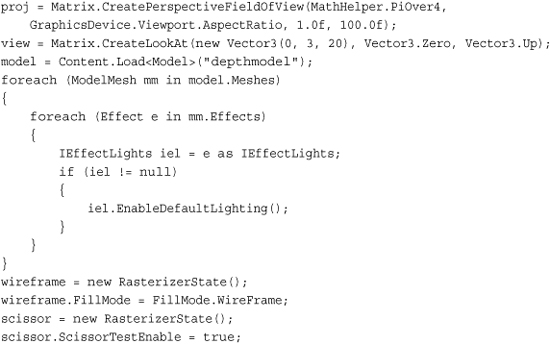
After the matrices and the model are created and the lighting initialized, create your two needed state objects. The first changes the fill mode to WireFrame. The only other option for this property is Solid, which is the default. When you’re rending an object with WireFrame enabled, you see only the triangles rendered, but not the pixels inside of them. For the next option, turn on the ScissorTestEnable (the default is false). This is discussed in a moment when you see what it does! Now replace your Draw method with the following:
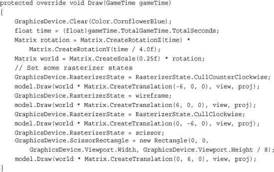
Here, you draw the model four different times, each time with a different rasterization setting and in a different location. The first draw call uses the static RasterizerState.CullCounterClockwise member, which sets the CullMode property of the state to CullCounterClockwise. This also happens to be the default, so this first object appears exactly as it normally would if you hadn’t set this state. So what exactly does CullMode mean, and what does it do?
When the device renders a triangle, it has two sides, but for most 3D models, you can see only one side of a given triangle. So each triangle has a “front” face, the side you expect to see, and a “back” face, the side you probably won’t see. The CullMode property tells the device to rasterize only pixels for one of those faces. This is determined by the vertices of the triangles “winding order.” Triangles have either a winding order of clockwise, or counterclockwise. CullCounterClockwise tells the device to cull (remove) faces with a winding order of counterclockwise. The default winding order for XNA applications is that the front-facing triangles are wound clockwise and back-facing triangles are wound-counterclockwise.
Next, draw the model to the right with the wireframe state. As you expect, the model is not drawn solid, but instead with the triangles being drawn, but not the pixels inside of it. This mode is called wireframe.
The bottom model is drawn with the opposite culling mode. While running the application, notice that it looks odd. This is because it’s rendering only the “wrong side” of each triangle, so you see what the model looks like almost inside out. You can also use the built-in static member RasterizerState.CullNone to render both sides of each triangle.
The last model (the one drawn at the top of the screen) simply turns on the scissor test. The scissor test tells the device to not render any pixels that are outside the ScissorRectangle property of the device (which by default is the same size as the currently applied render target or back buffer). In this example, you set the rectangle to be the entire width of the screen, but only the upper eighth portion, which causes the model to be cut in half. Why are the other three models still showing despite the fact you told the device to render only in the upper eighth of the screen? The other three models were rendered with a state that had the scissor test turned off.
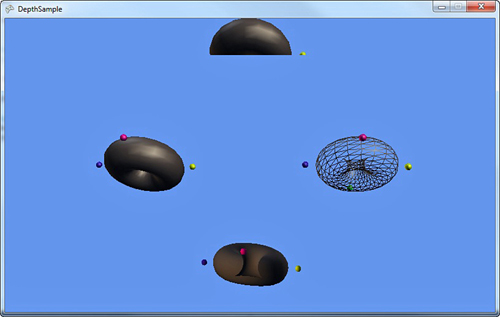
When you run the example, you see each of the four rasterizer states, as shown in Figure 7.7.
Figure 7.7. Various rasterizer settings
SamplerStates
The last of the device states we discuss is the sampler state. This state controls how the textures that are rendered by the system are handled. Why is it called a sampler state rather than a texture state? These settings are used when the texture is actually sampled to get a particular color, rather than the state of the texture itself.
The majority of pre-created static members of the object have to do with texture addressing. Normally, texture coordinates go from the range of 0 to 1, but what if yours go beyond that? The texture addressing mode determines how the texture is sampled from outside this range, so let’s take a look at a quick example. Begin by creating a new Game project and adding a texture to the Content project (for example, cat.jpg). Declare a variable to hold your texture and one of your states as well:
Texture2D texture;
SamplerState linearMirror;
Initialize the following variables in your LoadContent method as normal:
texture = Content.Load<Texture2D>("cat");
linearMirror = new SamplerState();
linearMirror.AddressU = TextureAddressMode.Mirror;
linearMirror.AddressV = TextureAddressMode.Mirror;
linearMirror.AddressW = TextureAddressMode.Mirror;
linearMirror.Filter = TextureFilter.Linear;
Before we go on, let’s take a look at the state you just created. As you can tell, you can set the address mode on any of the components of the texture coordinates separately (U,V, or W), although, in most cases, you simply set them all to the same thing as you did here. We discuss what each of the three valid address modes are in a moment after you see the other two. Replace the Draw overload with the following and run the application:

At the beginning of this method, you first pick which sampler state you will use, using a quick formula to change it every second between one of three different states. The first is LinearClamp, which is just like the one you created previously, except Mirror replaced with Clamp as the addressing mode. Next is LinearWrap, which again, uses the Wrap addressing mode. The final one is the mirror mode you created earlier. What do each of these do? You can probably tell partially just by running the example, which rotates through them as in Figure 7.8.
Figure 7.8. The Wrap texture addressing mode

The first mode is Clamp. This “clamps” your texture coordinates between 0 and 1. It does this by artificially stretching the border pixels for the texture infinitely. This is why when you see the cat rendering from the beginning, it looks like it is smeared into position where you can bands to the left and right, as well from the top and bottom of the texture.
Wrap, which you see during the running example (and can somewhat tell from the name), simply wraps the texture indefinitely in all directions. A UV coordinate of 1.5,1.5 is read the same as a UV coordinate of 0.5,0.5.
The last mode is the Mirror mode, which is similar to Wrap in that it repeats the image indefinitely, but each new image required is flipped from the previous one. Notice that the flipping happens on both the horizontal and vertical axis as well.
You might wonder how this image was rendered with a set of texture coordinates outside of the 0,1 range. After all, you expect that using sprite batch renders only the texture you passed in, and for the majority of cases, this is very true. However, look at the third parameter to the sprite batch Draw method here. You use a source rectangle that goes beyond the bounds of the texture. The sprite batch detects this and maps the UV coordinates across the range of the source rectangle, where the ranges from 0–1 are the coordinates within the actual source of the texture, and everything else is not.
The last parameter is the Filter of the sampler, which dictates how the sample color is determined if it isn’t exactly a single pixel (for example, it is between two pixels). The XNA Game Studio runtime supports three different filters: Linear, Point, and Anisotropic. Notice a few other permutations in the list of possible values with various combinations of “min” (standing for minify, the act of shrinking a texture), “mag” (standing for magnify, when a texture is enlarged), and “mip” (standing for the mip levels, when you have a texture with a set of mip maps). For example, the MinLinearMagPointMipLinear value means it uses linear filtering during minify, point filter during magnify, and linear filter during mipmapping.
What Is Mipmapping?
At a high level, mipmaps are a collection of images representing a single texture at various depths. Each image is half the size of the one before it. For example, if you have a starting image that is 256×256 pixels, it has a series of eight different additional images for different depths (or mip levels), of sizes 128×128, 64×64, 32×32, 16×16, 8×8, 4×4, 2×2, and 1×1.
If your texture has mipmaps, the runtime picks the appropriate sized image based on the distance from the camera. Items extremely close to the camera use the higher resolution images, and items far from the camera use the low resolution images. Normally, mipmaps are generated by filtering the next higher resolution down. However, there’s nothing stopping you from having your artist give you the entire mipmap chain and using it directly.
Although you can get a boost in image quality by using mipmaps, one of the major disadvantages is memory consumption. Because you store multiple different copies of the image at different resolutions, you use at least double the memory.
Other Texture Types
Although you’ve been using mostly Texture2D and similar objects, there are actually two other types of textures available in the system as well. These are the TextureCube and Texture3D classes.
A cube texture (like the name implies) is a texture that includes six sides, such as in a cube (refer to Chapter 6, “Built-In Shader Effects”). A common usage of this texture type for the environment map effect is to render portions of the scene six times (one for each face of the cube) into a cube render target and then use it as your environment map.
Summary
Unlike previous versions of Game Studio, you are encouraged to update your state whenever you draw something new. Setting state is cheap and easy, and now you have the basics for how to use the various permutations available to you. If you ever want to get the device back to its default state, you can do it in four easy lines:
GraphicsDevice.BlendState = BlendState.Opaque;
GraphicsDevice.DepthStencilState = DepthStencilState.Default;
GraphicsDevice.RasterizerState = RasterizerState.CullCounterClockwise;
GraphicsDevice.SamplerStates[0] = SamplerState.LinearWrap;
In the next chapter, you delve into the world of custom effects, where you write effects to do amazing things.