
PROJECT 1
Desoldering Basics
IN ORDER TO Build an electronic circuit from plans or from scratch, you will need a number of semiconductors and components. Often, these individual components cost only pennies now, but in order to purchase from a large supplier a minimum order number or price level has to be met. It seems crazy to pay $25 in shipping to receive a few 10-cent capacitors or resistors, especially when you can salvage them from just about any old circuit board. Almost all of the components we use are salvaged from old boards. We never had to order an odd value resistor or capacitor as we have always found what we needed by scavenging our huge junk piles.
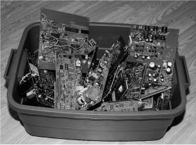
Figure 1-0 Most of your parts inventory can be salvaged from old circuit boards.
A few dead TV or VCR circuit boards will net you enough raw components to fill an entire electronics parts bin and allow you to experiment with varying values as you breadboard a new or published circuit from a schematic. Almost any discarded appliance that includes a power cord will become a great source of raw semiconductors, so tell everyone you know not to throw out their broken appliances and instead send them to your mad scientist lab for dissection!
A decent soldering iron will make your work so much easier, allowing the heat to be adjusted to the job at hand. Sure, you could do a lot with a ten-dollar soldering gun, but when it comes to removing components or soldering small pin devices, the budget soldering iron may not be of much use. A fine point and a lot of heat will make component extraction very easy, especially on multilayered boards, which require the heat to reach the inner copper layers in order to melt the solder. A soldering station with a heat control and interchangeable tips is one of those must-have items if you plan to invest any time in the electronics hobby (Figure 1-1). A decent soldering station can be purchased at most electronics suppliers, and will range in price from $50 to $200, depending on what features and accessories are included. If your soldering system does not include a sponge bath, then just wet an ordinary kitchen sponge with some water, as this will be needed in order to clean off the tip as it gums up with flux and old solder.
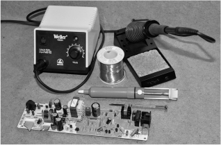
Figure 1-1 The basic tools you will require for any soldering or unsoldering work.
Large through-hole semiconductors can often be ripped up from old circuit boards using a soldering iron and your fingers to lift the parts, but there will be limits to this technique, especially on smaller components or those with more than two or three pins. A desoldering tool, often called a “solder sucker” is essential for removing short-lead semiconductors, as well as those with multiple leads, such as integrated circuits (ICs). This simple tool contains a spring-loaded plunger that basically sucks up the heated solder, clearing the area around the lead and hole so that the part can be removed from the board. On most boards, it is possible to cleanly lift up a 40-pin IC in a few minutes so that it can be reused or even placed into a solderless breadboard. A solder sucker is also good for removing large components that have been placed down with a lot of solder to secure them to the board or transfer heat.
You will also require a spool of solder, even when unsoldering components, as there will be times when you have to melt a bit of solder into a hole in order to use the solder sucker to clean up the hole. Molten solder is a liquid, so the transfer of heat between the newly added solder and the hard-to-reach solder stuck in the center of a multilayer board will allow the solder sucker to pull up every bit in one shot. For electronics work, you will need flux core (rosin core) solder, which is a thin, hollow solder with special antioxidizing chemicals in the center that clean and protect the copper when soldering. There are various diameters of solder, with 0.032 inch being a good choice for all-around electronics work. The type of solid heavy solder used for plumbing is of no use for electronics work!
If your soldering system includes a dial to set the heat (amperage), then this will come in handy when working with the larger through-hole components and board-mounted hardware, such as switches, heat sinks, connectors, and large-pin devices. You don’t have to worry too much about damaging a component with a soldering iron, as it has been designed to withstand a lot more heat during the manufacturing process than you will be subjecting it to here. When we unsolder, we always crank up the station to the highest setting, as this releases the part faster, subjecting it to less time under the gun (Figure 1-2).
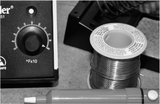
Figure 1-2 A higher heat setting is best for unsoldering larger components.
Once you become proficient at arming, aiming, and snapping the desoldering tool, you will be able to lift a 40-pin IC from a circuit board in about 60 seconds flat. This tool will allow you to cleanly rip up just about any component from a board in such a way that the pins look almost brand new again, ready to be inserted into a solderless breadboard. It does take some practice to get the rhythm down though, and there is a split-second where the solder sucker must be positioned right over the pin just as the solder pools in order to completely evacuate a hole (Figure 1-3). If you are too slow or fail to aim the top over the hole, you will only pull up part of the solder; this will require you to actually use new solder to fill the hole back in again so you can try a second time. Proficiency will come with practice, and after your tenth TV circuit board, you will be able to wield the soldering gun and desoldering tool with Jedi reflexes. Oh, but your thumb muscles will ache for a while as you get used to pressing down that button.
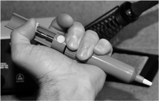
Figure 1-3 Get used to arming and aiming the solder sucker with accuracy.
Like all products, the desoldering tool will range in quality depending on the manufacturer and price, and it is worth investing in one that will last for some time. Each time you evacuate a hole, the molten solder will solidify in the tube and will drop back out on the next press of the plunger. Of course, a small amount of solder will stick to the internal spring or casing, eventually clogging the device. To clean the solder sucker, unscrew the two halves and then clean the debris out as much as you can, ensuring the small rubber ring is also clean. A bit of vegetable oil can be used to lubricate the unit for continued efficiency. This cleaning process should be done after a full day of use or when the loading system seems to stick (Figure 1-4).

Figure 1-4 The desoldering tool will need to be cleaned every so often.
Although the current trend is to reduce the size and number of components on a printed circuit board to reduce cost, there will always be something to salvage, and older boards will be a regular gold mine of usable parts. Large capacitors, resistors, transistors, light-emitting diodes (LEDs), diodes, and any other two- or three-pin through-hole component can easily be removed using only your fingers and a soldering iron by simply heating and lifting them free (Figure 1-5). If the component is small enough that you can heat all of the pads at the same time, then the process is very simple—just heat and remove. Larger devices require a bit of working to release them from the circuit board.
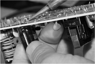
Figure 1-5 Larger components with two or three pins are easy to remove from a board.
Heat one of the pads as you rock the component to one side in order to slide the lead out of the hole as much as you can before the part hits the one next to it. If the device has more than two pins, then you can’t bend it as far, as you may bend one of the other pins. Transistors and other large devices need to be worked out a small bit at a time, heating each pad one at a time.
Once you have melted the solder on one of the pads, bend the component as far as you can before it hits the one next to it, and then withdraw the heat to let the lead settle back in the hole. The process is then repeated on the other lead, working the component out of the board a bit at a time (Figures 1-6 and 1-7).
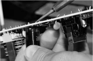
Figure 1-6 Slide the lead out of the hole a bit at a time and then let the solder cool.
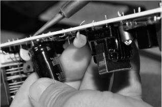
Figure 1-7 Keep working each lead until the component is freed from the board.
When you are working a component off the board using the heat and rock technique, be careful not to bend the leads so far that they break right off. Some capacitors have such short leads that there is no space between the underside and the board, so too much movement may rip the lead right out of the casing. Also, some devices, such as large resistors, transmit heat to their outer bodies, so you will need to work fast or use tweezers with this technique in order to avoid burning your fingers.
This lead rocking process only takes a few seconds if you have your soldering iron set on high, and will not damage the part if done carefully (Figure 1-8). Some cleanup of the leads might be necessary after, though, as the molten solder may stick to the lead as you release the component from the board. This lead cleanup is only necessary if you plan to place the part in a solderless breadboard, as the solder blob may be too wide for the slot on the breadboard.

Figure 1-8 After heating the pads several times, the part is finally released.
Some devices are inserted into a circuit board with very short leads or in such a way that makes it impossible to manipulate the part with your fingers (Figures 1-9 and 1-10). Resistors that are laid down horizontally are often difficult to lift up by hand as there is not much to hold on to, and they become extremely hot in a hurry. If you can get a hold of the device and pull it quickly, you may be able to lift it by hand, but after a while, your fingers will start to develop heat blisters. Resistors and diodes can be pulled up from a board by heating the lead while you pry them up with tweezers or a small screwdriver blade. Actually, you only need to pry up one end and then you can easily pull the component from the board by melting the pad on the other lead and pulling it away from the hole.
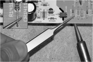
Figure 1-9 Smaller components with short leads can be heated and pried up.

Figure 1-10 Delicate components need to be removed carefully.
When there is no way to safely grip or pry up a component, you will need to evacuate the hole by using the desoldering tool in order to remove the part. If the lead has been bent outwards during the manufacturing process, try to straighten it as much as you can so that the solder sucker can pull out the solder evenly around the lead and the hole. Many ICs and components are inserted by a machine that forces the pins to fall against the edge of the holes. This can make solder evacuation more difficult.
Depending on the amount of solder and size of the pad, you may need to make multiple strikes with the desoldering tool in order to free the part (Figure 1-11). Heat up the pad until the color of the solder changes (molten solder becomes very shiny), and then quickly place the loaded solder-sucker tip right over the pin and press the release button. If you managed to make a seal between the work and the tip while the solder was still molten, then most of the hole will be cleared out. Larger pads will require a few attempts to clear out all of the solder (Figure 1-12).

Figure 1-11 Timing and aim are the key to using the desoldering tool.

Figure 1-12 Sometimes the lead will be stuck to the side of the hole.
On larger devices with thick leads, the solder sucker may not evacuate the entire hole, leaving a small connection between the edge of the solder pad and the lead. Often, you can just grip the lead with pliers or tweezers to move it away from the edge of the hole (Figure 1-13). This is the reason that leads should be a straight as possible before using the desoldering tool. On smaller components, a quick push with your fingernail will easily release the lead from the edge of the hole. If you cannot free the lead, then it may be necessary to fill the hole with fresh solder and then use the desoldering tool again.

Figure 1-13 Once one lead has been freed, the fuse can be pulled from the board.
The fuse shown in Figure 1-13 couldn’t be pried up until one end was already removed from the board as the glass was too smooth to get a grip on, and any prying might have broken the glass. Large ceramic resistors are also similar and made of very fragile material that cannot by pried easily.
To prepare a part for reinsertion into a board, use the desoldering tool to remove any solder blobs from the leads and then press them with flat pliers to straighten the leads (Figures 1-14 and 1-15). This becomes important if you plan to install larger pin devices into a solderless breadboard as there is a limit to how large a pin will fit before causing stress on the internal plates that connect the rows.

Figure 1-14 Leads are cleaned and straightened after removing a part.

Figure 1-15 Clean the leads with the desoldering tool after removal.
When cleaning up the leftover solder from a larger part like a capacitor, be careful not to overheat the leads as it may be possible to damage the internals now that there are no copper solder pads to help dissipate the heat. Only heat up the part as much as necessary in order to melt the solder for extraction. Another trick that can be used to remove solder blobs from the pin is the heat-and-shake method, which involves melting the solder and then flicking the part to send the molten solder flying off. Do this into a garbage pail or onto a surface that will not be tarnished by the molten solder.
On larger pin devices, a twisting motion with ridged pliers can also help straighten up and remove leftover solder from the leads. Since the solder is much softer than the lead, it can be removed by the grinding action of the pliers. Only use enough pressure to remove the solder without bending or twisting the lead (Figure 1-16).
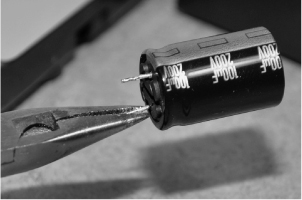
Figure 1-16 A twisting motion can also remove the excess solder.
For use in a solderless breadboard, leads should be cut to a length of no more than half an inch. It is also important that leads be straightened and positioned so that they fit into the holes without stressing the part. For use on a perforated board, it may be best to keep leads as long as possible as they could be used to help form solder points and traces on the underside of the board. Trim both leads to an equal length for breadboarding (Figure 1-17).
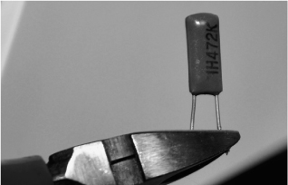
Figure 1-17 Trim both leads to an equal length for breadboarding.
When you are first building up your semiconductor inventory, there are obvious common values that you will need with capacitors, resistors, transistors, and logic ICs (Figure 1-18). You will find more than enough common components on just about any salvage board such as 1-, 10-, and 100-μF capacitors, 1-, 10-, and 10-K resistors, and small NPN signal transistors. As you build projects from plans and schematics, common values will become obvious, and even resistor color codes will become easily recognizable right away. These common values will be the starting point for building a well-organized inventory that will probably end up spanning several multidrawer component bins.
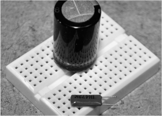
Figure 1-18 A pair of solderless breadboard compatible salvaged capacitors.
As you desolder and solder, the tip will need constant cleaning to allow for a proper transfer of heat to the work (Figure 1-19). The wet sponge is used to clean the tip by dragging it across the surface to remove the old solder buildup. Do not let your soldering iron sit in the holster while a blob of old solder is stuck to the end as this will slowly degrade and pit the tip, making it eventually break or deform. Before putting your soldering iron down, wipe the tip first.
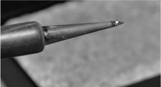
Figure 1-19 Old solder will build up on the tip of the soldering iron as it is used.
Most soldering stations will include a holster and a sponge, but if you only have a basic system, any kitchen or bath sponge will work. Just wet the sponge until it is saturated (but not dripping) and then it will be good for a few days. To clean the solder blobs from the tip, drag the hot soldering iron across the sponge and spin it as you go (Figure 1-20). The solder blobs will be stuck on the surface of the sponge and when it finally dries, they can be shaken off into a garbage can. Remember to always clean the tip when you are going to shut off or holster the iron for any amount of time to avoid ruining the fine point in the tip.
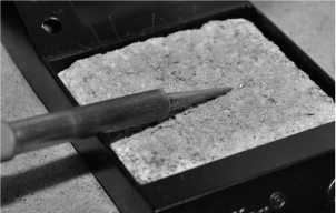
Figure 1-20 Drag the tip with a turning motion to clean off the old solder blobs.
The clean soldering iron tip will have a difficult time melting a large blob of solder unless it has a bit of solder on it already to help transfer the heat to the target. This wetting of the tip or “tinning” is important when you are soldering large pads or bare copper pads and new leads (Figure 1-21). To tin the tip, just melt a small amount of new solder to the tip and then run it across the sponge to get rid of any excess solder. This process places a small coating of solder on the tip, which allows the transfer of heat to the work. As you solder, this difference will become obvious.

Figure 1-21 Tinning the tip will help the transfer of heat to the work.
Surface-mounted devices (SMDs) can be quite a task to solder by hand because of the fact that the capillary action of the molten solder is enough to trap them or make them stick to the tip (Figure 1-22). To work with surface mounted semiconductors, you will definitely need a good set of tweezers, a magnifier, and a steady hand. SMD work is not all that bad once you get past the pitfalls, and desoldering components can be done with a sharp tip and a pair of good tweezers. The desoldering tool is almost useless for SMD work as the parts are so small they will end up lost inside the vacuum chamber or broken by the force.

Figure 1-22 Surface-mounted components add a level of difficulty to soldering.
SMD components are so small that even static electricity can cause havoc as you handle them. There are also different types of marking and coding used because of the small amount of space available, so you will need to learn another facet to this hobby when working with SMDs (Figure 1-23). Oh, and don’t bother looking around on the floor if you drop one of these parts...the chance of recovering one is not worth the effort!
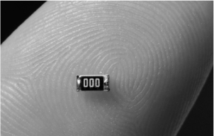
Figure 1-23 A surface-mounted resistor is smaller than a grain of rice.
Surface-mounted ICs have many sizes of packages and pins, and many are well within the realm of hand soldering, so don’t be afraid to try to save these parts from a circuit board. Many of the common logic ICs or op amps have few enough pins that they can be easily lifted from a board using only a small screwdriver and a soldering iron (Figure 1-24). There are specialty tools available for SMD work, but a lot can be done with just the basic tools as well.

Figure 1-24 Lifting a surface-mounted IC using the pry method.
One easy method of lifting a surface-mounted IC is to gently pry up on one end as you drag the hot soldering iron tip back and forth across the leads on that side. You will need to tin the tip and slide it back and forth in order to evenly heat all of the pins at once so that end will lift form the pads. Don’t pry too hard or push too much on the part or it will be damaged (Figure 1-25). When the pins on one side become free from the pads, you will hear a snap sound and the part will be lifted slightly on that side.
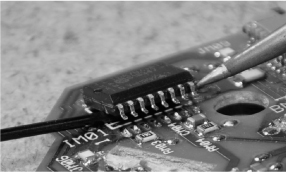
Figure 1-25 One side of the surface-mounted IC has lifted from the pads.
Once the side you are working on has popped from the board, stop prying so the pins on the other side don’t become bent or broken. The heating and sliding process can then be done on the other side using tweezers or your fingers to lift the IC completely from the board (Figure 1-26).
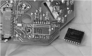
Figure 1-26 Another successful surfacemounted IC extraction.
Once the surface-mounted IC has been fully removed from the pads, straighten and clean any pins that have been bent or may still have solder balls or bridges on them. This method of extracting IC packages works well for most ICs that have pins on both sides. For ICs that have pins on all four sides, this method will probably be of no use, and will require a heat gun to be used to evenly heat the entire part.
We used to spend hours unsoldering components from boards, throwing them all in a huge bin for later sorting, but found this to be a huge process (Figure 1-27). Looking up datasheets and cross-referencing all of these parts took a lot longer than the removal process. Instead, now we go hunting for certain parts, like a 0.01-μF disc capacitor and sort them in groups as they are extracted. Having a massive tangle of resistors is completely useless when you need to find a specific value, so sorting after extraction is important. Sometimes we just leave resistors on the boards, as it would be impossible to sort all but the most common values into groups. ICs, capacitors, transistors, and larger components are usually easy to sort, so they are done as they are extracted.
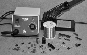
Figure 1-27 Sorting and organizing a huge inventory can take some time
We have 10 or more large parts cabinets completely full of salvaged semiconductors, all sorted by value, type, or use (Figure 1-28). Although 90 percent of the inventory came from free scrap boards, there must be thousands of dollars in usable components in there now. Every resistor costs something if you have to order it from a supplier, so don’t pass up any scrap boards for salvage. Tell your friends and family that all nonfunctioning and functioning appliances are welcome in your lab for dissection, and build up that junk pile as much as you can!
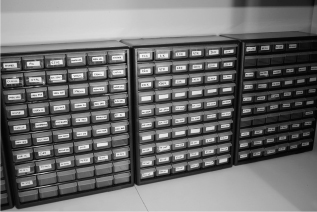
Figure 1-28 Parts cabinets with small drawers are perfect for staying organized.