
PROJECT 20
Portable Alarm System
THIS PROJECT DETAILS a simple yet effective security system that is perfect for temporarily protecting an area or building. This portable alarm system functions much the same way as a typical hard-wired home security system, allowing for a timed entry and deactivation via numerical keypad. The alarm system will respond to practically any type of sensor input such as a motion switch, magnetic door switch, window break tape, infrared motions sensor, and any other sensor that acts like a simple switch. Because the main unit contains all of the electronics, alarm, keypad, and battery, the alarm trigger sensor can be remotely located, making it difficult to disarm the system once it has been activated by an intruder.
![]() IC1: ATMEL ATMega88P or similar microcontroller
IC1: ATMEL ATMega88P or similar microcontroller
![]() Keypad: Sparkfun 12 button keypad or similar
Keypad: Sparkfun 12 button keypad or similar
![]() Resistors: R1 = 10 K, R2 = 1 K, R3 = 1 K
Resistors: R1 = 10 K, R2 = 1 K, R3 = 1 K
![]() Transistors: Q1 = 2N3904 or 2N2222A NPN
Transistors: Q1 = 2N3904 or 2N2222A NPN
![]() LEDs: LED 1 = red LED, LED 2 = green LED
LEDs: LED 1 = red LED, LED 2 = green LED
![]() Diodes: D1 = 1N4001 or similar
Diodes: D1 = 1N4001 or similar
![]() Relay: Any small 3- to 5-V relay
Relay: Any small 3- to 5-V relay
![]() Buzzer: Small 2 wire piezo element
Buzzer: Small 2 wire piezo element
![]() Alarm: Battery operated pocket alarm
Alarm: Battery operated pocket alarm
![]() Battery: 3- to 9-V battery or pack
Battery: 3- to 9-V battery or pack

Figure 20-0 This security system works as both a permanent or portable alarm.
The goal of this project is to demonstrate how to connect a keypad matrix to a microcontroller to scan the rows and columns for key presses and to create a simple security system that can be used as the framework to create your own security system, leaving a lot of room for modifications and improvements. Practically any type of matrix keypad can be used, and the alarm siren used is a common and inexpensive pocket alarm that has been modified to allow switching through a relay. The microcontroller used is an 8-bit ATMega88, but just about any microcontroller can be used, as only a few IO pins are needed. The programming is done in C for portability and clarity.
The alarm is activated or deactivated by entering a secret code on a 12-digit keypad like the one shown in Figure 20-1. This keypad is from SparkFun.com, part number COM-08653, but any keypad will work as long as you know the pinout. You could even make this alarm system with no keypad at all and just use the microcontroller as a simple time delay to allow arming and disarming the system, using the power switch to turn the alarm on or off.

Figure 20-1 Most keypads are wired as a matrix of rows and columns.
Unlike a permanent home security system where the keypad is right at the door and the alarm is hidden, this system places the keypad and alarm in the same box, so the goal is to locate it deep inside a building and run a wire to the actual trigger sensor. In portable mode, the sensor can be affixed to the alarm box, allowing it to be propped up against a door or placed in a drawer or even a suitcase. Having the alarm, battery, and main electronics located in the same box means that this particular alarm system design is probably not the best solution for a permanent installation, but it does work very well as a portable system or when you just need temporary security for a building.
Although it may look confusing at first glance, the wiring diagram shown in Figure 20-2 is commonly referred to as a “matrix,” as the button switches are made of common row-and-column connections. It certainly takes a little more work to decode a single button press into a microcontroller on a matrix system, but if each key had its own wire, then this 12 button keypad would need 12 input/output (IO) lines on the microcontroller. Using a matrix, the keypad now only requires 7 IO lines, a significant savings.
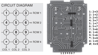
Figure 20-2 Arming and disarming the alarm is done by entering a code on a keypad.
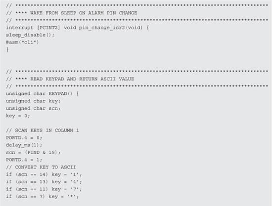
In a matrix-connected keypad, there is no common ground to all button switches since they all share a row or column. To decode a matrix keypad, you have to turn on a single column at a time and then scan the rows for the current button press. By doing this, you basically turn the keypad into a commonly-connected row of switches momentarily. This may seem like a lot of work, but it happens in a few microseconds in the microcontroller with just a few lines of program code as will be seen later.
The SparkFun keypad has a rounded rectangular shape, so mounting it into a box will require some fancy cutting to make a snug fit. There are several methods that can be used to mount this keypad in a box: cut the exact rounded rectangular shape as we are going to do, cut a smaller 90 degree rectangle so that only the keys are visible, or mount the key pad on the top of the box, leaving the PCB header exposed. The rounded rectangle opening will certainly look most professional if it can be made accurately, so that is how we decided to proceed. Take the basic length and width measurements from the key panel as shown in Figure 20-3. If you have the same keypad that we do, then the dimensions are 46-millimeters (mm) wide and 57-mm tall with 4-mm radius corners.
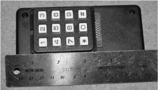
Figure 20-3 Measuring the dimensions of the keypad for mounting.
When choosing a project case for the numerical keypad, consider the width of the main panel circuit board because it has to fit between the edges of the box lid or sides. If you have the SparkFun keypad, there is a very detailed drawing and printable template on their Web site. Since our hand cutting would be the weak link, we just decided to trace out the dimensions as shown in Figure 20-4 and then hand-bombed the rounded edges by drawing them freehand. Hand cutting the rounded rectangle will be okay using a notching tool and a small round file, so perfect accuracy won’t be possible.

Figure 20-4 Marking the dimensions of the keypad for cutting.
Whenever you are faced with the task of cutting a square or rectangular opening in a thin plastic or metal project box, the notching tool shown in Figure 20-5 will make the job easy. This tool basically nibbles a tiny square bit out of the surface each time you close the pliers, so you can notch away along a straight line, creating any size opening with straight edges. The tool is no replacement for a CNC mill, but it does a decent job for prototyping. You will have to drill starter holes at each corner and then work the notching tool along the edge until all four corners have been connected. A fine pitch flat file can be used to clean up the edge later if necessary.
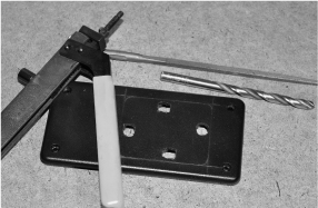
Figure 20-5 The notching tool is a great addition to your hacking toolkit.
Cutting along the edge of the lines, the notching tool takes out one small nibble at a time, eating a straight line out of the plastic enclosure as shown in Figure 20-6. The key to making a smooth cut is to keep the tool aligned along the edge of the line so that no jagged edges are formed. The cutout can be made fairly accurately using this tool, but don’t expect perfection.

Figure 20-6 Cutting the rectangular opening one nibble at a time.
Figure 20-7 shows the results of using the notching tool to cut the opening and then spending some time with a fine pitch file to clean up the edges and create the rounded corners. The opening is not perfect, but once the keypad is inserted, it looks like a factory job. We wouldn’t want to do 10 of these this way, but for this prototype, it did the job.

Figure 20-7 The keypad fits like a glove after cutting the opening.
Once inserted, the keypad circuit board has just enough room between the box lid edges and the edges of the board as shown in Figure 20-8. This is why an enclosure with an inside diameter slightly larger than the edges of the keypad circuit board was necessary. An external mounting of the keypad would not be so critical.

Figure 20-8 The inside edges of the circuit board have just enough clearance.
You will need to solder a wire for each row and column needed on your keypad as shown in Figure 20-9. Having four rows and three columns, our keypad needed seven wires in total. If your keypad has digits you don’t plan to use, it may be possible to leave an entire row or column unconnected, but you will need to look at the datasheet to see how many digits you will lose by leaving a row or column unconnected. If we dropped row four from the panel, we would lose keys “*,” “0,” and “#” according to the matrix mapping shown in Figure 20-2. We didn’t care about the symbol characters, but wanted to use the zero, so we had to connect all of the rows and columns.

Figure 20-9 Soldering the keypad matrix wires to the circuit board.
To scare trespassers away, a very loud, ear-piercing siren will be needed. The high-pitch sound will travel a great distance and make it almost impossible to locate the actual alarm system, making it impossible to disable in a hurry. You have many choices for alarm hardware, with battery voltage being the only consideration. The pocket alarm shown in Figure 20-10 is a perfect choice for this project because it will run from any voltage between 3 and 5 volts (V), and can be switched on using a small relay or even transistor. The pocket alarm is inexpensive (normally retails for under $10), even less than a basic DC-operated piezo buzzer, so consider it for this project.

Figure 20-10 This tiny pocket alarm is amazingly loud for its size.
Inside the pocket alarm (Figure 20-11) you will find a few coin batteries, a small circuit board with an oscillator and inductor, and the piezo transducer that makes the high-pitch siren sound. This thing is so loud that it makes our ears ring, which is quite impressive given its size and the fact that it runs from the low current 4.5-V coin battery source. At 3 or 5 V, the siren worked the same, so conversion to a microcontroller-based project is easy. The pocket alarm operation is simple: you pull a rip cord pin, which closes a switch and turns on the alarm. To convert this alarm for triggering through a relay, remove the rip cord pin and replace the battery pack with the switched output from a relay.

Figure 20-11 Converting the pocket alarm for relay operation.
With the rip cord pin removed, the alarm will now be in the on position permanently. To control it externally, solder a pair of wires to the battery terminals as shown in Figure 20-12, and whenever a voltage between 3 and 5 V is applied, the alarm will begin to shriek. Use a pair of color-coded wires that will make it easy to determine polarity so that you don’t accidentally reverse the power to the alarm circuit.
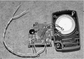
Figure 20-12 Replacing the internal batteries with a pair of wires.
Once you have the wire pair soldered to the battery terminals, apply power to verify that the alarm is working properly. Drill a small hole in the back or side of the alarm casing as shown in Figure 20-13 so that you can connect them to the relay that will be installed in the alarm system circuit.
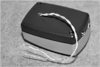
Figure 20-13 The completed externally powered pocket alarm.
This alarm system will work in “self-contained” mode where the sensor is affixed to the alarm box or in “remote mode” where the intruder sensor is installed via wire to another location. In self-contained mode, this alarm system is great for protecting drawers, luggage, and doorways as it is as simple as arming the alarm and placing it in an area that would be triggered by an intrusion. In self-contained mode, the goal of the alarm is to instantly alert you of an intrusion into your space. In remote mode, the alarm can protect several windows or doors at the same time by connecting magnetic or break switches in a series loop back to the alarm unit. Remote mode allows the system to act as a semipermanent building alarm that can be installed in a few minutes.
This project will be completed by testing the alarm in self-contained mode, using a motion-sensitive switch as the alarm trigger. Motion switches come in the form of ball switches, mercury switches, or electronic motion detection IC packages. We just happened to have a few old mercury switches salvaged from some 1980s thermostats, so we will use one of them as a motion switch. Mercury switches are rather rare these days, but the ball bearing switches shown in Figure 20-14 next to the mercury switches are a fairly decent replacement that does not contain toxic liquid metal. Warning: Mercury is poisonous. Any motion switch will work as long as it acts like a real switch, opening or closing when motion is detected.

Figure 20-14 A few different motions switches for self-contained mode.
A passive motion sensor does not require a power supply as it is mechanical in nature, opening or closing a switch in response to motion on its body. You can see in Figure 20-15 that the mercury switch is just a blob of liquid metal that can be at either end of the sealed tube, making contact with a pair of pins at one end. Ball-bearing switches and magnetic switches also work the same way. Since this project puts the microcontroller into deep power saving mode when activated, a passive switch is used so that the alarm can run for a very long time off a battery pack. An electronic switch would slowly drain the power pack, even if it only used a small amount of current, so a passive switch is the best choice here.
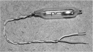
Figure 20-15 Passive switches like this mercury switch are optimal for this project.
The schematic for the portable alarm system shown in Figure 20-16 is fairly straightforward. The rows and columns of the keypad are connected directly to the microcontrollers IO pins so that the program can switch on one column at a time and then scan for row button presses. The input from the alarm sensor (switch) is connected directly to an input pin, and the relay can be turned on by sending voltage from the IO pin connected to the base of the driver transistor. The two light-emitting diodes (LEDs) and piezo buzzer give an audio and visual indication of the various functions of the alarm system.
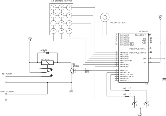
Figure 20-16 The portable alarm system schematic using an ATMega88 microcontroller.
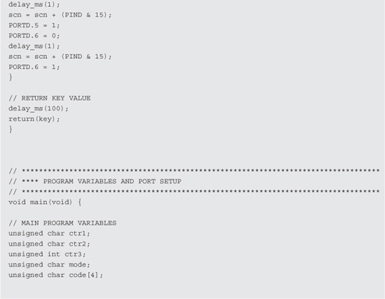
Also note that the wiring shown in the keypad matrix may not match your own keypad, so you will need to determine which pins are rows and which pins are columns, and then make the appropriate changes in the code dealing with the IO pins on PORT-D that connect to the keypad rows and columns. As for VCC, either 5 or 3 V will work fine with the ATMega88, but when using 3 V, you will have to ensure that the relay chosen will close on this low voltage. Most relays rated for 5 V will work just fine on 3 V.
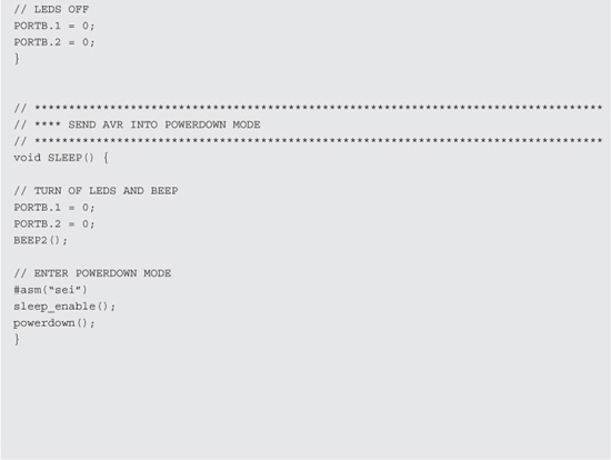
Before committing any permanent circuit board wiring, build the circuit on a solderless breadboard as shown in Figure 20-17 so that you can easily program the microcontroller, make source code changes, and alter the circuit to suit your needs. Some of the things you will want to alter in the source code will include the secret password (found under program initialization), which is currently set to “1234,” as well as the times between activation and triggering. Some of the program code is specific to the ATMega-88, allowing it to be sent into deep power-saving mode once the alarm has been set to armed. Power-saving mode is deactivated by any change on the alarm sensor pin via pin change interruption, allowing this system to run for a very long time once set to armed.
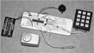
Figure 20-17 Building the portable alarm system on a solderless breadboard.
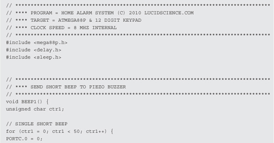


If you intend to use the alarm system for personal protection where you want to be alerted instantly to any intrusion, then change the counter check value under the section “Mode 2: Alarm triggered with 60 second countdown” and in the line “if (ctr3 == 400) mode = 3;” from 400 to some smaller value like 50. You will of course have to experiment with the code to change it to suit your needs, but it is well-commented and very easy to modify or improve.
Without altering the source code, the operation of the portable alarm system is as follows: Once powered on, the LEDs will flash to indicate that everything is working, and then the green LED will stay lit to indicate the system is idle and waiting for the secret code to be entered. Once you enter the secret code of “1234,” the red LED will flash for 60-seconds, giving you time to exit the building in order to set the alarm trigger switch to the armed position. After 60 seconds, the alarm will enter a deep power-saving mode, and both LEDs will be off. Any change on the alarm trigger switch or sensor will wake up the alarm and begin another 60-second countdown. If you do not enter the secret code within 60 seconds, the relay will close, sending power to the loud alarm until the entire system is powered off. If you do enter the secret code within 60 seconds, the system will enter the idle state again. This operation is much like a typical house alarm system.
Once you have verified the operation of the alarm system and made whatever source code changes may be necessary, collect all of your required parts and find a suitable perforated circuit board to hold the six or seven semiconductors, including the microcontroller. As shown in Figure 20-18, most of the inventory will be hardware, and the actual circuit board will only take up as much room as needed for the microcontroller, relay, and a few resistors. When working with microcontrollers, it is always a good idea to use a socket on your circuit board so that you can remove the microcontroller for reprogramming if you don’t intend to add an in-circuit programming header.

Figure 20-18 Getting ready to build the final version on a circuit board.
Perforated board is available with solder pads like the board shown in Figure 20-19, or with unclad holes. Both types will be fine for this project since there are so few components to wire. Parts are placed on the perforated board, and then small wires are soldered on the underside, between the component pins to create traces. Since the microcontroller and relay will take up most of the room, the circuit board does not have to be much larger than both parts. The wiring on the keypad has also been trimmed so that there is just enough slack that the circuit board can be folded around and stuck to the back of the keypad, making for a compact final product.

Figure 20-19 Adding the components to a small perforated circuit board.
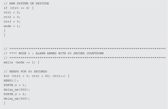
To make the perforated board design easier, start with the VCC and ground connections, using red and black or red and green wires so that there will be no polarity reversal errors. The rest of the connections are easy enough, with the seven IO lines from the keypad taking up most of the wiring. Figure 20-20 shows our completed circuit board, with various colored wires used to make debugging easier.
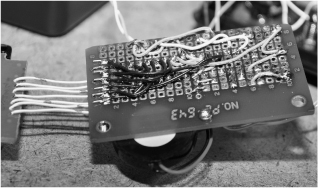
Figure 20-20 Creating circuit board traces using small wires.
Once your circuit board has been completed and tested, some space can be conserved by folding the circuit board to the back of the keypad as shown in Figure 20-21, holding there with a bit of double-sided tape. We also added the piezo buzzer to the board, making the entire system not much larger than the keypad. The 1/8-in jack shown in Figure 20-21 is to allow the external alarm trigger switch to be removed and swapped with various different trigger systems for more versatility.
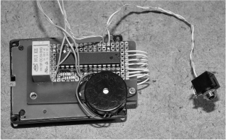
Figure 20-21 Affixing the circuit board to the back of the keypad.
To get the most volume out of the alarm siren, it should be mounted to the outside of the box, or at least in a way that places the speaker portion outside the enclosure. Figure 20-22 shows the alarm siren held to the side of the enclosure with a few tiny screws as well as the 3-V battery pack, which is held to the bottom of the box with a small bit of double sided tape. Keep all wiring long enough so that when you remove the lid (and circuit board), you can get at the underside of the board easily.
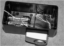
Figure 20-22 Mounting the alarm siren and the battery pack to the enclosure.
Figure 20-23 shows the completed and working system before placing all of the components into the enclosure. Having the wiring long enough to spread out the components like this means that debugging a bad connection will be much easier. There is also plenty of room in the enclosure in case later hardware upgrades are needed.

Figure 20-23 Completing all of the hardware wiring connections.
The master power switch will cut power between the battery pack and the circuit, and it is also the only way to shut off the alarm once it is triggered by an intruder. Figure 20-24 shows the rocker switch we chose to use as the master power switch. The square switch requires the notching tool to be used again to cut an accurate square hole, but since we had a bunch of these switches salvaged from old computer power supplies, it made sense to use one.
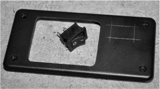
Figure 20-24 Adding the master power switch to the system.
To secure the keypad to the inside of the enclosure lid, we used a bead of hot glue around the edges as shown in Figure 20-25. The keypad also had four small mounting holes, but the hot glue was just as effective in hold the panel securely to the plastic lid. We also ran a bead of glue around the master switch just to ensure it would not come loose from the hole. As a travel alarm, you will want to make your hardware as durable as possible, especially if it will travel in a suitcase. Be warned, though, that airport security might not allow you to bring the device in your carryon or checked luggage—for obvious reasons.
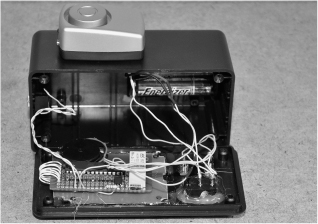
Figure 20-25 Sealing the hardware using a hot glue gun.
In portable mode, the alarm trigger switch is connected to the alarm enclosure so that the entire system is one piece. This allows the alarm to protect such things as luggage, dresser drawers, filing cabinets, doors, and any other object that will move when an intrusion occurs. By installing the mercury or ball switch on a short piece of stiff wire on the connecting jack as shown in Figure 20-26, it is easily aligned in any position, allowing the alarm box to be “set” at any angle and armed. Other types of sensors such as microswitches, magnetic switches, or trip wires could also be used in portable mode, allowing the alarm to be set up to protect just about any area or object from intrusion. In this case, you will also want the alarm activation countdown timer to be set to a very short duration—or none at all—so that the instant the alarm is disturbed, the siren begins to wail.
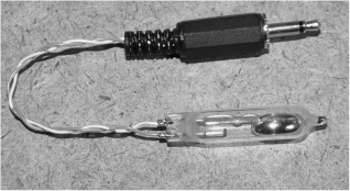
Figure 20-26 Creating the motion trigger switch for portable mode.
With a roll of double-sided tape handy (Figure 20-27), the portable alarm system can easily be installed on doors, drawers, or even inside a vehicle to alert you and scare away potential intruders. The motion switch is shown sitting on the top of the alarm cabinet in Figure 20-27, waiting for any movement of the box to set off the extremely loud siren. By adjusting the angle of the motion sensor on the stiff wire, you can fine tune the alarm sensitivity the way you want it.
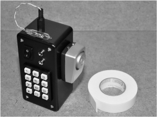
Figure 20-27 Double-sided tape will help install the alarm in portable mode.
Figure 20-28 shows how easy it is to adjust the motion sensor on the end of the wire so that the alarm can be installed at any angle or position. Here it is set to go off if our highly secret electronic prototype drawer is infiltrated by corporate spies! Using the ball switch or mercury switch, it is nearly impossible to open the drawer without setting off the alarm, even if you know it is there.

Figure 20-28 Protecting our top secret prototype storage cabinet from spies.
One of the reasons we made this alarm system was so that we could bring it on travels and protect our rented room or luggage from thieves. It’s not fun when a thief slips into your room at night and “borrows” your laptop, so this simple alarm will scare would-be thieves away before they get to your valuables. Sure, this may not be the most high-tech security system available, but one thing we have learned from the school of hard knocks is that you don’t need the best security system in the world, just one better than your neighbors’! Seriously, thieves normally want an easy target, which means a room without any security system at all. Figure 20-29 shows the alarm system working to protect the interior of an unlocked room by leaning it up against the door in motion-activation mode.

Figure 20-29 A simple way to scare away burglars.
We also used this alarm system to protect several storage buildings on our property that did not have power available. By installing magnetic door and window switches via wires to the alarm system, it was able to act much like a typical home alarm system, allowing time to set or deactivate the alarm using the secret code during entry and exit. In this mode, the alarm unit needs to be inside the building in a place that is out of the way, just in case the intruder is brave enough to hunt around for the alarm unit as it is screeching away. The intruder will likely flee the scene right away, and even if he/she does try to find the alarm box, it will be very difficult as the high pitch of the siren is not at all easy to track. Figure 20-30 shows the alarm mounted in one room while the magnetic door sensor is in another room. Multiple sensors can be chained in parallel this way as long as they are all either “normally open” or all “normally closed” circuit.
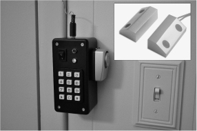
Figure 20-30 A semipermanent installation using a magnetic door switch.
This project leaves plenty of room for improvements and modification, and you can use just about any sensor imaginable to trigger the alarm system. Infrared motions sensors, gas sensors, light sensors, sound sensors and even radiation sensors can be used as long as you power them externally. If you build this project using surface mounted components, it could be made very small and easily concealed inside another object, making it very stealthy. You will never have to be without some kind of security system wi th this simple project!