
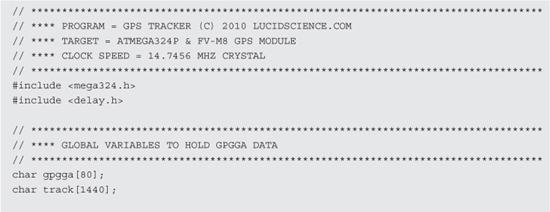
PROJECT 15
GPS Tracking Device
THIS PROJECT COMBINES an 8-bit microcontroller along with a GPS module to create a simple tracking device that can record and play back location data to a mapping program like Google Maps or Google Earth. This project demonstrates the basic method of serial communication between the GPS module and microcontroller, as well as how to decode the data stream being sent from the GPS module. To make this project easy to follow, the source code and hardware are both made to be as minimal as possible, leaving a lot of room to build a much more powerful tracking system.
GPS is short for “Global Positioning System.” As the name implies, it is a globally available positioning and time system that uses a radio fix on multiple orbiting satellites. A GPS receiver will operate wherever there is an unobstructed view (line of sight) to four or more GPS satellites so that it can receive the radio signal from each satellite. The receiver uses the information it receives in the radio signal to determine the distance to each satellite. The position of the receiver is calculated by an algorithm that includes both the information and strength of the radio signal received from each satellite. With this information, exact time, and position data such as latitude, longitude, height from seal level, moving speed, and direction can be computed and displayed to the user.
A GPS module is a self-contained GPS receiver that does all of the difficult signal processing and computation for you. These inexpensive and amazing 1-inch (in) square boxes will lock onto all satellites in range and then start sending out the location and time data in a simple to read string that can be received by a microcontroller using a few input/output (IO) lines. This project will explore the basics of connecting one of these GPS modules to a microcontroller in order to receive the data and record it for later use in a computer mapping program such as Google Earth.
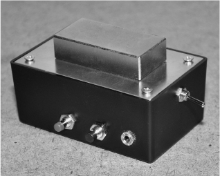
Figure 15-0 This project demonstrates a simple AVR based GPS tracker.
GPS receiver modules have come a long way over the last few years. The tiny 1-in square FV-M8 receiver module shown in Figure 15-1 is from San Jose Navigation, and is ready to use as soon as power is supplied. Once powered up, the GPS module will search for satellites and then send a 1-Hz “heartbeat” pulse down one of the input/output lines to show that it has a valid fix. The module will also send out serial data containing all of the relevant GPS information so that a microcontroller or terminal can decode the data. So, to add GPS capabilities to your project, you really only need three wires: one for power (3.3 volts [V]), one for ground, and one to receive the serial data. All of the difficult work of receiving the RF signal for triangulation is done inside the module for you.
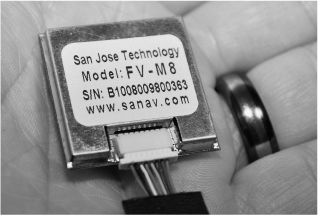
Figure 15-1 The San jose FV-M8 GPS module from SparkFun.
The GPS module came with a small cable and connector set that would be perfect for installation onto a printed circuit board, but not much use for breadboarding work. We decided to convert the cable for breadboard use by cutting it in half so that we could solder a row of header pins to the wires (Figure 15-2). This would essentially give us two cables when done, as the GPS compatible connectors would remain at one end of each half of the cable after cutting.

Figure 15-2 Converting the GPS connector for breadboard use.
According to the FV-M8 datasheet, all of the signal lines were either DC or digital, so there would be no issues with modifying the connector or cable length. The data sheet will show you the pinout of the GPS connector, as well as all of the timing and communications parameters that are needed. If you are planning to use a development board that will accept the connector for your GPS module, then the IO pin configuration is not important at this time, but eventually you will probably want to reduce your project down to just the GPS module and a microcontroller. Figure 15-3 shows the section of the datasheet that indicates the purpose of all eight wires coming out of the GPS module. Out of the eight possible wires, we only needed three of them to get the data into the microcontroller: power (VIN), ground (GND), and transmit (TX1).
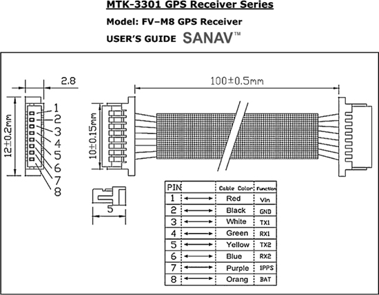
Figure 15-3 The datasheet will detail the IO lines as well as default settings.
The cable that came with the GPS had a male 8-pin connector at each end, so we decided that if we simply cut the cable in half, we could make two new cables: one with breadboard-compatible pins and another that could later be soldered to whatever circuit board we planned to make our GPS project on. The cable shown in Figure 15-4 was cut in half, and then one side was separated so that each wire could be soldered to a breadboard compatible header pin. Since SparkFun also sold these small cables and sockets separately, we could always acquire another one if we decided to use the original socket on a printed circuit board later on.
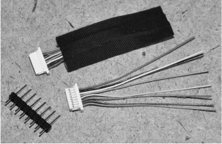
Figure 15-4 Converting the GPS cable to work on a breadboard.
Once the eight colored wires were soldered to the header pins, the GPS cable was now ready to be plugged into any solderless breadboard for rapid prototyping. The colors of each wire were fairly obvious, with red being VCC and black being GND, so it would be difficult to connect the power in reverse. Besides power and ground, the only other wire we planned to use from the possible eight, was the serial transmit line (white wire). We connected all eight wires to the header pins just in case we wanted to experiment with changing the default parameters on the GPS module using the serial receive line. Figure 15-5 shows the completed breadboard compatible GPS module and cable.
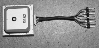
Figure 15-5 The completed breadboard compatible GPS cable.
The goal of this project is the bare minimal simplified system that will record GPS coordinates at a set rate into the microcontroller’s built-in memory so that they can then be played back and viewed on a mapping program like Google Earth. To get the GPS module to communicate with the microcontroller, the hardware serial port (USART) on the AVR ATMega324p is set as a transmitter/receiver for 38,400 baud, which is the default serial transmission speed of the GP module on power up. On the 324p, the serial receive pin is on PORTD.2 as shown in the schematic (Figure 15-6).
To communicate with the computer, the serial transmit line on the 324p (PORTD.1) is fed to an RS232 level converter so that the voltage expected by the PC is correct. The MAX232 from Maxim-IC is an easy to use serial level converter that will take the 3- or 5-V serial output from the microcontroller and boost it up to the correct 12-V level expected by the computer’s serial port. Without the level converter, it is unlikely that the PC would be able to receive the serial data, and even if it did, there would be a lot of errors and bogus data received. As you can see in the Schematic shown in Figure 15-6, the MAX232 level converter only needs three external capacitors in order to function, so it is a very easy to use and inexpensive solution to allow any microcontroller to talk both ways to a PC serial port.

Figure 15-6 Basic GPS tracking system schematic using an ATMega324.
Since the old 9-pin PC serial port is now considered retro, you may want to use the USB port instead. A similar serial level converter and translator integrated circuit (IC) called the FT232 from FTDIChip will do the same work as the MAX232, but for translation between the microcontroller’s serial port and the PC’s USB port. If you search Google for “FT232 to AVR,” you will see that like the MAX232, only a few external capacitors and resistors are needed to allow a microcontroller to talk to the PC using a virtual USB serial port. Choose whichever serial communications method is available on your PC, but remember—without the level translator (MAX232 or FT232), you cannot expect to receive serial data from the microcontroller reliably or even at all.
Besides the GPS module and serial level converter, the schematic only has a few other parts: two push button switches and three optional indicator light-emitting diodes (LEDs). The two buttons trigger record and playback, so that GPS location points can be stored into the microcontroller’s internal SRAM at set intervals. When in playback mode, the GPS information is streamed out to the PC at high speed in the standard NMEA $GPGGA format so that programs like Google Maps or Google Earth can read and display the data. Basically, this project is an ultrasimplified yet functional GPS tracking system that will record location points until it fills whatever memory you have available. The status LEDs show both the record and playback mode status as well as the GPS lock status.
The basic GPS tracking system is shown in Figure 15-7, first built on a solderless breadboard for easy prototyping. If you have not yet read the “GPS Data Receiver” project, that would be a good start as it offers a good intro on working with GPS modules and microcontrollers. As you can see, the AVR324p is only using a few of the 32 available input/output pins, but we needed a microcontroller with a decent amount of internal SRAM in order to store the GPS data, so this meant using a large IO package. Realistically, you will need a much larger storage memory for GPS points than what is available on any microcontroller, but this project is just a simplified demonstration that leaves a huge amount of room for improvement.

Figure 15-7 The GPS tracking system built on a solderless breadboard.
Since both the GPS module and microcontroller will run fine on a 3-V power supply, we chose to use a pair of AA batteries in order to later create a small self contained tracking system that could be stuck to a vehicle using a magnet mounting system. The MAX232 level converter is being underpowered on 3 V, but we have never had any PC communication issues with running them this way. If you are a stickler for specifications, then there is actually a low-power (3 V) version of the MAX232 level converter available, but only in a surface mount package.
Since the FV-M8 module will be sending out serial data at 38400 BPS (its default setting), we needed to choose a microcontroller with a hardware serial USART and then find a clock oscillator that would allow the serial speed to be set with minimal error. When working with lower speed serial communications such as 2400 BPS or 4800 BPS, you can often get away with any clock speed, but for higher data rates such as 38400 BPS, there are “magic” frequencies that will ensure that you end up with an error free communication system. 14.7456 was one of these well known “magic” serial communication clock speeds, so it was easy to source this crystal. The crystal oscillator shown in the breadboard in Figure 15-8 was one of several that we had in the salvaged parts bin, and probably came from an older PC modem card.
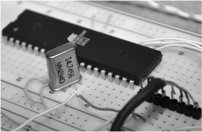
Figure 15-8 For high-speed serial communications, clock speed is important.
Some programming languages such as C, Basic or Arduino have built in serial routines that use both the hardware USART on the microcontroller or simply bit bang the data stream out of an IO port. Keep in mind that these built in routines also suffer from errors if the master clock frequency is not chosen carefully. At 16 MHz, the Arduino was unable to properly receive 38,400 baud the serial stream from the GPS module due to the resulting error in transmission speed. Using CodeVision C, we managed to get somewhat better communications at 20 MHz from the GPS module, but in reality you will probably need to choose a proper clock frequency to satisfy the high-speed serial USART if you want reliable communications from the GPS module or out to the PC through the serial port. These “magic” clock speeds are listed in the microcontroller data sheet and on some of the compilers (such as CodeVision AVR) when starting a new project. Consider this when working with serial data rates over 4800 baud.
Besides a few capacitors and a DC power supply, the MAX232 does not need any other components in order to operate as a serial level translator between your microcontroller and any PC (Figure 15-9). The USB counterpart (FT232) is also a single IC solution for interfacing the 3- or 5-V digital world to the PC through a virtual USB com port. If you only needed to send data to the microcontroller, then the level converter would not be necessary, but since the microcontroller cannot drive the PC serial port with enough voltage, it is needed to send data to the PC serial port.

Figure 15-9 The MAX232 will translate voltage levels for PC serial communication.
If you plan to work with serial communications, then the schematic shown in Figure 15-10 will be very handy to make on a small circuit board or perforated board. We have several boards that include the MAX232, as well as the FT232 so when we need to send or receive data between a microcontroller and PC, it’s just a matter of plugging in the board to the project or breadboard. The schematic shown in Figure 15-10 is a one way system from the microcontroller to the PC, but to use it the other way (or both directions), just connect the input or outputs to the serial connector and MAX232 IC. The FT232 USB serial translator works the same way, allowing two way communications between any low-voltage logic and the PC USB virtual serial port.

Figure 15-10 Using the MAX232 to send data to the PC serial port.
To receive data on a PC serial port, you need to connect only two lines: ground (pin 5) and the serial receive line (pin 2). (See Figure 15-11.) This assumes that you are using a standard 9-pin serial port on your PC. Once these two lines are connected, the serial data stream can be sent to the PC from the level converter.
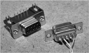
Figure 15-11 Connecting the 9-pin RS232 PC serial port connector.
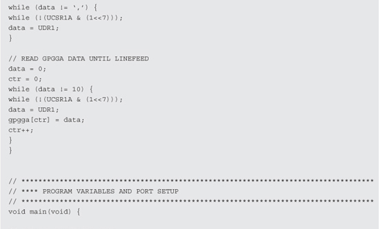
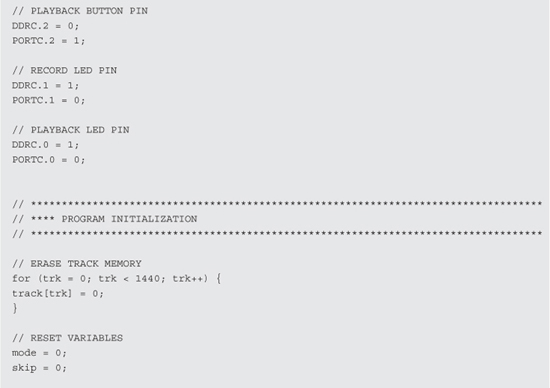
Once you have the circuit built on a breadboard and have the serial or USB connection to your PC ready, compile the simple GPS data logging program to your microcontroller. This program was done in CodeVision and is made for the AVR324p, but it would be very easy to convert it to just about any microcontroller. The real limitation is the amount of data that can be stored in the internal SRAM of the microcontroller, but by expanding the program to use a serial EEPROM or Flash memory, it could easily store hours or days worth of GPS data. For now, just get the basic system working so that you can verify that the microcontroller can decode, store, and then playback GPS data to your PC.
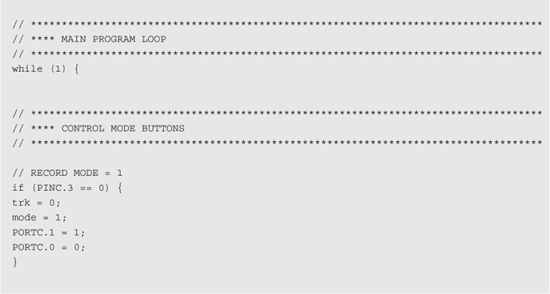
The operation of the microcontroller program is very simple. If you press the record button, the record indicator LED will stay on as data is stored into the internal SRAM. When the record LED is out, you can then press the playback button to stream out the data to the serial port on the PC. The data is formatted so that programs like Google Earth and Google Maps think that a standard GPS unit is connected. Having only a few kilobytes free, the AVR324 can store about 20 full NMEA strings before the SRAM is full. This is certainly not much data, but enough to test your hardware with a quick drive around the block. This GPS tracking test program is based on the source code from the GPS data reviver project, and is explained in much more detail there.


Before taking your breadboard on a test journey, first make sure that your PC can receive the serial data stream by opening a terminal program such as Hyper Terminal, which is built in to Windows. Most compilers and IDEs also include a serial terminal, so connect your USB or 9-pin serial cable and then open the terminal of your choice for receive at the same baud rate that your GPS and microcontroller are set to. As shown in Figure 15-12, the serial communication settings are 38400,8,N,1 (38,400 baud, 8 bits, no parity, and 1 stop bit). “8,N,1” is a common setting from just about every device.
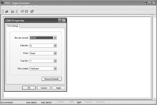
Figure 15-12 Testing the serial communications using a PC terminal program.
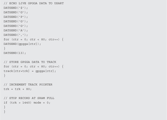
Figure 15-13 shows a screen full of various NMEA strings received directly from the GPS module. This data stream is taken directly from the GPS module by moving the TX pin from the GPS to the RX pin on the MAX232 chip. Basically, this takes the microcontroller temporarily out of the loop just so you can verify that your GPS module is spewing out data. By default, the FV-M8 GPS module was sending multiple NMEA messages at a rate of five per second. NMEA messages start “$GP” and then include a three digit identifier code to indicate what format the message is in. The screen capture in Figure 15-13 shows five different types of NMEA headers and messages streaming in from the GPS module; “$GPGSA,” “$GPGSV,” “$GPRMC,” “$GPVTG,” and “$GPGGA.” We will only be decoding the GPGGA data string in the microcontroller, but the GPS module sends all five by default.

Figure 15-13 Displaying the live data stream from the GPS module on the PC.
Most GPS modules output data in the NMEA (National Marine Electronics Association) format, which is a collection of standardized data formats that contain comma separated values flowing an identifier code. When you are coding your own GPS software, you will definitely need to get familiar with the data format sent by your GPS module and choose one of the many possible strings to decode. A Google search for “NMEA strings” or “NMEA sentence” will yield all of the information you will ever need for every possible NMEA string format.
Once you have determined that your GPS module is sending serial data by viewing it directly on the PC terminal, move the TX pin back to the microcontroller so that the NMEA messages can be read and then decoded by the microcontroller program. The data streaming in to the computer terminal will stop because the microcontroller will not send them until one of the buttons has been pressed.
Press the record button, and the record indicator LED will stay on for a few seconds while it saves 18 GPS coordinates into the internal SRAM memory on the microcontroller. We have set the program to save every 20th $GPGGA data string, and since the GPS unit sends them once per second, the record LED will stay lit for 20 seconds. You can easily adjust the frequency of the recorded strings by changing “if (skip == 20)” to some other value in the record loop. At the same time that data is being recorded, it will also be sent out to the serial level translator and to your computer terminal program. The decoded and rebuilt data will look like the data shown in Figure 15-14, having only the $GPGGA strings displayed. All other characters and strings have been stripped away, so the data is much more readable now.
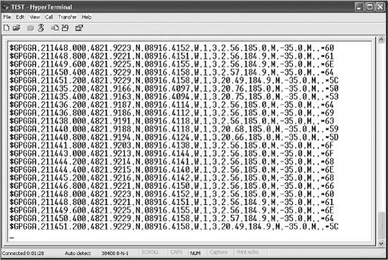
Figure 15-14 Displaying the decoded NMEA string from the microcontroller.
This project assumes that you understand the workings of your GPS module, and if you are using a different GPS module from the FV-M8, you will likely need to adjust either the baud rate or the type of NMEA data being sent. If you can’t set this on the GPS module, then you will need to change these parameters in the microcontroller program to match your GPS modules settings. More information on GPS modules and NMEA string formatting can be seen in the “GPS Data Receiver” project.
Now, let’s use Google Earth or Google Maps to display our current location in real-time. Open Google Earth and then click on the “Tools” menu, followed by “GPS” in order to bring up the window shown in Figure 15-15. In this window, choose “NMEA” as the protocol, and then click on “Automatically follow the path” so that Google Earth will go directly to the location sent by the GPS. Once you press start, the window will disappear, and Google Earth will begin to track the real-time data received on the serial or USB port.
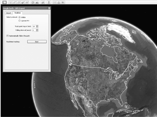
Figure 15-15 Setting Google Earth to display real-time NMEA data from a GPS.
You can either move the GPS module TX line back to the RX pin like before or just press the record or playback button on the breadboard to get data to stream out to the computer. Either way, Google Earth will detect the data stream and then begin to decode whatever NMEA information is being sent. It may take a few seconds to get the globe to move, but once it starts, you will get to fly directly to the exact place on earth that you are currently located (give or take 20 feet [ft]).
Within a few seconds of sending the NEMA strings out to the PC, Google Earth jumps into action and rolls the globe around to zoom into our exact location as shown in Figure 15-16. Having a simple breadboard circuit able to know our whereabouts is both cool and a little creepy at the same time! As for accuracy, a GPS is usually accurate to about 20 ft, but the little location point on the Google Earth image seems to be right over our lab on the house roof exactly where expected. If we click on one of the “Street View” icons near our location, Google Earth zooms down to Street View and we are looking at a summer photo of the house, which is nice considering there is snow on the ground right now.
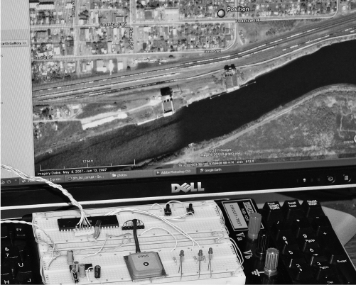
Figure 15-16 Google Earth displays the exact location once the button has been pressed.
Once you have confirmed that the program can successfully receive, store, and then play back the NMEA data from the GPS module, it is time to take your prototype on a test journey. Since this version is limited due to the small amount of internal SRAM in the microcontroller, you will either need to make a short trip or adjust the record frequency to gain more time. Either way, you can only store 18 points in the AVR324 SRAM, but this is only a proof of concept model to expand on later.
We adjusted the record interval time so that we could record points as we drove around a two block radius. It took a few revisions to get the timing down to an even spread of 18 points, but in the end it worked out well. Figure 15-17 shows the breadboarded GPS tracking device ready to go on a trip around the block. As soon as we pulled out of the driveway, we pressed the record button and then made a loop around the next block over and back to the start location. At the end of the trip, the record LED was just turning off, so we knew the data would look like a round trip on the mapping program. Since the project was storing the points in the internal microcontroller’s SRAM, we had to be careful not to disconnect the power as the data would be lost. A large flash memory would be the optimal solution for a long-term GPS data logger.
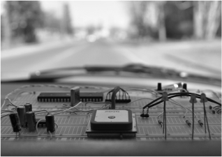
Figure 15-17 Getting set up for a quick trip around the block with the prototype.
This GPS module was very good at acquiring a lock in under a minute, which was actually a little bit faster than the handheld Garmin GPS unit. We did several trips around the neighborhood and had the handheld GPS along recording as well so that we could compare the tracks later on Google Earth (Figure 15-18). Both the GPS module and handheld GPS units showed an accuracy of about the width of the street, only wandering outside the street borders around corners. GPS technology is not accurate enough for indoor navigation, but an outdoor robot would do just fine in a large open area with some onboard obstacle avoidance.
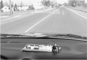
Figure 15-18 En route around the neighborhood, recording GPS points.
Once the trip around the block was completed, the breadboard was carefully moved from the dashboard of the vehicle back to the lab for data downloading. In order to display the trip coordinates on the computer, a mapping program that can import and decode the NMEA strings saved by the program will be used. An easy method of analyzing the data is to simply capture the stream to a text file as it is played back from the microcontroller’s memory. Figure 15-19 shows the GPS data being captured and saved as a text file from the Windows HyperTerminal program. To capture data from a terminal program, chose “Capture Text” and then select a location on your hard drive for the file. Once the file is open, press the playback button to stream the data out to the text file. When you stop the capture, the file will contain the $GPGGA data saved by the microcontroller.
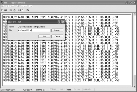
Figure 15-19 Capturing the GPS data for importing into a mapping program.
Since the Google mapping programs could not read the raw NMEA text file saved from the terminal program, it needed to be converted into a format the Google Earth or Google Maps could understand and open (Figure 15-20). Searching Google for “NMEA to KML” yielded several GPS data format converters including one that worked directly online at http://www.h-schmidt.net/NMEA/. We clicked the box to open the file on the local hard drive after saving it from the Windows terminal program. There were a few other options available during conversion, but we just left them all at the default settings.
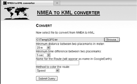
Figure 15-20 Converting the text file NMEA data into compatible KML data.
The online converter read practically any text file that contained valid NMEA strings and then converted them to a format (KML) that works with Google Maps or Google Earth. Having both programs installed gave the option to launch the application directly as shown in Figure 15-21. Hopefully, newer versions of Google Earth will be able to read NMEA text files directly, but for now the many online converters work just fine.

Figure 15-21 Once conversion was complete, the option to save or open appeared.
Once Google Earth opened, the KML file was read and the route was displayed as shown in Figure 15-22, with 16 points making up our entire journey. Comparing this to the data directly downloaded from the handheld GPS that was also along for the ride proved that this prototype was just as accurate as the commercially available GPS unit. For a future experiment, we will jam the works into a small black box, remove the indicator LEDs and include a strong magnet so the tracker can be stuck to a vehicle in some unnoticeable place. If the prototype passes this random “stick and run” test, then our next version will include a much larger memory to store GPS data and possibly some more advanced NEMA string decoding and formatting.
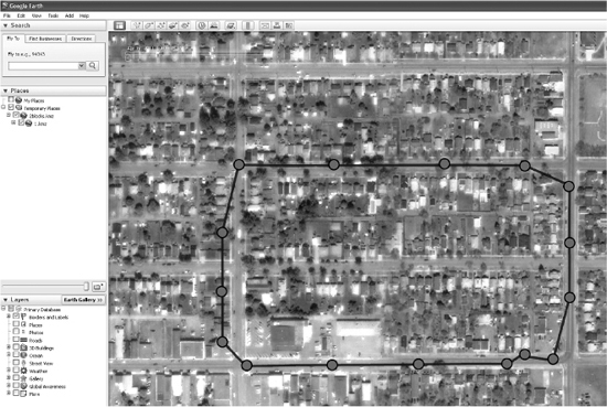
Figure 15-22 My prototype journey is now displayed as a path in Google Earth.
Although a much smaller and cleaner prototype could be made using an actual circuit board and surface-mounted components, we just wanted a quick and easy-to-make boxed version of the GPS tracker for real-world testing. There wasn’t much to this project besides the GPS module, a 40-pin AVR324 DIP, the MAX232 serial converter and a few capacitors so a small piece of perforated board was chosen to make the circuit board. The indicator LEDs were left out this time since they would be visible in the dark and use power for nothing during a long trip. The small black plastic box shown in Figure 15-23 has just enough room inside for the battery pack, the GPS module, and the small circuit board. Because the GPS has a built-in antenna, it cannot be installed in a steel or aluminum case as that would block the RF signal from the satellites. The black plastic box seemed to have no effect on the operation of the GPS as long as the antenna was against the plastic, not the other components.
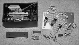
Figure 15-23 Using basic prototyping components for rapid development.
There really wasn’t much wiring to do under the small perforated circuit board since the circuit was very simple. Solder the components to the underside of the board using small wires as traces, leaving room between the pins so they can be bent at 90 degree angles to secure the components to the board. It is also a good idea to use a socket for any microcontroller that you may want to remove for reprogramming (if not using ISP programming), or for a future project. As for the 9-pin serial port, it was too large for the plastic box, so we changed it to a 1/8-in mono jack (shown next to the switch in Figure 15-24). Since only two wires are used for the serial port, any jack would work.
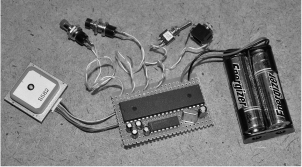
Figure 15-24 Creating the black box prototype circuit on a bit of perforated board.
There was just enough room in the plastic box for the two switches and serial jack after installing the circuit board. This project could certainly be made much smaller with a little work, but it is still half the size of the pocket GPS, so it can be easily hidden under a car or in the box of a truck (Figure 15-25).
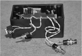
Figure 15-25 Fitting the circuit board and components into the small black box.
The completed GPS tracker prototype is shown in Figure 15-26 after fitting all of the components and hardware in the plastic box. The box has an aluminum lid, but that will be fine since the antenna on the GPS is pressed against the empty side of the box for optimal reception. It will be important to keep the plain side of the box facing outwards when sticking the unit to a vehicle so that the antenna is not blocked by any metal objects. The stealth installation of this tracking unit is very simple: turn on, wait 1 minute, affix to a vehicle on the outside or inside, press the red button. To get the data into Google Earth, just plug in the serial port and press the black button. All that is lacking in this proof of concept model is an external memory with much more room to store GPS coordinates.
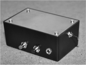
Figure 15-26 The completed GPS tracker prototype ready for action.
Since the small plastic box did not have room for the DB9 serial connector, we just used a 1/8-in mono headphone jack inside the box. The adapter cable shown in Figure 15-27 has pin 2 of the DB9 serial connector going to the tip of the 1/8 connector and pin 5 of the DB9 going to the ground pin on the 1/8 connector. For two-way communications between the PC and GPS module, a 1/8 stereo headphone connector could be used. We did not intend to change the default settings on the GPS module, so the two wire cable was fine.
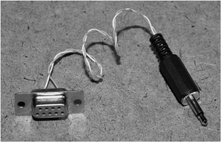
Figure 15-27 To retrieve the data, a 1/8 jack to 9-pin serial port cable is used.
To create a very secure mounting system, we fastened a 2-in long NIB (Neodymium) magnet (Figure 15-28) to the top of the plastic box using double-sided tape. This magnet was actually much too strong for this application, but we didn’t want to lose the GPS on the road. When stuck to a metal body, the magnet holds on with such force that we need to pry it up with a plastic screwdriver as it would tear the lid right off the box if we tried to pull it free. A magnet of half the size would be just fine, but at least we know the GPS tracker unit wouldn’t fall into enemy hands (or a storm sewer).
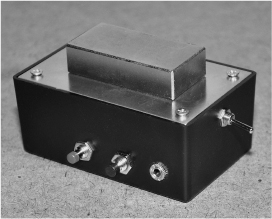
Figure 15-28 A ridiculously strong NIB magnet will hold the GPS to a steel object.
Installing the stealth GPS tracker is as easy as sticking it to any metal surface, but the antenna needs to have some room to receive the faint GPS signals. We found the unit to work well in most installations, including under a vehicle, but the license plate compartment was optimal if it included a small hiding place like the Chevy S10 shown in Figure 15-29. Having the super-strong NIB magnet meant that the GPS tracker could be mounted to the fiberglass parts of a vehicle as long as there was a metal object under the nonmetallic surface.
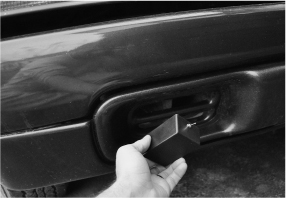
Figure 15-29 Finding the perfect hiding place that would give the antenna a clear view.
Besides much more storage memory, another improvement we will make in the next version is to include the GPS Fix status LED once again so that the system can be started up before placement, saving time and guaranteeing that the unit will begin recording live coordinates as soon as the record button is pressed. Having the Fix LED blink until the recording starts would be best, so that there are no flashing lights on the box. Having a blinking red light would be an obvious giveaway at night, not to mention that the device would look like a small bomb! We are all for pranking our friends, but that would be too much!
The stealth GPS logger prototype performed as well as the breadboarded version and as well as the handheld GPS unit. Only once did the GPS lose the signal, but this was because the antenna was almost fully blocked by some metal objects in one of our test runs. To gain a bit more memory on this simplified prototype, we changed the AVR324p (4K internal SRAM) to an AVR1284p (16K internal SRAM) so that we could record four times as many NMEA strings, allowing about 20 minutes of decent resolution recording. This is still far from being much use in the real world, but did allow a much longer path to be shown on Google Earth (Figure 15-30).
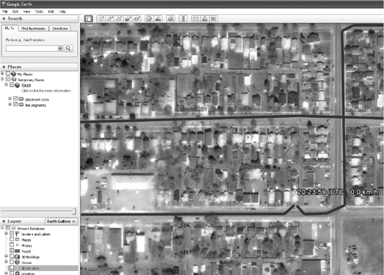
Figure 15-30 The stealth GPS logger prototype can track you around the globe.
The stealthy GPS tracker project was a great success. The simple microcontroller program can be much expanded on to offer greater control over recording frequency and operation. With the addition of an external EEPROM memory or Flash memory, the GPS tracker could be made to store hours or even days worth of information. By adding two-way communications between the microcontroller and PC, a complete terminal-based menuing system could easily be made that would allow the GPS tracker to be configured on the PC, adding features such as scheduling, motion detection, light detection, direction, and speed logging, and many other features that would only take minimal extra hardware. Using surface mount components and a lithium battery pack, the GPS tracker could be made as small as a matchbox, yet run for days using some power-saving microcontroller features. There is no limit to what can be done with this project, so warm up that soldering iron and put your ideas in motion