
PROJECT 18
Remote Control Hijacker
THIS FUN PROJECT lets you take control away from the person holding the remote control by intercepting the invisible signals as they travel through the air so you can play them back to the TV or video machine. You can also “train” your remote hijacker by recording certain button presses directly from the remote so that you can play them back later on, taking total control over the target appliance. Because this project records the remote control pulse stream directly, it will work on any infrared-based remote control, able to learn a few button presses.
![]() IRMOD: rc5 infrared remote control decoder module
IRMOD: rc5 infrared remote control decoder module
![]() IC1: ATMEL ATMEGA88P or comparable microcontroller
IC1: ATMEL ATMEGA88P or comparable microcontroller
![]() Q1: 2N3904 or 2N2222A NPN transistor
Q1: 2N3904 or 2N2222A NPN transistor
![]() LED 1: 940-nm infrared LED
LED 1: 940-nm infrared LED
![]() LED 2: Red or green visible LED
LED 2: Red or green visible LED
![]() S1, S2, S3: Normally open pushbutton switches
S1, S2, S3: Normally open pushbutton switches
![]() Resistors: R1 = 100 Ω, R2 = 10 K, R3 = 1 K
Resistors: R1 = 100 Ω, R2 = 10 K, R3 = 1 K
![]() Battery: 3-V AA or AAA pack
Battery: 3-V AA or AAA pack
This project uses a very simple microcontroller program that just times the pulses coming into the infrared decoder and then stores them in the internal SRAM for later playback. The source code is made as simple as possible, allowing for plenty of room for modifications and alterations to suit your evil genius agenda. Because no interrupts are used, the C program could be ported to just about any microcontroller, and will work on all of the Atmel microcontrollers as is. Larger internal memory allows more button presses to be stored, with the ATMega88 (1K SRAM) allowing about three button presses to be recorded and played back.
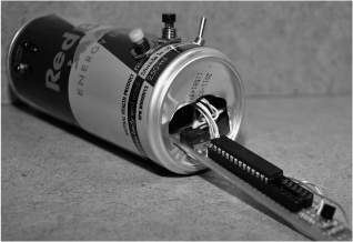
Figure 18-0 This hidden device can intercept remote control signals and play them back!
Almost every electronic appliance that includes an infrared remote control will use a standard method of communication over the invisible beam called the “RC5 Protocol” (see Figure 18-1). This simple protocol works by sending a series of 1.5 to 2.5 millisecond (ms) long pulses that are modulated by a carrier frequency of 36 to 45 kilohertz (KHz). The pulses make up a frame of data, which is usually 12-bits long, encoded using a system of inversion called Manchester Encoding. Of course, we won’t have to dig all that deep into any of this stuff because this project just records the length of pulses and stores them as byte values into the microcontroller’s internal memory for later playback.
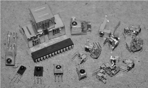
Figure 18-1 The remote control signals are first decoded by the RC5 module.
Of course, you could actually decode the data and store a lot more, but this would require some crafty programming to measure the exact pulse rate and then understand the stream that it is seeing at the input. We just wanted a quick and dirty hack that would allow us to prank the remote control user, so we opted to just measure the time between pulses and store that value. This allows any remote to be recorded and played back as the program does not care what the exact frequency or command being sent really is.
To deal with the very fast 40-KHz modulation, a readymade solution is used that will strip out the modulation and leave only the millisecond pulse train. These remote-control decoder modules are very common as they are used in most of the appliances that we are going to hijack. These tiny 3-pin blocks have a power, ground, and output, and do nothing more than look for RC5 pulses in order to strip them of their modulation. We have collected many of these remote-control modules from various dead appliances and electronics suppliers, and all of them do basically the same thing. Some of them are contained in a metal can, while others look like transistors with a bubble on one side to input the infrared light. All that matters is that you can figure out which pins are power, ground, and output on the device.
In our version of the remote control hijacker, we used the Sharp GP1UM26X decoder module, as we had a few of them that were salvaged from old DVD players and VCRs (see Figure 18-2). If you are going to salvage your decoder module, make sure to take a look on the board before unsoldering so that you can identify the power and ground connections as most OEM modules will have no markings. The ground wire will be easy to locate, but you may have to do a bit of tracing to identify the signal pin. If you have to take a wild guess, then just connect the unit to a 3-volt (V) coin cell with a piezo buzzer and try random combinations until you hear a blip-blip-blip on the buzzer when you aim a remote control at the device and press a button. A coin cell has very low amperage, so it will not kill the module if you hook it up completely reversed while brute force hacking to find the pinout.
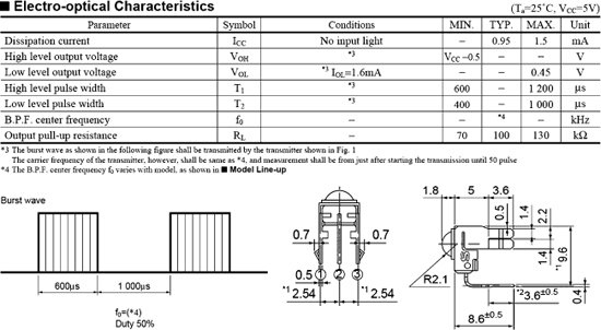
Figure 18-2 The datasheet for a typical RC5 remote-control decoder module.
As for the playback portion of this project, it will utilize the same exact system that is found in the remote control, using an infrared light-emitting diode (LED) to send out the modulated pulse stream (Figure 18-3). You can use practically any type or number of infrared LEDs, as the decoder module is highly sensitive to the modulated pulse stream. In our testing, it was even found that visible LEDs would work! You only need a single infrared LED unless you plan to wreak havoc on the entire neighborhood or the TVs in a large area, but we will leave that modification up to you. A single infrared LED will have more than enough reach to control any TV or video machine in a living room, and since stealth is the goal, size matters.

Figure 18-3 The pulses are sent to the appliance using an infrared LED.
Infrared light has a longer wavelength than any of the colors on the visible spectrum, crossing into invisibility around 800 nanometers (nm), and continuing well beyond 1000 nm (Figure 18-4). Most remote controls use 940-nm infrared LEDs, which is why those types are most common and inexpensive. Of course, you could use any infrared LED, even the 800 to 880 nm types often used for night vision illuminations as well. Either way, your buddy (victim) will not see the invisible light so you can hijack the TV or video player in complete darkness without compromising your funny prank.
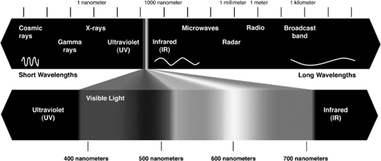
Figure 18-4 The light spectrum, showing the invisible infrared region.
If you like to mull over datasheets, then the important factors of any infrared LED are the center wavelength and the forward continuous current, as this will determine what kind of light and how much light you can expect (Figure 18-5). Of course, for this project, an infrared LED will work, so ratings are not important as the current is low enough due to the supply as well as the short pulses. If you really wanted to get long range from this project, then look at the datasheet for the value of pulsed current rating, which is a much higher value than continuous current, allowing the LED to be pushed into extremely bright pulsed-mode operation.

Figure 18-5 An infrared LED datasheet, showing the optimal wavelength.
Having a very basic schematic and using a microcontroller programmed in C allows the use of just about any microcontroller with a bit of internal SRAM and a few input/output (IO) lines (Figure 18-6). Only five IO lines are needed for the basic version: a digital input for the RC5 decoder, an output for the infrared LED, an output for the visible indicator LED, and two pushbutton inputs. The output to the infrared LED is amplified though an NPN transistor to offer a bit more range, but it will also work if you just push the LED directly with the output pin of the microcontroller through a 500-ohm to 1-K resistor. The timing has been calculated using an 8-MHz clock source so that the ATMega88 that we are using can run from its internal oscillator, further reducing the parts count. The push button switches put the microcontroller into record or playback mode, allowing the interception of a few button presses that are stored in the internal SRAM for later playback. The visible LED flashes to show that the system is receiving pulses when in record mode, but it can also be omitted if you want a smaller and stealthier project.
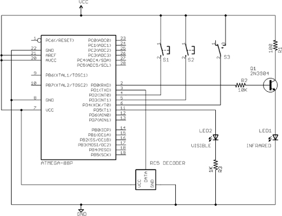
Figure 18-6 The Remote Control Hijacker Schematic.
The source code is written in CodeVision C for the AVR, and is simple enough to be easily ported to just about any microcontroller with an internal memory to store the incoming signals. One kilobyte (K) of memory will store approximately 3 button presses, and a 4 K of memory will store about 16 button presses. Open the source code in your favorite IDE and we will go through it one section at a time.


Under “program variables,” a large 8-bit array is created that will store all of the pulse duration times into the internal memory. The line “unsigned char RC5[750];” sets the largest possible array for the microcontroller, which is based on the amount of internal SRAM, the compiler needs, and the stack. In our case, we have 750 bytes available in the 1024 bytes of the ATMega88 available. You will have to mess around with this number if you are using a different microcontroller, making use of all of the free internal memory space.
The “record function” is called when the record button is pressed, and it takes care of measuring the time between received pulses from the infrared decoder module. On entering the routine, the status LED is turned on to alert the user that the record function is armed. The entire array is then erased. To avoid false recording, the routine first waits for a start pulse from the remote control, sitting in a loop until one is received. Remember that the pulse stream from the decoder module is stripped of all 40-KHz modulation, leaving only the inverted pulses, so this is what will be recorded as a timed value into the storage array.
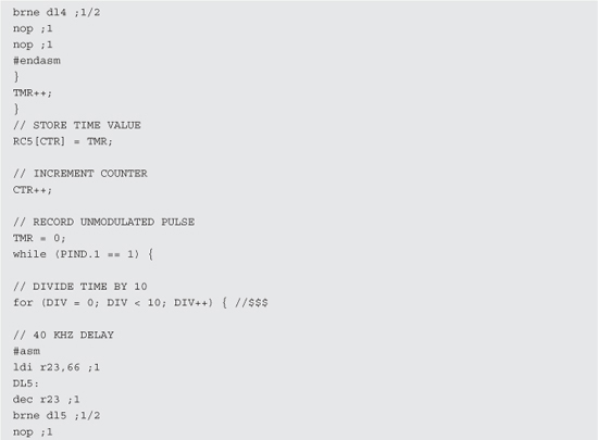
Once a pulse stream begins, the recording routine then resets a counter and stays in a time-controlled loop, incrementing the counter until the pulse changes polarity. The resulting time is the length of the first negative-going pulse (modulated pulse), which is then stored into the array. The following timed loop does much the same, but is now recording what will be the duration of the high pulse (none-modulated pulse). An inline assembly routine is used to mimic the exact timing of the 40-KHz cycle since this will be needed for the playback mode later on.
This recording of low- and high-pulse times continues until the entire array is full, flashing the status LED so that the user can see that valid pulses are being received and stored into the array. To avoid wrapping the memory, the record routine does not exit until the user has let go of the record button. The control is the returned to the main loop, which just sits around waiting for buttons to be pressed.
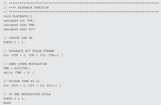
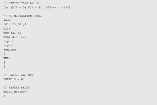
The “playback function” is much like the record function except that instead of recording pulse times to the array, it reads them in series and sends back the missing 40-KHz modulation during the low pulses, recreating the signal that was originally coming into the remote control decoder module. The status LED is turned on during playback to show the user that the unit is transmitting, and continues to read the array contents and send the signal until the end of the array. To create a stable 40-KHz modulation cycle, an inline assembly routine is used again during the low-pulse part of the routine. At the end of the playback routine, the status LED is turned back off, and the control returns to the main loop to wait for another button press.
“IO port setup” is easily adjusted to suit your microcontroller or board layout, and the pull-up resistors are enabled for the switches so they are active low. In the “main program loop,” the routine just sits in a tight loop waiting for either the record or playback button to be pressed so it can call the corresponding routine.
This source code was made as minimal and as easy to understand as possible, so there is plenty of room for improvement and modification. Much better use of the array could be made by first timing the actual start bits so that pulses could be stored as single bits (0:off 1:on) instead of time values. This would allow many more button presses to be recorded into the memory, even on small microcontrollers. This type of efficient pulse decoder would either have to take advantage of interrupts or be done in assembly to achieve maximum accuracy. We wanted this to be a simple project, so we will leave you to make the improvements!
It’s always a good idea to first build your projects on a solderless breadboard so that modifications or debugging is easy (Figure 18-7). This project lends itself well to further improvement, since only a small portion of the program memory and IO space is used. You will also want to test the range, and consider increasing the pulse current to the LED for longer range or simply removing the driver transistor altogether for one room operation. Also shown in the breadboard is the 7805 regulator to allow operation from a 9-V battery, although we used one that was much too large only because that’s what we found in our junk bin. You could probably run the system from 3 V as well if your microcontroller supports it, allowing the use of a tiny 3-V button cell for a highly reduced footprint.
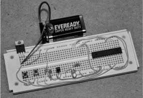
Figure 18-7 The remote control hijacker on a breadboard.
Notice that the infrared input module and output LED are facing the same direction (Figure 18-8). This is done so that you always know which side of your project should face the TV when trying to be sneaky. Since the infrared module is extremely sensitive to the RC pulses, it does not need to actually face the remote control during recording. Infrared pulses reflected from walls and other objects will be strong enough to allow the record circuit to function, but the infrared output needs to be at least pointing in the general direction of the appliance to be hijacked. When you are testing the breadboard circuit, notice how sensitive the infrared input module is, even working with your finger covering the input.

Figure 18-8 The infrared input module and output LED.
Once you have your project on the breadboard with the program running in the microcontroller, place the infrared section close to the TV so that the output from the infrared LED is fed almost directly into the sensor on the TV or appliance. The infrared (IR) input is often hidden behind a dark-black round or square lens near the base of the unit. With the TV on, press the record button on the hijacker and then use the remote control to operate some obvious function like volume or power. As soon as the TV begins to respond, the visible LED on the hijacker should start to flicker, showing you that pulses are being recognized, recoded, and stored into the internal memory.
The indicator LED will stay solid as soon as the record button is pressed, but will flash as pulses are received to show you that it is working. Once the SRAM inside the microcontroller is filled, the LED will stop flashing, indicating that recording is now completed. If the LED fails to flash, then either the wiring is wrong, or your IR module is not sending out pulses properly (see Figure 18-9). You can either probe the output pin with an oscilloscope to verify pulses are being sent, or just drop a piezo buzzer on the output to listen for the blip-blip-blip sound from the output of the sensor.
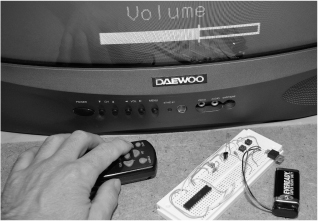
Figure 18-9 Initial testing of the prototype project (record).
Once you have recorded a button press, aim the infrared LED toward your TV and then press the playback button (Figure 18-10). The visible LED will light for a moment as the RC5 pulse stream is sent back to the TV, which will respond to the signal just as it did when you used the actual remote control. If your TV fails to respond, check the output at the infrared LED using a scope or with a piezo buzzer to verify that pulses are being sent. If you hear pulses but the TV fails to respond, compare the time base or sound of the pulses coming in to those coming out to ensure that it is not a clocking or timing problem. If you are modifying this code to work at another frequency, then you will have to alter the timing in the recording loop.
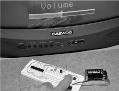
Figure 18-10 Initial testing of the prototype project (playback).
If you keep holding down the playback button, the pulses will continue to loop, which is good when hijacking commands like volume, as you can keep cranking up or lowering the volume by simply holding down the playback button. When you want to drive your remote-control-wielding pals crazy, adjusting the volume is a good method as they will never be able to regain control with you secretly working the remote hijacker. The on and off command is also a good one to prerecord ahead of time as it can be used to turn on or shut off the TV at any time, just like that fun “TV-B-Gone” device.
Once you have verified the operation of the solderless breadboard prototype, it will need to move to a more permanent home on a circuit board or perforated board (Figure 18-11). There are many options to create a stealthy installation, ranging from small and unnoticeable to hidden in plain sight. If you are good with a soldering iron, you could try a surface-mount circuit board using a small pin microcontroller package and then power the unit from a coin battery, making a final product no larger than a pop lid. We opted for the hidden-in-plain sight version using a pop can, as there is nothing suspicions about holding a can while you are sitting there in front of the TV.
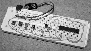
Figure 18-11 Completed prototype ready for a permanent installation.
The easiest method to take a small component count project off the solderless breadboard is with a bit of perforated board (Figure 18-12). The most basic perf board is just a wafer with holes, but there are also protoboards available with copper pads and even interconnected strips just like the breadboard. Having only nine parts makes it easy to use any method of installation, so we opted for a bit of perfboard. Also shown is a pair of smaller sockets connected together to make one large enough for the 28-pin AVR. We did not want to wait around for days to order a new socket, and we always mount microcontrollers in sockets in case we need to remove them for reprogramming or use in another project later on.
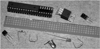
Figure 18-12 Perforated board is good for small component count projects.
Depending upon your installation, the perfboard could be square or long to allow for mounting into an item such as a marker case along with a few coin batteries. We decided to make the board only as wide as the AVR socket and then as long as needed to install the other few components. If we had had a small regulator, the board would be about half an inch shorter, but we usually work with what we can salvage at the time (Figure 18-13).
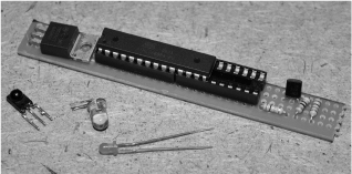
Figure 18-13 Laying out the parts to create the smallest board.
If your components are new, then the leads will be long enough so that you can simply bend them around on the underside of the perf board to create your traces (Figure 18-14). We also bent the four corner socket pins so that it would be held securely to the perf board. If you consider your component layout ahead of time, you will be able to create the connections with minimal wiring, using the leads as traces.

Figure 18-14 The pins are bent to form traces and hold the components.
Since ground and power connections will make up the bulk of the wiring, they are all done first using color-coded wires (red for VCC and green for ground). If there are any mistakes, they will likely be made in these wiring paths, so it makes sense to do them first so that the wiring can be rechecked before applying power (Figure 18-15). Don’t forget to tie down the microcontroller reset pin as well or your system may behave erratically.
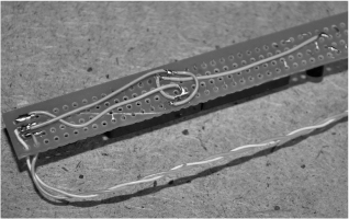
Figure 18-15 Starting the wiring with ground and power connections.
There are quite a few connections that need to be made off of the main circuit such as the infrared module, infrared LED, two switches, visible LED, and battery, so there will be a mess of wires coming from the small board (Figure 18-16). If you already know what kind of enclosure you are going to use, then many of the external parts could be mounted right on the perf board, but we wanted flexibility in our final enclosure so we opted to place all of the parts at the end of the wiring.
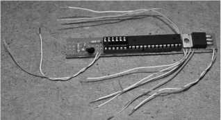
Figure 18-16 The completed perfboard is a mess of wiring.
We added 10-inch (in) long wiring to all of the external components and switches so that we could first mount them in our enclosure (pop can) and then complete the wiring to the circuit board while working outside of the enclosure (Figure 18-17). It always helps to use some kind of color coordination so you know which pin is ground, VCC, or output for each external component.
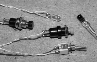
Figure 18-17 Wiring all of the external components and switches.
What is less suspicions than sitting by the TV with a can of pop? We figured that the installation would be perfect as there is plenty of room for the board and battery and all of the switches could be operated away from our victims by holding the can strategically to conceal its true nature. Also, since the infrared signals reflect off of walls, the sensor and infrared LED could also be hidden from those in the room by aiming it away from view. Using a pair of scissors, we popped the necessary holes and then carefully turned the blade until they were the correct size for each external component (see Figure 18-18).

Figure 18-18 Punching holes in the pop can for the external components.
The underside of the can is also cut open to allow the insertion of the battery and circuit board after the switches and infrared components have been installed (Figure 18-19). To feed the switches into the holes, they are guided in place by holding onto the wires.

Figure 18-19 Making an opening for the battery and circuit board.
Once we had the switches installed, we found the best placement for the infrared components so that when we were holding the can with the switches hidden from the person next to us, the infrared components would have a clear line of sight to the front of the room where the TV was located (Figure 18-20).

Figure 18-20 Installation of the infrared components.
The external components are now wired to the circuit board after being stalled into the can (Figure 18-21). It is much easier to test and trouble-shoot the installation with the circuit board hanging out of the can, which is why the wires to the external components were made longer than necessary. This also makes future updates to the microcontroller firmware easier as well.
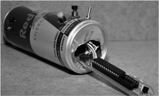
Figure 18-21 Installing the circuit board after the wiring is completed.
To ensure that there are no short circuits, all of the components are held inside of the can using a bit of double-sided tape (Figure 18-22). The tape keeps parts from bouncing around, yet allows the battery to be pulled free if it ever needs to be replaced. The novelty of your evil prank will probably wear out long before the new 9-V alkaline ever will.
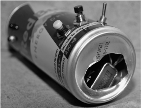
Figure 18-22 Securing all of the internals into the can.
The completed remote control hijacker is now ready to use, and with this stealthy hidden installation, it can be used in plain sight without detection (Figure 18-23). Of course, if your buddies are used to your evil prankster ways, then you might be found out sooner or later, but no doubt you will have some good fun before anyone suspects that your refreshment is stealing the invisible signals from the remote control right out of the air! If you really want to make it look good, open a real can in front of your unsuspecting victim and then do a switch when they are not looking so that any suspicion will not be towards the can you are now holding.

Figure 18-23 The completed remote control hijacker.
Give your new toy a few test runs so you can get used to using the controls in a nonsuspect manner before unleashing your chaos onto the world (Figure 18-24). It may even work best if you get a hold of the remote beforehand and record the power button or mute button so you can enter the room already drinking your favorite refreshment and then just start hijacking the TV without suspicion. Once your victim begins to fiddle with the remote in frustration, you can then intercept new commands just to mess with them even more soon after!

Figure 18-24 The controls are conveniently mounted for hidden operation.
You might have noticed that in our schematic there is an extra IO pin connected to a switch that is not used in the source code. Our intent was to add a timer mode that would just count down for a minute or two and then issue the last recorded command. This way you could be out of the room and just listen to the cursing from a distance, taking away all suspicion from you or your evil contraption! (See Figure 18-25.) Another idea for modification is to just send random pulses on a button press to effectively jam the remote control so that the user can’t do anything at all after you mess with the TV or VCR. Again, there is plenty of room for modification of the remote control hijacker, so feel free to let your evil mind wander and send us a few photos of your completed work for our gallery!

Figure 18-25 Playing back the mute command to the TV after a successful intercept.